bamar EJF series User manual

EJF 3
Via F.lli Lumière 45
47122 Forlì (FC), Italia
Phone: +39 0543 463311
Fax: +39 0543 783319
Email: info@bamar.it
Website: www.bamar.it
Istruzioni di montaggio
Instruction manual
Avvolgifiocco elettrico EJF
Electric foresail furling system EJF

INDICE GENERALE
GENERAL INDEX I
A GENERAL INFORMATION...............................4
Introduction .......................................................4
A-1 Symbols to be found in the manual...................5
A-2 After-sales service.............................................5
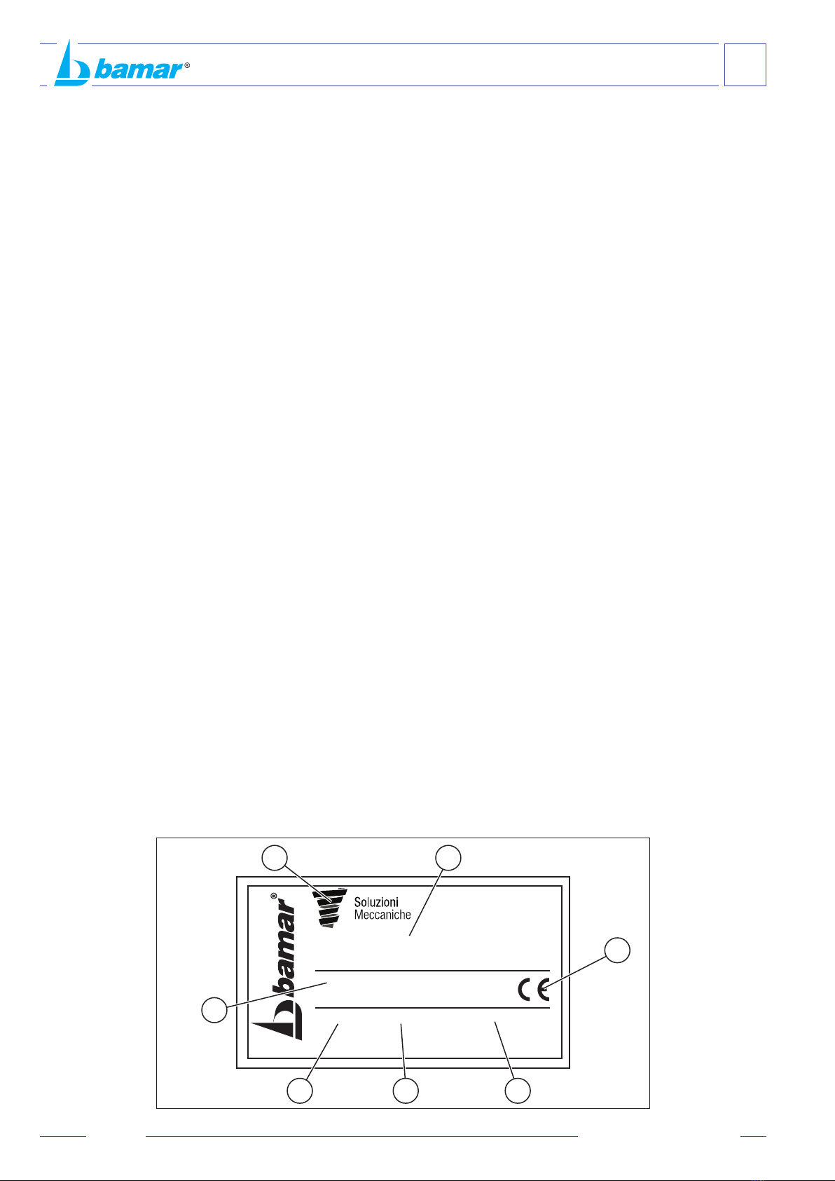
A-3 Identification data ..............................................6
A-3.1 Model and type..................................................6
A-3.2 Manufacturer .....................................................6
A-3.3 Identification plate .............................................6
A-4 Packaging and content......................................7
A-5 Receipt of goods ...............................................7
A-6 Basic tools.........................................................8
A-7 Rules to be applied ...........................................8
A-8 Description of the equipment ............................8
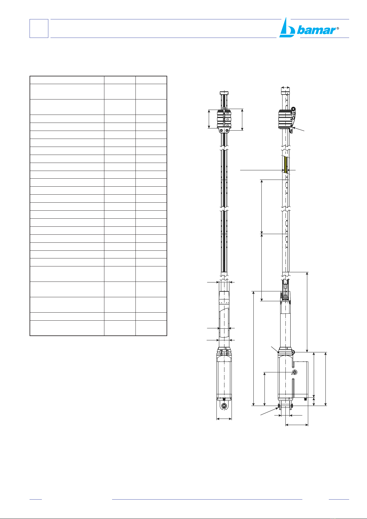
A-9 Technical data ...................................................9
A-9.1 EJF 3 - 3C .........................................................9
A-10 Proper use....................................................... 11
A-11 Wrong use....................................................... 11
B SAFETY ..........................................................12
B-1 General indications .........................................12
C INSTALLATION ..............................................13
C-1 Preliminary operations ....................................13
C-1.1 Stay upper terminal .........................................13
C-1.2 Stay lower terminal..........................................13
C-1.3 Wire stay accessories (optional) .....................14
C-1.4 Chain plate ......................................................14
C- 1.4.1
Deck chain-plate alignment .............................15
C-1.4.2How to rotate the furler's fork ..........................15
C-1.5 Electric connection ..........................................15
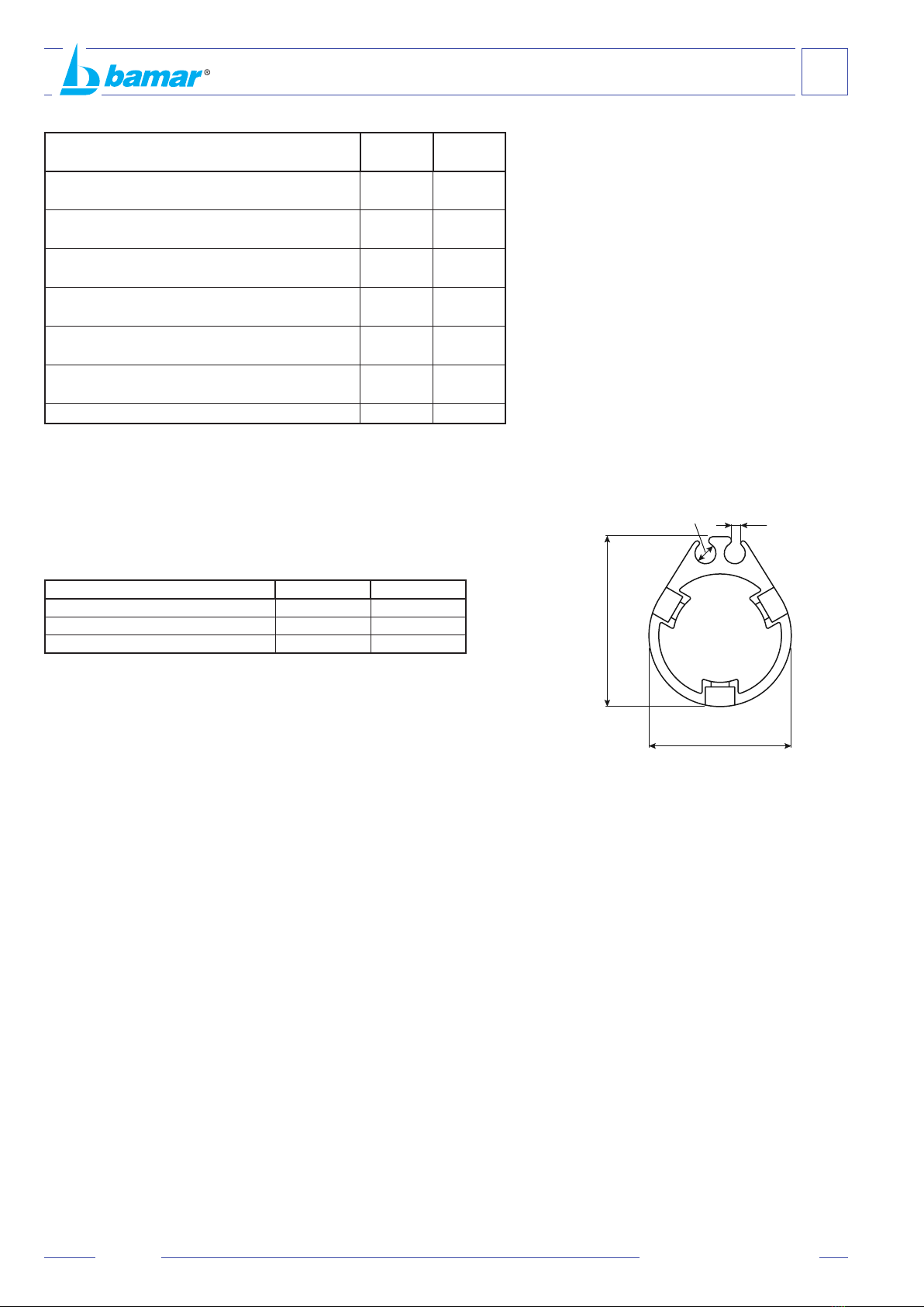
C-2 How to determine quantity and length of foils .16
C-3 How to prepare the BMG 52 foils ....................18
C-3.1 Cutting the terminal foil to measure ................18
C-3.2 Preparing the terminal foil ...............................19
C-4 Installing the furler with grounded stay............20
C-4.1 Terminal foil assembly scheme .......................20
C-4.2 Fitting connectors and half bearings ...............21
C-4.3 How to fit terminal foil, reinforcement
connectors, spacers and blocking ring............22
C-4.4 Fitting middle foils ...........................................23
C-4.5 Fitting the halyard swivel.................................24
C-4.6 Fitting the hoisting foil .....................................25
C-5 How to install the furler onboard .....................26
C-6 How to connect and adjust the turnbuckle ......26
C-7 How to install the motorization onto the
lower stay terminal ..........................................27
C-8 How to install the furler on armed mast...........27
C-9 Electric connection ..........................................28
C-10 Manual emergency clutch ...............................29
C-11 Suggestions for the sail...................................30
C-12 How to hoist the sail ........................................31
C-13 How to use the furler .......................................31
A INFORMAZIONI GENERALI ............................4
Introduzione ......................................................4
A-1 Simbologia presente nel manuale.....................5
A-2 Assistenza.........................................................5
A-3 Dati di identificazione ........................................6
A-3.1 Modello e tipo....................................................6
A-3.2 Costruttore ........................................................6
A-3.3 Targhetta di identificazione................................6
A-4 Imballo e contenuto...........................................7
A-5 Ricevimento del materiale.................................7
A-6 Attrezzatura minima necessaria........................8
A-7 Norme applicate ................................................8
A-8 Descrizione dell’apparecchiatura ......................8
A-9 Dati tecnici.........................................................9
A-9.1 EJF 3 - 3C .........................................................9
A-10 Impieghi ammessi ........................................... 11
A-11 Uso improprio.................................................. 11
B SICUREZZA....................................................12
B-1 Indicazioni generali .........................................12
C ISTRUZIONI DI MONTAGGIO........................13
C-1 Operazioni preliminari .....................................13
C-1.1 Terminale superiore dello strallo .....................13
C-1.2 Terminale inferiore dello strallo .......................13
C-1.3 Accessori per lo strallo in fune (opzionali).......14
C-1.4 Landa di prua ..................................................14
C- 1.4.1
Orientamento landa di prua.............................15
C-1.4.2Rotazione della forcella...................................15
C-1.5 Collegamenti elettrici.......................................15
C-2 Determinazione della quantità e della
lunghezza dei profili ........................................16
C-3 Preparazione al montaggio profili....................18
C-3.1 Taglio a misura del profilo terminale................18
C-3.2 Preparazione del profilo terminale ..................19
C-4 Montaggio dell’avvolgifiocco con
strallo a terra ...................................................20
C-4.1 Schema profilo terminale, giunti e distanziali ..20
C-4.2 Metodo di montaggio dei giunti e dei rinforzi...21
C-4.3 Montaggio di profilo terminale, giunti
di rinforzo, distanziali ed anello di fermo .........22
C-4.4 Montaggio dei profili intermedi .......................23
C-4.5 Montaggio della testa girevole ........................24
C-4.6 Montaggio del profilo inferitore........................25
C-5 Montaggio dell’avvolgifiocco in testa d’albero .26
C-6 Collegamento e regolazione del
tenditore dello strallo .......................................26
C-7 Fissaggio del riduttore per mezzo
del terminale inferiore del furler.......................27
C-8 Montaggio dell’avvolgifiocco con
albero armato ..................................................27
C-9 Collegamento elettrico ....................................28
C-10 Emergenza manuale .......................................29
C-11 Consigli per la vela..........................................30
C-12 Montaggio della vela .......................................31
C-13 Uso dell’avvolgifiocco......................................31
2UM_EJF_I-GB_rev. 3.0

INDICE GENERALE
GENERAL INDEX
I
© Copyright Soluzioni Meccaniche srl
Tutti i diritti riservati
Stampato in Italia
Realizzazione: Soluzioni Meccaniche srl - Forlì
Questo manuale o parti di esso non possono essere riprodotti, copiati o
divulgati con qualsiasi mezzo senza la preventiva autorizzazione scritta
della ditta Soluzioni Meccaniche srl.
La ditta Soluzioni Meccaniche srl si riserva il diritto di apportare in
qualsiasi momento tutte le modiche che riterrà opportune, nella costante
ricerca di migliorare la qualità e la sicurezza delle attrezzature, senza
impegnarsi ad aggiornare di volta in volta questa pubblicazione.
© Copyright Soluzioni Meccaniche srl
All rights reserved
Printed in Italy
Realization: Soluzioni Meccaniche srl - Forlì
No part of this manual may be reproduced, copied or transmitted
in any form, or by any means without permission in writing from
Soluzioni Meccaniche srl.
Soluzioni Meccaniche srl has the right to make any changes
they think necessary in order to improve the quality and safety
of the systems, without being obliged to revise this publication
every time.
D MAINTENANCE..............................................32
D-1 Maintenance....................................................32
D-2 Maintenance levels .........................................32
D-3 Maintenance programme ................................33
D-3.1 Cleaning and washing.....................................33
D-3.2 Long inactivity .................................................33
D-5 Troubleshooting...............................................34
D-3.3 Visual check ....................................................34
D-3.4 Repair..............................................................34
R SPARE PARTS ...............................................36
R-1 Motorization spare parts..................................36
TAV.1 Motorization main axis group ..........................37
TAV.2 Emergency clutch group .................................38
TAV.3 Torque tube group ...........................................39
TAV.4 Connection fork group.....................................40
TAV.6 BMG 90 - 110 foils...........................................42
WARRANTY....................................................44
D MANUTENZIONE ...........................................32
D-1 Manutenzione..................................................32
D-2 Livelli di manutenzione....................................32
D-3 Programma di manutenzione ..........................33
D-3.1 Pulizia e lavaggio ............................................33
D-3.2 Lunghi periodi di inutilizzo ...............................33
D-3.3 Verifiche visive ................................................34
D-3.4 Interventi di riparazione...................................34
D-4 Inconvenienti - cause - rimedi .........................34
R TAVOLA DELLE PARTI DI RICAMBIO ..........36
R-1 Parti di ricambio riduttore ................................36
TAV.1 Gruppo Asse motoriduttore .............................37
TAV.2 Gruppo emergenza .........................................38
TAV.3 Gruppo candela...............................................39
TAV.4 Gruppo forcella attacco landa .........................40
TAV.6 Profili BMG 90 - 110 ........................................42
GARANZIA .....................................................44
3
UM_EJF_I-GB_rev. 3.0

INTRODUZIONE
Questo manuale è stato realizzato allo scopo di fornire
tutte le informazioni necessarie per installare ed utilizzare
l’apparecchiatura in maniera corretta e sicura e per
effettuarne la manutenzione.
Occorre leggere e capire questo manuale
prima di usare l’apparecchiatura,
ed effettuare qualsiasi operazione
con esso o su di esso.
Il manuale è suddiviso in sezioni, capitoli e paragra in
modo da presentare le informazioni strutturate in modo
chiaro.
Le pagine sono numerate progressivamente.
La ricerca delle informazioni può essere basata sull’utilizzo
delle parole chiave usate come titolo delle sezioni e dei
capitoli ma soprattutto dalla consultazione dell’indice
generale.
Conservare questo manuale anche dopo la completa
lettura, in modo che sia sempre a portata di mano per il
chiarimento di eventuali dubbi.
In caso di problemi nella comprensione di questo manuale
o di parti di esso si raccomanda vivamente di contattare la
ditta Soluzioni Meccaniche srl: indirizzi, numeri di telefono
e telefax sono riportati nella quarta di copertina di questo
manuale.
La ditta Soluzioni Meccaniche srl declina ogni
responsabilità per danni a persone o cose
derivanti da un uso improprio dell’attrezzatura,
da imperizia, imprudenza o negligenza e dalla
inosservanza delle norme descritte in questo
manuale.
INTRODUCTION
This manual has been realised in order to supply all
required information for a correct and safe installation, use
and maintenance of the equipment.
You have to read and
understand this manual before using
the equipment and carrying out any
operation on it.
This manual has been divided into sections, chapters
and paragraphs in order to present the information in a
structured and clear way.
Pages are numbered progressively.
The search for information may be done either through the
key words used as titles for the sections, or through the
consultation of the general index.
Keep this manual at hand even after having read it, it may
help clarify any doubt.
Should you have problems in understanding this manual
or parts of it, we strongly recommend contacting Soluzioni
Meccaniche srl: address, phone and fax number can be
found on the cover.
Soluzioni Meccaniche srl declines any and every
responsibility for damages to persons or things
caused by either an improper use of the system
or inexperience, negligence, imprudence, or non-
compliance with this manual.
4
A
INFORMAZIONI GENERALI
GENERAL INFORMATION
UM_EJF_I-GB_rev. 3.0

A-1 SIMBOLOGIA PRESENTE NEL MANUALE
In questo manuale sono utilizzati cinque tipi di “simboli
graci di sicurezza”, che hanno lo scopo di evidenziare
altrettanti livelli di pericolo o informazione:
PERICOLO
PERICOLO DI FOLGORAZIONE
ATTENZIONE
AVVERTENZA
RISPETTA L'AMBIENTE
Richiama l'attenzione a situazioni o problemi che
potrebbero pregiudicare l'incolumità delle persone per
infortuni o rischio di morte.
PERICOLO
PERICOLO DI FOLGORAZIONE
ATTENZIONE
AVVERTENZA
RISPETTA L'AMBIENTE
Richiama l'attenzione ad una situazione di grave pericolo
che potrebbe pregiudicare l'incolumità delle persone
esposte no a possibili rischi di morte dovuti alla presenza
di tensione.
PERICOLO
PERICOLO DI FOLGORAZIONE
ATTENZIONE
AVVERTENZA
RISPETTA L'AMBIENTE
Richiama l'attenzione a situazioni o problemi connessi
con l'efcienza della macchina che non pregiudicano la
sicurezza delle persone.
PERICOLO
PERICOLO DI FOLGORAZIONE
ATTENZIONE
AVVERTENZA
RISPETTA L'AMBIENTE
Richiama l'attenzione a importanti informazioni di carattere
generale che non pregiudicano né la sicurezza personale,
né il buon funzionamento della macchina.
PERICOLO
PERICOLO DI FOLGORAZIONE
ATTENZIONE
AVVERTENZA
RISPETTA L'AMBIENTE
Per attirare l'attenzione verso importanti informazioni per
il rispetto dell'ambiente.
A-2 ASSISTENZA
Qualora ci siano dubbi sull’utilizzo o la manutenzione
dell’apparecchiatura, consigliamo di contattare la ditta
Soluzioni Meccaniche srl.
PERICOLO
PERICOLO DI FOLGORAZIONE
ATTENZIONE
AVVERTENZA
RISPETTA L'AMBIENTE
Nessuna modica deve essere apportata all’apparecchiatura
senza l’autorizzazione di Soluzioni Meccaniche srl, in
quanto può comportare pericoli.
A-1 SYMBOLS TO BE FOUND IN THE
MANUAL
Five “graphic safety symbols” are used in this manual.
Their purpose is to highlight different levels of danger and/
or information:
DANGER
DANGER OF ELECTROCUTION
CAUTION
WARNING
RESPECT THE ENVIRONMENT
Draws one’s attention to situations or problems that might
endanger the safety of persons, causing the risk of accident
and death.
DANGER
DANGER OF ELECTROCUTION
CAUTION
WARNING
RESPECT THE ENVIRONMENT
Draws one’s attention to a highly dangerous situation that
might endanger the safety and life of exposed persons due
to the presence of electricity.
DANGER
DANGER OF ELECTROCUTION
CAUTION
WARNING
RESPECT THE ENVIRONMENT
Draws one’s attention to situations or problems linked to
the system’s efciency which do not endanger the safety
of people.
DANGER
DANGER OF ELECTROCUTION
CAUTION
WARNING
RESPECT THE ENVIRONMENT
Draws one’s attention to important general information
that endangers neither personal safety nor the operation
of the system.
DANGER
DANGER OF ELECTROCUTION
CAUTION
WARNING
RESPECT THE ENVIRONMENT
Draws on s attention to important pieces of information
concerning respect for the environment.
A-2 AFTER-SALES SERVICE
Should you have any doubt concerning either the use or
maintenance of the equipment, we suggest contacting
Soluzioni Meccaniche srl.
DANGER
DANGER OF ELECTROCUTION
CAUTION
WARNING
RESPECT THE ENVIRONMENT
The equipment cannot be modied in any way without the
prior authorization from Soluzioni Meccaniche srl, as this
may be dangerous.
5
INFORMAZIONI GENERALI
GENERAL INFORMATION
A
UM_EJF_I-GB_rev. 3.0

A-3 DATI DI IDENTIFICAZIONE
Vericare che il manuale sia corrispondente alla macchina
a cui si fa riferimento.
Nel caso di richieste di informazione o di assistenza
tecnica, è necessario specificare, oltre al modello e
tipo di apparecchiatura, anche il numero di matricola
rilevabile dalla targhetta di identicazione posta su ogni
apparecchiatura.
A-3.1 Modello e tipo
Avvolgiocco elettrico tipo EJF:
• 3
• 3C
A-3.2 Costruttore
Soluzioni Meccaniche srl
Via F.lli Lumière 45
47122 FORLI’ - ITALY
Tel. +39 0543 463311
Fax. +39 0543 783319
www.bamar.it
info@bamar.it
A-3.3 Targhetta di identicazione
La targhetta di identificazione realizzata in alluminio
adesivo con fondo argento viene applicata direttamente
sull’apparecchiatura. In essa sono riportati i dati identi-
cativi dell’apparecchiatura e del costruttore:
A. Nome del costruttore
B. Dati costruttore
C. Marchio CE di conformità (ove presente)
D. Tipo di apparecchiatura
E. Modello
F. Anno di costruzione
G. Codice
A-3 IDENTIFICATION DATA
Please check the instruction manual corresponds to the
equipment we are referring to. Should you need further
information or technical assistance, you have to specify
not only model and type of equipment, but also the serial
number that you may nd on the identication plate placed
on every device.
A-3.1 Model and type
Electric foresail furler type EJF:
• 3
• 3C
A-3.2 Manufacturer
Soluzioni Meccaniche srl
Via F.lli Lumière 45
47122 FORLI’ - ITALY
Tel. +39 0543 463311
Fax. +39 0543 783319
www.bamar.it
info@bamar.it
A-3.3 Identication plate
The identication plate is made in adhesive aluminium with
silver background. It is tted directly onto the equipment.
The plate presents the identication data of both equipment
and manufacturer:
A. Name of manufacturer
B. Manufacturer data
C. CE conformity mark (where required)
D. Type of equipment
E. Model
F. Year of production
G. Code
Via F.lli Lumière 45 ● 47122 Forlì - ITALIA
Tel. +39 0543 463311 ● Fax +39 0543 783319
www.bamar.it
●
e-mail: info@bamar.it
Mod. Anno Codice
A B
C
D
E F G
6
A
INFORMAZIONI GENERALI
GENERAL INFORMATION
UM_EJF_I-GB_rev. 3.0

A-4 IMBALLO E CONTENUTO
Gli avvolgifiocco elettrici vengono forniti,completi
degli accessori per il montaggio, in robuste scatole,
sovrapponibili, di peso e dimensioni variabili in funzione
del modello e della lunghezza richiesta.
La confezione contiene:
A- n.1 Manuale uso e manutenzione
B - n.** Prolo intermedio L= 3000 mm
C- n.1 Snodo forcella-forcella (optional)
D- n.1 Corpo riduttore
E - n.1 Prolo inferitore
F- n.** Giunti di rinforzo
G- n.** Giunti intermedi
H- n.1 Anello terminale
I - n.1 Liquido frenaletti
J- n.1 Testa girevole + gambetti
K - n.** Viti per ssaggio giunti + chiave esagonale
L - n.1 Boccola di adattamento prolo
M- n.1 Perno
A-4 PACKAGING AND CONTENT
The electric foresail furling and reeng systems together
with all their accessories for the installation are supplied
in boxes of variable weight and dimensions depending on
model and length.
The boxes contain:
A- n.1 Use and Maintenance manual
B- n.** Middle foils L= 3000 mm
C- n.1 Fork-fork toggle (optional)
D- n.1 Furler motorization
E- n.1 Hoisting foil
F- n.** Reinforcement connectors
G- n.** Middle connectors
H- n.1 Blocking ring
I- n.1 Sealing liquid tube
J- n.1 Halyard swivel + shackles
K- n.** Screws for xing splice pieces + Allen wrench
L- n.1 Tack adapter
M- n.1 Pin
A-5 RICEVIMENTO DEL MATERIALE
Dimensioni e peso dell'imballo
PERICOLO
PERICOLO DI FOLGORAZIONE
ATTENZIONE
AVVERTENZA
RISPETTA L'AMBIENTE
Le dimensioni ed il peso dell’imballo cambiano a seconda
del contenuto della scatola.
La merce viaggia a rischio e pericolo del destinatario. Egli ha
il dovere di eseguire una completa verica di quanto ricevuto,
emettere tutte le riserve, se necessario esercitare tutti i ricorsi
al trasportatore nei termini e nei modi regolamentari.
A-5 RECEIPT OF GOODS
Packaging dimensions and weight
DANGER
DANGER OF ELECTROCUTION
CAUTION
WARNING
RESPECT THE ENVIRONMENT
Packaging weight and dimensions vary depending on box
content.
The goods are shipped at the receiver’s own risk. The
purchaser will have to check the goods carefully and should
claim from the carrier in the due terms.
** le quantità dipendono dalla lunghezza richiesta ** quantities depend on the length required
7
INFORMAZIONI GENERALI
GENERAL INFORMATION
A
UM_EJF_I-GB_rev. 3.0
B
C
D
J
E
F
I
L
A
M
K
GH

A-6 ATTREZZATURA MINIMA NECESSARIA
PERICOLO
PERICOLO DI FOLGORAZIONE
ATTENZIONE
AVVERTENZA
RISPETTA L'AMBIENTE
Evitare nel modo più assoluto di dare corso al montaggio
senza avere a disposizione l’attrezzatura necessaria. Il
procedere con attrezzi di fortuna può, oltreché danneggiare
irreparabilmente l’apparecchiatura, risultare pericoloso per
l’incolumità generale.
Prima di iniziare le operazioni di montaggio è bene
accertarsi di disporre di una serie di attrezzi, di seguito
elencati, quale attrezzatura minima necessaria:
• Cacciavite con testa a croce ø 5 mm.
• Martello di plastica.
• Pinza.
• Punta da segno.
• Trapano elettrico con mandrino per punte elicoidali ø
7 mm.
• Seghetto a mano con lama per taglio di metalli.
• Lima a taglio ne.
• Punte elicoidali per la foratura di metallo.
• Set di chiavi a brugola.
A-7 NORME APPLICATE
Per la sicurezza dell’operatore, nell’analisi dei rischi del
EJF, sono state considerate le seguenti norme:
Direttiva Titolo
89/336 CEE Compatibilità elettromagnetica
73/23 CE Bassa tensione
A-8 DESCRIZIONE
DELL’APPARECCHIATURA
EJF nasce da una combinazione fra tecnologia e design.
L’evoluzione della tecnologia nel settore della vela è
sempre più rivolta verso meccanismi servoassistiti di
altissima qualità, performance e afdabilità.
Bamar propone questa nuova linea di avvolgitori elettrici
che garantiscono prestazioni uniche quali capacità di tiro
maggiori, sincronismo fra più movimenti, manutenzione
ridottissima, semplicità nelle installazioni, che migliorano
il comfort e la sicurezza a bordo.
L’avvolgimento reversibile è basato su un meccanismo
epicicloidale ad alto rendimento, mentre un freno elettro-
magnetico (E/M) ne garantisce il blocco meccanico sia
dopo il completo avvolgimento che in posizione vela
terzarolata.
A-6 BASIC TOOLS
DANGER
DANGER OF ELECTROCUTION
CAUTION
WARNING
RESPECT THE ENVIRONMENT
Avoid starting to assemble the equipment without the
required tools. Proceeding with the wrong tools may
not only irremediably damage the system, but also be
dangerous for general safety.
Before starting to assemble the system make sure you
have the following basic series of tools:
• Star screw driver ø 5 mm.
• Plastic hammer.
• A pair of pliers.
• Mark bit.
• Electric drill with mandrel for ø 7 mm. drill bits.
• Hand metal saw.
• Smooth le.
• Drill bits for drilling metal.
• Allen key set.
A-7 RULES TO BE APPLIED
For the operator’s safety, we have considered the following
rules in the risk analysis of EJF:
Rule Title
89/336 EEC Electromagnetic compatibility
73/23 EC Low tension
A-8 DESCRIPTION OF THE EQUIPMENT
EJF has been developed combining technology and
design. The evolution of technology in the sailing
world grows more and more towards semi- automatic
mechanisms satisfying performance, reliability and quality.
Bamar presents this new line of electric Jib Furlers which
guarantees unique specications, increased torque force,
easy installation, synchronism between movements, low
maintenance, thus improving comfort and safety onboard.
The EJF reversible Jib Furler is based on a epicyclic
mechanism to obtain high performance efciency,
whereas a magnetic brake (E/M) guarantees the
mechanical lock either after complete furling in, or in any
reefed sail position.
8
A
INFORMAZIONI GENERALI
GENERAL INFORMATION
UM_EJF_I-GB_rev. 3.0

C
BA
Swivel
ø wire / ROD
ø pin
D
F
I
O
P
Q
N
ML
K
E
J
R
G
H
* Check whether the eye terminal can be disassembled in order to have the
stay pass through the foils (see Ø m).
** If the stay lower connection is supplied with a standard slide inside the furler’s
foils. On the contrary, should the stay have a bigger terminal, you need to check
that its dimensions are not bigger than the internal diameter of the foils. In
such case you will need to replace the terminal with a Stalok-type of terminal.
* Vericare che il terminale ad occhio sia smontabile e passi all’interno del prolo
(vedi ø m).
**
Se lo strallo è munito, alla sua estremità verso coperta, di un cannotto lettato
a pressare di tipo commerciale, non ci saranno difcoltà a far scorrere questo
elemento all’interno dei proli dell’avvolgiocco. Diversamente, con terminali più
ingombranti, vericare che le dimensioni del terminale non siano superiori a quelle
del diametro interno dei proli. In questo caso sarà necessario eliminare il terminale
e ripiombare, dopo il montaggio dei proli, con un terminale rapido tipo Sta-lok.
A-9 DATI TECNICI
A-9.1 EJF 3 - 3C
ROD # (*)
-115 -150
ø Fune 1x19 mm (**)
1x19 mm Wire ø (**)
28 32
Max vela (150%) m2
Max sail area (150%) sq.m
250 290
A
282 321
B
250 290
ø C
109 129,5
D
3000 3000
E
1500 1500
ø F
134 134
ø G
104 104
ø H
133 133
I
1501 1501
ø J
20 20
K
1685 -
L
701 701
M
471 471
N
108 108
O
440 440
P
298 298
Q
108 108
R
196 196
ø pin
39,5 44,5
Swivel peso
Swivel weight kg
9,9 15,8
Profilo peso
Foil weight kg/m
4,02 5,6
Motorizzazione peso kg
Motorization weight
120 195
Profilo - Foil BMG
90 110
Max carico lavoro swivel kg
Swivel max working load
8000 10000
A-9 TECHNICAL DATA
A-9.1 EJF 3 - 3C
9
INFORMAZIONI GENERALI
GENERAL INFORMATION
A
UM_EJF_I-GB_rev. 3.0

Caratteristiche tecniche motorizzazione
Motorization technical characteristics EJF 3 EJF 3C
Potenza motore elettrico W
Electric motor power 1500 1500
Velocità max prolo RPM
Max foil speed 35 35
Alimentazione elettrica V
Electric supply 24 24
Assorbimento nominale A
Rated absorption - -
Possibilità di utilizzo con vela terzarolata
Use with refeed sail SÌ SÌ
Coppia nominale su prolo Nm
Rated torque on foil 350 350
Servizio - Service S2-15’ S2-15'
BMG 90 BMG 110
sezione - section AxB mm 80x90 100x110
canaletta -
sail groove
(C) mm ø 8 ø 9
apertura - gap (D) mm 3,5 3
Sezione prolo connettore e boccola di rotolamento
Foil and splice piece section
AA
A
B B
B
D
C
D
D
C
C
10
A
INFORMAZIONI GENERALI
GENERAL INFORMATION
UM_EJF_I-GB_rev. 3.0
BMG 90 - 110

A-10 IMPIEGHI AMMESSI
L’avvolgiocco elettrico è una specica attrezzatura per
l’avvolgimento della vela di prua su imbarcazioni da diporto
o da crociera.
Qualsiasi altro impiego viene considerato contrario all’uso
previsto e pertanto improprio.
La conformità ed il rigoroso rispetto delle condizioni d’uso,
manutenzione e riparazione specicate dal costruttore,
costituiscono una componente essenziale dell’uso previsto.
L’uso, la manutenzione e la riparazione dell’avvolgiocco
debbono essere afdate esclusivamente a persone a
conoscenza delle sue peculiarità e delle relative procedure
di sicurezza.
È inoltre necessario che siano rispettate tutte le norme
antinfortunistiche e le norme generalmente riconosciute
per la sicurezza e la medicina del lavoro.
A-11 USO IMPROPRIO
Per uso improprio si intende l’uso dell’apparecchiatura
secondo criteri di lavoro non conformi alle istruzioni
contenute in questo manuale e che, comunque, risultassero
pericolosi per sè e per gli altri.
PERICOLO
PERICOLO DI FOLGORAZIONE
ATTENZIONE
AVVERTENZA
RISPETTA L'AMBIENTE
La ditta Soluzioni Meccaniche srl declina ogni responsabilità
per incidenti a persone o cose derivanti dalla inosservanza
delle disposizioni ed istruzioni elencate nel presente
manuale e dalla inosservanza delle norme di sicurezza e
prevenzione infortuni vigenti nei vari paesi.
PERICOLO
PERICOLO DI FOLGORAZIONE
ATTENZIONE
AVVERTENZA
RISPETTA L'AMBIENTE
Se l’apparecchiatura viene utilizzata in modo diverso
dal consentito, l’operatore è responsabile della propria
sicurezza e di quella delle persone eventualmente
coinvolte.
A-10 PROPER USE
The electric foresail furling system is to be used for furling
and reeng the foresail on cruising boats.
Any other use is considered as contrary to the proper use
and therefore not allowed.
The conformity and the rigorous respect of the conditions of
use, maintenance and repair specied by the manufacturer,
are an essential component of the proper use.
The use, maintenance and repair of the furler have to be
carried out exclusively by people who know it speculiarities
and safety procedures.
Moreover, all safety rules have to be followed.
A-11 WRONG USE
Wrong use indicates the use of the device following working
criteria that do not correspond to the instructions presented
in this manual and that might be dangerous for the operator
himself and other people.
DANGER
DANGER OF ELECTROCUTION
CAUTION
WARNING
RESPECT THE ENVIRONMENT
Soluzioni Meccaniche srl declines any and every
responsibility for accidents to persons or things deriving
from the non-compliance with both the dispositions and
instructions listed in the present manual and the rules on
safety and accident prevention in force in the different
countries.
DANGER
DANGER OF ELECTROCUTION
CAUTION
WARNING
RESPECT THE ENVIRONMENT
Should the equipment be used in an improper way, the
operator is responsible for his/her own safety and for the
persons that may be involved.
11
INFORMAZIONI GENERALI
GENERAL INFORMATION
A
UM_EJF_I-GB_rev. 3.0

B-1 GENERAL INDICATIONS
This chapter summarises the general safety indications
that will be integrated in the following chapters by specic
tips when necessary.
Though the system is very simple to assemble and use,
some basic safety rules have to be followed. These rules
will grant both the safety of the operator and the correct
use of the product for its best preservation in time.
DANGER
DANGER OF ELECTROCUTION
CAUTION
WARNING
RESPECT THE ENVIRONMENT
If the furler is assembled on an armed mast it isnecessary
the co-operation of two operators is required. The operator
who works on the mast head needs an adequate safety
harness to prevent him from falling.
• Carefully read and understand the instruction manual
before installing and starting the furler.
• The equipment must never be used by children,
and must not be employed for uses that are not
contemplated in this manual.
• All tasks have to be carried out wearing adequate
clothes that abide the Laws in force in the Country
where the job is done.
• Always keep this manual handy. Read it carefully in
order to learn the instructions for both installation and
use.
• Do not allow people who do not have the necessary
knowledge to use the system.
• Carry out the installation and maintenance in optimal
conditions of visibility and in areas that are suitable for
all necessary operations both for climate and collocation
of the plane of work.
• Should the interventions be inevitably executed
onboard, carry them out only when the conditions can
grant the highest safety.
• Do not carry out the installation in case of strong wind
or rainstorm.
• Do not execute any intervention in presence of persons
that for either age or psycho-physical conditions can not
grant the necessary common sense.
B-1 INDICAZIONI GENERALI
Questo capitolo riassume le indicazioni di sicurezza di
carattere generale che saranno integrate, nei capitoli
seguenti, da speciche avvertenze ogni qualvolta dovesse
risultare necessario.
Nonostante l’estrema semplicità delle operazioni di
montaggio e la facilità nell’uso dell’attrezzatura, è
opportuno che vengano rispettate alcune elementari
norme di sicurezza. Queste norme garantiranno, oltre
all’incolumità sica dell’operatore, un corretto uso del
prodotto ed una sua ottimale resa nel tempo.
PERICOLO
PERICOLO DI FOLGORAZIONE
ATTENZIONE
AVVERTENZA
RISPETTA L'AMBIENTE
Nel caso in cui il montaggio dell’avvolgifocco sia effettuato
su di un albero già armato sull’imbarcazione è necessario
l’intervento di almeno due operatori. L’operatore destinato
ad intervenire in testa d’albero dovrà essere munito di
adeguata imbragatura di sicurezza (“banzigo”) contro il
rischio di cadute.
• Leggere attentamente e comprendere le istruzioni per
l’uso prima di procedere all’installazione ed alla messa
in funzione dell’attrezzatura.
• L’attrezzatura non deve in alcun modo essere utilizzato
da bambini o per impieghi diversi da quelli specicati
nel presente manuale.
• Tutti i lavori devono essere eseguiti indossando
indumenti adeguati alle condizioni del lavoro stesso,
ed ottemperanti alle norme vigenti nel paese nel quale
tali lavori vengono eseguiti.
• Tenere questo manuale sempre a portata di mano
e conservarlo con cura. Leggerlo attentamente per
apprenderne le istruzioni relative sia al montaggio che
all’uso.
• Evitare che persone non a conoscenza delle necessarie
informazioni possano intervenire sull’attrezzatura.
• Eseguire le operazioni di montaggio e manutenzione
in condizioni ottimali di visibilità ed in ambienti che, per
clima e collocazione ergonomica del piano di lavoro,
possano risultare idonei allo svolgimento di tutte le
operazioni necessarie.
• Qualora gli interventi debbano necessariamente
avvenire sull’imbarcazione, effettuarli soltanto quando
le condizioni climatiche possano garantire la massima
sicurezza.
• Non eseguire l’installazione in caso di forte vento o di
temporali.
• Non eseguire mai alcun intervento (operativo o
manutentivo) in presenza di persone che per età o
condizione psicosica non siano in grado di garantire
il necessario buonsenso.
B
SICUREZZA
SAFETY
12 UM_EJF_I-GB_rev. 3.0

C-1 OPERAZIONI PRELIMINARI
Aprire gli imballi e vericare che la dotazione di materiali
e minuterie sia completa.
PERICOLO
PERICOLO DI FOLGORAZIONE
ATTENZIONE
AVVERTENZA
RISPETTA L'AMBIENTE
Provvedere allo smaltimento dell’attrezzatura secondo le
normative vigenti nei vari paesi.
PERICOLO
PERICOLO DI FOLGORAZIONE
ATTENZIONE
AVVERTENZA
RISPETTA L'AMBIENTE
Prima di procedere all’installazione dell’avvolgifiocco
vericate o fate vericare da persona competente che
lo strallo sia in buone condizioni. In caso di dubbio è
consigliabile sostituirlo.
C-1.1 Terminale superiore dello strallo
Non tutti i terminali superiori degli stralli sono idonei
al montaggio di un avvolgifiocco per cui si rendono
necessarie alcune modiche allo strallo nel caso in cui si
effettui il montaggio con strallo a terra.
• Terminali a sfera (principalmente presenti su alberi
Isomat e Z-spars).
Occorre inserire un terminale a sfera-occhio tipo Acmo
EB o equivalenti in testa d’albero, accorciare il cavo
tenendo conto della lunghezza del nuovo pezzo ed
aggiungere un nuovo terminalea pressare sullo strallo.
• Terminali a T (principalmente presenti su alberi Kemp,
Selden, Nemo, Sparcraft con sartiame frazionato).
Occorre modicare l’ancoraggio dello strallo sull’albero
per poter impiegare un terminale a pressare con snodo.
C-1.2 Terminale inferiore dello strallo
PERICOLO
PERICOLO DI FOLGORAZIONE
ATTENZIONE
AVVERTENZA
RISPETTA L'AMBIENTE
SU STRALLI ESISTENTI: Prima di iniziare l’installazione
marcare sullo strallo la posizione di regolazione del
tenditore (se previsto) e/o la posizione dell’occhio inferiore
dello strallo tra le lande.
CON UNO STRALLO NUOVO: montare lo strallo
sull’imbarcazione, eseguire la regolazione del tenditore e
marcarne la regolazione.
Se lo strallo è munito, alla sua estremità verso coperta, di
un cannotto lettato a pressare di tipo commerciale, non ci
saranno difcoltà a far scorrere questo elemento all’intemo
dei proli dell’avvolgiocco. Diversamente, con terminali
più ingombranti, vericare che le dimensioni del terminale
non siano superiori a quelle del diametro interno dei proli
(vedi cap. A-9). In questo caso sarà necessario eliminare
il terminale e ripiombare, dopo il montaggio dei proli, con
un terminale rapido tipo STA-LOK®o simili.
C-1 PRELIMINARY OPERATIONS
Open all boxes and check the list of materials is complete.
DANGER
DANGER OF ELECTROCUTION
CAUTION
WARNING
RESPECT THE ENVIRONMENT
Dispose of the equipment following the rules in force in
the different countries.
DANGER
DANGER OF ELECTROCUTION
CAUTION
WARNING
RESPECT THE ENVIRONMENT
Before installing the furler, check the stay is in good
conditions. In case of doubt we suggest replacing it.
C-1.1 Stay upper terminal
Not all upper terminals are suitable for the tting of an
electric foresail furling and reeng system, therefore some
modications to the stay are necessary if the installation
has to be carried out with grounded stay.
• Ball terminals (mainly present on Isomat and Z-spars
masts).
You will have to add a ball-eye terminal (Acmo EB type)
or similar on the mast head, shorten the stay keeping in
mind the length of the new piece,and add a new swage
terminal to the stay.
• T terminals (mainly on Kemp, Selden, Nemo,
Sparcraft masts with fractional rig). You need to modify
the stay connection to the mast in order to use a toggle
swage terminal.
C-1.2 Stay lower terminal
DANGER
DANGER OF ELECTROCUTION
CAUTION
WARNING
RESPECT THE ENVIRONMENT
ON EXISTING STAYS: before starting the installation, mark
the position of the turnbuckle (if any) on the stay, and/or the
position of the lower eye terminal between the link plates.
ON A NEW STAY: install the stay on to the mast, adjust
the turnbuckle and mark its adjustment.
If the forestay is supplied with a standard swage threaded
terminal on its lower end, there will be no problem in letting
this element slide inside the furler foils. On the contrary,
with bigger terminal, check the terminal dimensions are not
bigger than the foil internal diameter (see chapt. A-9). In
this case, you will have to take off the terminal and replace
it with a swage less terminal (STA-LOK®type) after having
installed the foils.
ISTRUZIONI DI MONTAGGIO E USO
INSTALLATION AND USE
C
13
UM_EJF_I-GB_rev. 3.0

C-1.3 Accessori per lo strallo in fune (opzionali)
Terminali ed accessori speciali per la semplicazione
dell’installazione:
1. Perno speciale per bloccare il tenditore allo snodo ad
occhio o forcella dello strallo.
2. Snodo fork-fork (ricavato da barra) per tenditore
snodato.
C-1.3 Wire stay accessories (optional)
Terminals and special accessories which make the
installation easier:
1. Special clevis pin to lock the turnbuckle onto an eye/
fork or fork/fork toggle.
2. Fork/fork bar toggle for turnbuckle.
Max FUNE Ø / Ø Max WIRE perno Ø / Ø pin (1) (2)
28 39,5 901101360 custom
32 44,5 901101365 custom
C-1.4 Landa di prua
Il corpo riduttore dell’avvolgiocco deve essere ancorato
alla landa di prua tramite il perno speciale specicando il
diametro del perno.
La posizione di attacco deve essere scelta in funzione di:
• Manovrabilità del braccio ancora.
• Possibilità di alloggiare all’interno il tenditore,previa
verica degli ingombri del tenditore.
C-1.4 Chain plate
The motorization has to be connected to the chain plate
by means of a special clevis pin (the pin diameter has to
be specied).
The anchoring position has to be chosen depending on:
• Handling of the anchor.
• Possibility of lodging the turnbuckle inside the furler,
after having checked its dimensions.
A B
Perno speciale e n°
2 dadi a corona
Special clevis pin
and nr. 2 nylock
nuts
N.B.: è importante che l’ancoraggio della motorizzazione
includa uno snodo (forcella-forcella) ricavato da barra. Lo
snodo, infatti, costituisce un importante elemento anti-
rotazione quando la vela viene ridotta e si effettuano i
terzaroli.
A. Utilizzo di uno snodo forcella-forcella e perno speciale
per ancoraggio strallo con tenditore con terminale ad
occhio.
B. Utilizzo di uno snodo forcella-forcella e perno speciale
per ancoraggio strallo con terminale ad occhio.
N.B.: when you anchor the motorization to the chain-plate
you have to make use of a bar toggle (fork-fork toggle). In
fact, the toggle is an important anti-rotation element when
the sail is reefed.
A. Use of a fork-fork toggle and special clevis pin to
anchor the stay tted with a turnbuckle with eye
terminal.
B. Use of a fork-fork toggle and special clevis pin to
anchor a stay tted with an eye terminal.
C
ISTRUZIONI DI MONTAGGIO E USO
INSTALLATION AND USE
14 UM_EJF_I-GB_rev. 3.0

C-1.4.2 Rotazione della
forcella
• Svitare i tre grani (A).
• Svitare la angia (B).
• Spingere la forcella (C) verso
l'alto per slare le spine interne
dalla loro sede.
• Ruotare la forcella (C) di 90°.
• Assicurarsi che le spine siano
allineate con la loro sede e
tirare verso il basso la forcella
(C).
• Riavvitare la angia (B).
• Riavvitare i tre grani (A).
C-1.4.2 How to rotate the
furler's fork
• Unscrew the 3 grub screws (A).
• Unscrew ange (B).
• Pull the fork element (C) up in
order to have its pins slide out
from their seats.
• Rotate the fork element (C)
by 90°.
• Make sure the pins are in line
with their new seats and pull
down the the fork element (C).
• Screw in ange (B).
• Screw in the 3 grub screws (A).
Electric
motor Brake
Red Black
Brown
Positive
+
Blue
Negative
-
Thermic Sensor
Brown Blue
EJF 3
C-1.5 Collegamenti elettrici
PERICOLO
PERICOLO DI FOLGORAZIONE
ATTENZIONE
AVVERTENZA
RISPETTA L'AMBIENTE
Il freno elettromeccanico è polarizzato.
Per i collegamenti elettrici vedere istruzioni sul manuale
E14S.
C-1.5 Electric connection
DANGER
DANGER OF ELECTROCUTION
CAUTION
WARNING
RESPECT THE ENVIRONMENT
The electro-mechanic brake is polarized.
For electric wiring please refer to Boxtron manual.
C- 1.4.1 Orientamento landa di prua
Prima di procedere con l’installazione, controllare
l’orientamento della landa di prua.
La forcella inferiore della motorizzazione EJF è orientabile
di 90°, quindi nel caso in cui si richiedesse una differente
installazione, basterà seguire le istruzioni qui di seguito
riportate al punto C1.4.2.
C- 1.4.1 Deck chain-plate alignment
Before you start assembling the system onboard, we kindly
ask you to check the chain-plate alignment.
The EJF Motorization lower fork can be rotated by 90°.
Therefore, should you require a different tting, you will
just need to follow the instructions shown hereafter at
section C1.4.2.
ISTRUZIONI DI MONTAGGIO E USO
INSTALLATION AND USE
C
15
UM_EJF_I-GB_rev. 3.0
A
C
B

C-2 DETERMINAZIONE DELLA QUANTITÀ E
DELLA LUNGHEZZA DEI PROFILI
Al ne di poter determinare la quantità dei proli necessari
occorre, dopo aver denito la posizione di attacco sulla
landa del corpo motoriduttore, procedere come segue:
• Vericare la lunghezza Adello strallo dal centro del
foro di attacco sulla landa alla piombatura del terminale
superiore.
• Scegliere nella tabella della pagina seguente la misura
Win funzione del foro utilizzato sulla landa.
Applicare la seguente formula:
Dove:
A è lunghezza dello strallo misurata dal centro del foro
di attacco sulla landa alla piombatura del terminale
superiore
W è la misura dal centro del foro di attacco sulla landa
alla base di partenza del prolo inferitore
X è la lunghezza del prolo inferitore:
150 distanza ssa tra terminale e piombatura strallo
3000 lunghezza di un prolo intermedio.
Vediamo un esempio pratico:
• Lunghezza Adello strallo 38000 mm
• Lunghezza W1371 mm
Applichiamo la formula:
Si dovranno quindi utilizzare 11 proli interi ed accorciare
un dodicesimo prolo alla lunghezza di 1950 mm.
Vedere il capitolo C-3 Preparazione al montaggio per la
corretta procedura per il taglio del prolo.
C-2 HOW TO DETERMINE QUANTITY AND
LENGTH OF FOILS
In order to determine the number of foils required, you must
proceed as follows, after having dened the connection
on the link plates.
• Check the stay length A, from the connection pin hole
on the link plate, to the upper terminal swaging.
• On the next page you will nd a table concerning the
furler measures. Find out the length of Won your furler
depending on the hole you will use on the link plate.
• Apply the following formula:
Where:
A is the length of the stay from the connection pin
hole on the plate to the upper terminal swaging
W is the measure from the centre of the connection
pin hole on the plate to the beginning of the hoisting
foil
X is the length of the hoisting foil:
150 xed distance from terminal to stay swage
3000 length of a middle foil.
Let’s see a practical example:
• Length of the stay A 38000 mm
• Length of W1371 mm
Now, let’s apply the formula:
This means you will have to use 11 foils and cut the 12th
one to length (1950 mm).
Please, see the section C-3 How to prepare the foil’s for
the correct procedure when cutting the foil.
A-(W+X+150)
3000 = Numero dei proli
38000-(1371+1500+150)
3000 = 11,65
N° Proli
65% della lunghezza
di un prolo
38000-(1371+1500+150)
3000 = 11,65
N° Foils
65% of length
of a foil
A-(W+X+150)
3000 = Number of foils
C
ISTRUZIONI DI MONTAGGIO E USO
INSTALLATION AND USE
16 UM_EJF_I-GB_rev. 3.0

X
Y
Z
W
M
A
L
L
Ø Fune mm
Ø Wire mm
L mm
Fork-Fork
28 -
32 220
Snodo / Toggle
BMG 90, BMG 110
X = 1500 mm
Z = 3000 mm **
Y = 3000 mm
** Da tagliare a misura
** To be cut to measure
EJF 3.01 M= 701 mm
A-(W+X+150*)
3000 =Numero dei proli
Number of foils
ISTRUZIONI DI MONTAGGIO E USO
INSTALLATION AND USE
C
17
UM_EJF_I-GB_rev. 3.0

C-3 PREPARAZIONE AL MONTAGGIO
PROFILI
C-3.1 Taglio a misura del
prolo terminale
• Tracciare su un profilo la misura
ricavata dalla formula dal cap. C-2.
• Tagliare con un seghetto a mano il
prolo.
• Con una lima a taglio dolce sbavare
le estremità del prolo con particolare
cura le sedi del gratile.
C-3 HOW TO PREPARE THE BMG 52 FOILS
C-3.1 Cutting the terminal foil to
measure
• Mark out on a foil the measure you
derived from the formula on chapt.
C-2.
• Cut the foil with a hand saw.
• File the foil end with a smooth
le with particular care to the luff
groove.
C
ISTRUZIONI DI MONTAGGIO E USO
INSTALLATION AND USE
18 UM_EJF_I-GB_rev. 3.0

C-3.2 Preparazione del prolo
terminale
• Montare l’anello di fermo sul prolo
terminale.
• Segnare sul profilo la posizione
dei fori corrispondente a quelli
sull’anello di fermo.
• Realizzare una nicchia con la punta
del trapano ø 6 mm in corrispondenza
dei fori lettati per una profondità
massima di 2 mm.
C-3.2 Preparing the terminal
foil
• Fit the blocking ring onto the terminal
foil.
• Mark on the foil the position of the
holes corresponding to the ones on
the blocking ring.
• Make a 2 mm. deep niche with the
ø 6 mm. bit in correspondence with
the threaded holes.
ISTRUZIONI DI MONTAGGIO E USO
INSTALLATION AND USE
C
19
UM_EJF_I-GB_rev. 3.0

C-4 MONTAGGIO DELL’AVVOLGIFIOCCO
CON STRALLO A TERRA
Smontare lo strallo ed appoggiarlo su una supercie adatta
al montaggio avendo cura di accertarsi che l’avvolgiocco
ed i proli non si danneggino in corso d’opera.
PERICOLO
PERICOLO DI FOLGORAZIONE
ATTENZIONE
AVVERTENZA
RISPETTA L'AMBIENTE
Prima di smontare lo strallo assicurarsi che sia stata
applicata una drizza di sicurezza a prua.
C-4 INSTALLING THE FURLER WITH
GROUNDED STAY
Take down the stay and put it on an even surface. Take
care not to damage neither motorization nor foils during
the installation.
DANGER
DANGER OF ELECTROCUTION
CAUTION
WARNING
RESPECT THE ENVIRONMENT
Before taking down the stay make sure you have put a
safety halyard to replace it.
C-4.1 Terminal foil assembly scheme
C-4.1 Schema prolo terminale, giunti e
distanziali
Prolo
Foil A* B C D**
BMG 90 2040 200 300 3000
BMG 110 1990 500 350 3000
Giunto
Connector
Giunto
Connector
Distanziale
Spacer
Giunto
Connector
Distanziale da tagliare
Spacer to be cut
B
A
D
B
C
* Il distanziale in alluminio lungo “A” deve essere tagliato
a misura. La misura del taglio deve equivalere al
quantitativo tagliato dal prolo terminale “D” (esempio:
vedi formula pratica).
** Prolo intermedio da tagliare a misura.
* The aluminium spacer “A” has to be cut to measure.
The cut has to have the same length as the portion that
has been cut off from the terminal foil “D” (see formula
for practical example).
** Middle foil to be cut to measure.
C
ISTRUZIONI DI MONTAGGIO E USO
INSTALLATION AND USE
20 UM_EJF_I-GB_rev. 3.0
This manual suits for next models
2
Table of contents
Other bamar Marine Equipment manuals
Popular Marine Equipment manuals by other brands

Teknim
Teknim TFS-1192R installation manual

Seastar Solutions
Seastar Solutions ABYC CHX8000 Series installation instructions

Venitem
Venitem HEMA L Technical manual

CRUISING ELECTRONICS
CRUISING ELECTRONICS ER-66S instructions

E2S
E2S SONFL1H Series Instructions/service manual

Ziton
Ziton ZP755B-2 Installation sheet