BEGA 84 789 User manual

BEGA Gantenbrink-Leuchten KG · Postfach 31 60 · 58689 Menden · info@bega.com · www.bega.com 1/4
33.18 · Technische Änderungen vorbehalten · Technical amendments reserved · Modications techniques réservées
!
Raster
Louvre
Grille de délement
71 119
Ø 125Ø 125 2020
Gebrauchsanweisung Instructions for use Fiche d’utilisation
Anwendung
Das innenliegende Raster verhindert den
seitlichen Einblick bis 45° aus allen Richtungen.
Passend zu Leistungsscheinwerfer:
84 209 · 84 216 · 84 662
Eine kombinierte Verwendung von Raster und
Streuscheibe ist nicht möglich.
Passend zu Bodeneinbauscheinwerfer:
84 789 · 84 800 · 84 899
Application
The internal louver prevents a lateral glare from
all directions up to 45°.
Suitable for performance oodlight:
84 209 · 84 216 · 84 662
It is not possible to use a combination of louvre
and diffuser disk.
Suitable for in-ground oodlight:
84 789 · 84 800 · 84 899
Utilisation
La grille de délement installée derrière le verre
empêche le contact visuel latéral jusqu'à 45°
quelque soit la direction.
Pour projecteur puissant :
84 209 · 84 216 · 84 662
L’utilisation simultanée d’une grille et d‘une
lentille n’est pas possible.
Pour projecteur à encastrer :
84 789 · 84 800 · 84 899
Produktbeschreibung
Raster innenliegend
aus Kunststoff
Farbe schwarz
c – Konformitätszeichen
Gewicht: 0,05 kg
Product description
Inside louvre made of polyamide
Colour black
c – Conformity mark
Weight: 0.05 kg
Description du produit
Grille de délement intérieure en matière
synthétique
Couleur noire
c – Sigle de conformité
Poids: 0,05 kg
Sicherheit
Der Hersteller übernimmt keine Haftung für
Schäden, die durch unsachgemäßen Einsatz
oder Montage entstehen.
Werden nachträglich Änderungen an dem
Ergänzungsteil vorgenommen, so gilt derjenige
als Hersteller, der diese Änderungen vornimmt.
Safety indices
The manufacturer is then discharged from
liability when damage is caused by improper
use or installation.
If any accessory is subsequently modied, the
persons responsible for the modication shall
be considered as manufacturer.
Sécurité
Le fabricant décline toute responsabilité
résultant d’une mise en œuvre ou d’une
installation inappropriée du produit.
Toutes les modications apportées à cet
accessoire se feront sous la responsabilité
exclusive de celui qui les effectuera.

BEGA Gantenbrink-Leuchten KG · Postfach 31 60 · 58689 Menden · info@bega.com · www.bega.com
2/4
Montage Leistungsscheinwerfer
84 209 · 84 216 · 84 662
Scheinwerfer öffnen:
Verriegelungsstift (Innensechskant SW2,5) auf
der Rückseite im Leuchtengehäuse lösen.
Abschlussring mit Sicherheitsglas und Reektor
durch Linksdrehung abnehmen.
Reektor an einer der vier Haltefedern lösen
und aus dem Abschlussring herausziehen.
Eine ggf. eingesetzte Streuscheibe muss bei
Verwendung des Rasters entfernt werden.
Raster in die Aussparungen des Abschlussrings
einlegen. Reektor einsetzen.
Abschlussring mit Glas und Reektor so
auf das Scheinwerfergehäuse aufsetzen,
dass die Kerben im Abschlussring und
Leuchtengehäuse übereinander liegen.
Abschlussring rechtsherum bis zum Anschlag
aufdrehen. Verriegelungsstift einschrauben.
Installation performance oodlight
84 209 · 84 216 · 84 662
Open the oodlight:
Undo locking pin (hexagon socket head wrench
size2.5mm) on the back side of the oodlight
housing.
Remove the trim ring along with the safety
glass and reector by twisting it counter-
clockwise.
Loosen the reector at one of the four retaining
springs and pull out the trim ring.
Any diffuser disk inserted must be removed
when using the louvre.
Place the louvres into the recesses of the trim
ring. Insert the reector.
Place trim ring with glass and reector on
the oodlight housing in such a way that the
notches in the trim ring and oodlight housing
align on top to each other.
Twist on the trim ring clockwise as far as the
stop. Tighten locking pin.
Installation projecteur puissant
84 209 · 84 216 · 84 662
Ouvrir le projecteur:
Desserrer la tige de verrouillage (vis à six pans
creux SW2,5) en arrière dans le boîtier du
luminaire.
Retirer l'anneau de nition avec le verre et le
réecteur en tournant vers la gauche.
Retirer le réecteur de l'anneau de nition en
appuyant légèrement sur un de quatre pattes
de maintien.
Une lentille installée dans le luminaire doit être
retirée pour pouvoir utiliser une grille.
Insérer la grille dans les encoches de l'anneau
de nition. Reposer le réecteur.
Placer l'anneau de nition avec le verre et le
réecteur sur le corps du projecteur en veillant
que les encoches de l'anneau et le boîtier du
luminaire se superposent.
Fixer l'anneau de nition en tournant vers la
droite jusqu’à la butée.
Serrer la tige de verrouillage.

BEGA Gantenbrink-Leuchten KG · Postfach 31 60 · 58689 Menden · info@bega.com · www.bega.com 3/4
1 2 3
4 A B
!
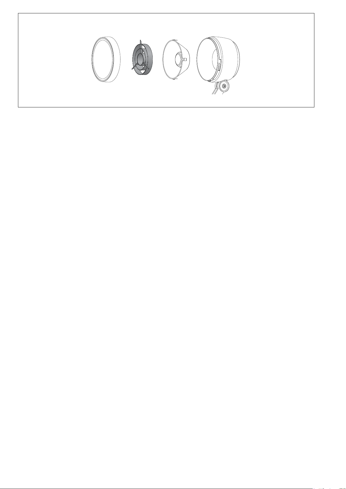
Bodeneinbauscheinwerfer 84 789 · 84 800
Senkschrauben lösen.
Abdeckring und Glas mit Dichtung abheben.
Zum Einbau des Rasters die Verstelleinrichtung
aus dem Leuchtengehäuse entnehmen.
Hierzu einen kleinen Schraubendreher in
die seitliche Öffnung der schwarzen Ronde
führen und die Verstelleinrichtung vorsichtig
heraushebeln.
Steckerteil der LED-Anschlussleitung am
Netzteil abziehen.
Innensechskantschraube (SW3) in der
schwarzen Ronde lösen und das Kugelgehäuse
entnehmen.
Zum Öffnen des Kugelgehäuses die drei
Zylinderschrauben (TorxantriebT10) lösen und
Glashaltering mit Glas und Dichtung abheben.
Raster so auf das Glas auegen, dass die drei
außenliegenden Stege des Rasters in den drei
Aussparungen der Glasdichtung liegen (siehe
Skizze Abb.B).
Kugelgehäuse auf den Glashaltering aufsetzen
und Zylinderschrauben gleichmäßig fest
anziehen.
Die Montage erfolgt in umgekehrter
Reihenfolge.
Steckerteil der LED-Anschlussleitung am
Netzteil einstecken.
Verstelleinrichtung in das Leuchtengehäuse
einsetzen und andrücken.
Innensechskantschraube lösen und
Neigungswinkel und Ausstrahlrichtung
der LED einstellen. Innensechskantschraube
anziehen.
In-ground oodlights 84 789 · 84 800
Loosen the countersunk screws.
Lift out the trim ring and glass with gasket.
To install the louvre, remove the internal
adjusting device from the luminaire housing.
Insert a small screwdriver into the opening on
the side of the black round blank and carefully
lever out the adjusting device.
Disconnect the plug part of the LED connecting
cable on the power supply unit.
Unscrew the hexagon socket screw (wrench
size3mm) inside the black round blank and
remove the ball housing.
To open the ball housing, loosen the three
cylinder screws (Torx driverT10) and lift off the
lens retaining ring together with the lens and
gasket.
Place the louvre on the lens so that the three
outer stays of the louvre t into the three
recesses of the glass gasket (see diagram
Fig.B).
Position the ball housing on the lens retaining
ring and tighten the cylinder screws evenly.
Install in reverse order.
Connect the plug part of the LED connecting
cable on the power supply unit.
Insert the adjusting device into the luminaire
housing and press it down.
Undo hexagon socket screw and adjust tilt
angle and beam direction of the LED.
Tighten hexagon socket screw.
Projecteurs encastrés dans le sol
84 789 · 84 800
Desserrer les vis à tête fraisée.
Soulever l’anneau de nition et le verre avec le
joint.
Pour encastrer la grille, retirer le dispositif de
réglage du boîtier du luminaire.
Pour ce faire, passer un petit tournevis dans
l’ouverture latérale de la rondelle noire et
extraire avec précaution le dispositif de réglage.
Sur le bloc d’alimentation, retirer la che du
câble de raccordement LED.
Desserrer la vis à six pans creux (SW3) dans la
rondelle noire et retirer le boîtier sphérique.
Pour ouvrir le boîtier sphérique, desserrer les
trois vis cylindriques (couple de serrageT10) et
soulever l’anneau de retenue du verre avec le
verre et le joint.
Placer la grille sur le verre de sorte que les trois
tiges extérieures de la grille se trouvent dans les
trois évidements du joint du verre (voir schéma
g.B).
Placer le boîtier sphérique sur l’anneau de
retenue du verre et serrer fermement et
régulièrement les vis cylindrique.
Pour l’installation, suivre les étapes en sens
inverse.
Brancher la che du câble de raccordement
LED au bloc d’alimentation.
Insérer le dispositif de réglage dans le boîtier du
luminaire et appuyer.
Desserrer le vis à six pans creux. Régler l’angle
d’inclinaison et orienter la direction de diffusion
du LED. Serrer le vis à six pans creux.
Glas mit Dichtung mit der abgestuften Seite
nach oben in das Leuchtengehäuse einlegen.
Auf richtigen Sitz der Dichtung achten.
Abdeckring auf Glasstufe aufsetzen und
Schrauben über Kreuz gleichmäßig fest
anziehen.
Anzugsdrehmoment = 5 Nm.
Place glass with gasket with stepped side
upturned into the luminaire housing.
Make sure that gasket is positioned correctly.
Place cover ring onto the glass step and tighten
screws crosswise.
Torque = 5 Nm.
Installer le verre avec le joint avec l’épaulement
du verre positionné vers le haut sur le boîtier du
luminaire. Veiller au bon emplacement du joint.
Poser l’anneau de fermeture sur l’épaulement
du verre et serrer en croix et fermement les vis.
Moment de serrage = 5 Nm.

BEGA Gantenbrink-Leuchten KG · Postfach 31 60 · 58689 Menden · info@bega.com · www.bega.com
4/4
A B
123
4
Bodeneinbauscheinwerfer 84 899
Senkschrauben lösen und Edelstahlring
abheben.
Glas und Dichtung herausnehmen.
Innensechskantschrauben (SW3) lösen und
den Klemmring entnehmen.
Das Kugelgehäuse anheben und den
Verriegelungsstift (Innensechskant SW2,5) auf
der Rückseite lösen. Glashaltering mit Glas und
Dichtung durch Linksdrehung abnehmen.
Den Dichtring zwischen Glas und Reektor
entfernen.
Raster in den Reektor einsetzen. Glas auf dem
Raster positionieren und den Glashaltering so
auf dem Kugelgehäuse aufsetzen, dass die
Kerben im Glashaltering und Kugelgehäuse
übereinander liegen.
Glahaltering rechtsherum bis zum Anschlag
aufdrehen. Verriegelungsstift einschrauben.
LED-Anschlussleitung vom Kugelgehäuse in
das Einbaugehäuse zurückführen.
Klemmring einlegen, beide
Innensechskantschrauben leicht anziehen und
Einstellung der Ausstrahlrichtung vornehmen.
Innensechskantschrauben gleichmäßig fest
anziehen.
Glasdichtung mit der breiten Seite nach oben
um das Glas legen. Glas (abgestufte Seite nach
oben) in das Leuchtengehäuse einsetzen und
fest eindrücken. Dabei auf den richtigen Sitz
der Dichtung achten.
Edelstahlring auf Glasstufe und Kunststoffring
auegen und die Schrauben über Kreuz
gleichmäßig fest anziehen.
Anzugsdrehmoment = 6,5 Nm.
In-ground oodlights 84 899
Remove the countersunk screws and lift out
the stainless steel ring.
Remove the glass and the gaskets.
Unscrew the hexagon socket screws (wrench
size3mm) and remove the clamping ring.
Lift the ball housing and unscrew the
locking pin (hexagon socket screw wrench
size2.5mm) on the back. Remove the glass
retaining ring along with the glass and gasket
by twisting it anti-clockwise.
Remove the gasket ring between the glass and
reector.
Insert the louvre into the reector. Position
the glass on the louvre and place the glass
retaining ring on the ball housing in such a way
that the notches in the glass retaining ring and
ball housing sit on top of one other.
Twist on the glass retaining ring clockwise as
far as the stop. Screw in the locking pin.
Guide the LED connecting cable from the ball
housing back into the installation housing.
Insert the clamping ring, slightly tighten both
hexagon socket screws and adjust the beam
direction.
Tighten the hexagon socket screws evenly.
Place the glass gasket around the glass with
the wider side facing up. Insert the glass (with
the stepped side facing up) into the luminaire
housing and press down hard. Make sure the
gasket is properly positioned.
Place the stainless-steel ring onto the glass
step and ring made of synthetic material, and
tighten the screws rmly crosswise.
Torque = 6.5 Nm.
Projecteurs encastrés dans le sol 84 899
Desserrer les vis à tête fraisée et retirer l’anneau
en acier inoxydable.
Retirer le verre et le joint.
Desserrer les vis à six pans creux (SW3) et
retirer l’anneau de blocage.
Soulever le boîtier sphérique et desserrer la
goupille de verrouillage (hexagonale SW2,5)
sur l’arrière. Retirer l’anneau de retenue du
verre avec le verre et le joint en tournant vers la
gauche.
Retirer le joint entre le verre et le réecteur.
Insérer la grille dans le réecteur. Positionner le
verre sur la grille et placer l’anneau de retenue
du verre sur le boîtier sphérique de sorte que
les encoches de l’anneau de retenue du verre
et du boîtier sphérique se superposent.
Fixer l’anneau de retenue du verre en le
tournant vers la droite jusqu’en butée. Visser la
goupille de verrouillage.
Faire passer le câble de raccordement
LED du boîtier sphérique dans le boîtier
d’encastrement.
Insérer l’anneau de blocage, serrer légèrement
les deux vis à six pans creux et procéder au
réglage de l’orientation du faisceau.
Serrer fort et uniformément les vis à sixpans
creux.
Placer le joint du verre autour du verre, avec le
côté le plus large vers le haut. Placer le verre
dans le boîtier du luminaire (côté étagé vers
le haut) et presser fermement. Veiller au bon
emplacement du joint.
Positionner l’anneau en acier inoxydable sur le
rebord étagé du verre et l’anneau en matière
synthétique, et serrer fort et uniformément les
vis en croix.
Moment de serrage = 6,5 Nm.
This manual suits for next models
5
Other BEGA Floodlight manuals