manuals.online logo
Brands
  1. Home
  2. •
  3. Brands
  4. •
  5. BEGA
  6. •
  7. Floodlight
  8. •
  9. BEGA 84 534 User manual

BEGA 84 534 User manual

BEGA Gantenbrink-Leuchten KG · Postfach 31 60 · 58689 Menden · info@bega.com · www.bega.com
11.17 · Technische Änderungen vorbehalten · Technical amendments reserved · Modications techniques réservées
IP 65
!
Flächenscheinwerfer RGBW · ZigBee
Surface oodlight RGBW · ZigBee
Projecteur extensif RGBW · ZigBee
84 534
125125290290
165165100100
4040
192192
270270
25
67
Ø 4,5
Gebrauchsanweisung Instructions for use Fiche d’utilisation
Anwendung
LED-Flächenscheinwerfer mit Montagedose für
additive Farbmischung RGBW.
Der Scheinwerfer kann über eine ZigBee-
Farblichtsteuerung (Color Control) gesteuert
werden. Dazu empfehlen wir unsere Steuerung
BEGA Control.
Application
LED Surface oodlight with mounting box for
additive colour mixing RGBW.
The oodlight can be controlled by ZigBee
colour light control (Color Control).
We recommend our BEGA Control system for
this purpose.
Utilisation
Projecteur extensif à LED avec boîte de
montage pour mixage de couleurs RGBW.
Le projecteur peut être commandé via un
système de contrôle de couleurs ZigBee (Color
Control). Nous recommandons d’utiliser le
système BEGA Control.
Leuchtmittel
Modul-Anschlussleistung 39,5W
Leuchten-Anschlussleistung 46W
Bemessungstemperatur ta=25 °C
Umgebungstemperatur ta max =40 °C
Modul-Bezeichnung LED-0555/RGBW
Leuchtenlichtstrom 2824lm
Leuchten-Lichtausbeute 61,4 lm / W
Lamp
Module connected wattage 39.5W
Luminaire connected wattage 46W
Rated temperature ta=25 °C
Ambient temperature ta max =40 °C
Module designation LED-0555/RGBW
Luminaire luminous ux 2824lm
Luminaire luminous efciency 61,4 lm / W
Lampe
Puissance raccordée du module 39,5W
Puissance raccordée du luminaire 46W
Température de référence ta=25 °C
Température d’ambiance ta max = 40 °C
Marquage des modules LED-0555/RGBW
Flux lumineux du luminaire 2824lm
Rendement lum. d’un luminaire 61,4 lm / W
Produktbeschreibung
Leuchte besteht aus Aluminiumguss,
Aluminium und Edelstahl
Sicherheitsglas mit optischer Struktur
Silikondichtung
Reektor aus eloxiertem Reinstaluminium
Drehbereich des Scheinwerfers 350°
Schwenkbereich -35°/+70°
Montagedose mit 2 Befestigungsbohrungen
ø 4,5 mm · Abstand 67 mm
2 Leitungseinführungen zur Durchverdrahtung
der Anschlussleitung ø 7-10,5 mm,
max. 5G 1,5@
Anschlussklemme 2,5@
mit Steckvorrichtung
Schutzleiteranschluss
mit eingebautem ZigBee-Funkmodul
Leistungspegel: +8 dBm
Funkfrequenz 2,4 GHz
Kann als Router oder Koordinator in
ZigBee-Netzwerken eingesetzt werden
Home Automation Prole 1.2.1
LED-Netzteil
220-240V x 0/50-60Hz
Schutzklasse I
Schutzart IP 65
Staubdicht und Schutz gegen Strahlwasser
Schlagfestigkeit IK07
Schutz gegen mechanische
Schläge < 2 Joule
c – Konformitätszeichen
Gewicht: 4,0 kg
Product description
Luminaire made of aluminium alloy, aluminium
and stainless steel
Safety glass with optical structure
Silicone gasket
Reector made of pure anodised aluminium
Rotation range of oodlight 350°
Swivel range -35°/+70°
Mounting box with 2 xing holes
ø 4.5 mm · 67 mm spacing
2 cable entries for through-wiring of mains
supply cable ø 7-10,5 mm,
max. 5G 1.5@
Connecting terminal 2.5@
with plug connection
Earth conductor connection
with integral ZigBee radio module.
Power level: +8 dBm
Radio frequency 2.4GHz
Can be used as a router or coordinator in
ZigBee networks
Home Automation Prole 1.2.1
LED power supply unit
220-240V x 0/50-60Hz
Safety class I
Protection class IP 65
Dust-tight and protection against water jets
Impact strength IK07
Protection against mechanical
impacts < 2 joule
c – Conformity mark
Weight: 4.0 kg
Description du produit
Luminaire fabriqué en fonderie d'aluminium,
aluminium et acier inoxydable
Verre de sécurité à structure optique
Joint silicone
Réecteur en aluminium pur anodisé
Projecteur orientable sur 350°
Inclinaison -35°/+70°
Boîte de montage avec 2 trous de xation
ø 4,5 mm · Entraxe 67 mm
2 entrées de câble pour branchement en
dérivation d’un câble de raccordement
ø 7-10,5 mm, max. 5G 1,5@
Bornier 2,5@
avec connecteur embrochable
Raccordement de mise à la terre
Avec module radio ZigBee intégré
Niveau de puissance: +8dBm
Fréquence radio 2,4 GHz
Peut être utilisé comme routeur ou coordinateur
dans
les réseaux ZigBee
Home Automation Prole 1.2.1
Bloc d'alimentation LED
220-240V x 0/50-60Hz
Classe de protection I
Degré de protection IP 65
Etanche à la poussière et protégé contre les
jets d’eau
Résistance aux chocs mécaniques IK07
Protection contre les chocs
mécaniques < 2 joules
c – Sigle de conformité
Poids: 4,0 kg
BEGA Gantenbrink-Leuchten KG · Postfach 31 60 · 58689 Menden · info@bega.com · www.bega.com
Lichttechnik
Breitstreuende Lichtstärkeverteilung.
Halbstreuwinkel 81/84°.
Leuchtendaten für das Lichttechnische
Berechnungsprogramm DIALux für
Außenbeleuchtung, Straßenbeleuchtung und
Innenbeleuchtung, sowie Leuchtendaten im
EULUMDAT und im IES-Format nden Sie auf
der BEGA Internetseite www.bega.de.
Light technique
Broad spread light distribution.
Half beam angle 81/84°.
Luminaire data for the light planning program
DIALux for outdoor lighting, street lighting and
interior lighting as well as luminaire data in
EULUMDAT and IES format are available on the
BEGA website www.bega.com.
Technique d’éclairage
Répartition lumineuse extensive.
Angle de diffusion à demi-intensité 81/84°.
Les données des luminaires pour le programme
de calcul d’éclairage DIALux concernant
l’éclairage extérieur, l’éclairage des rues et
l’éclairage intérieur, de même que les données
des luminaires aux formats EULUMDAT et IES
gurent sur notre site BEGA www.bega.com.
Sicherheit
Für die Installation und für den Betrieb
dieser Leuchte sind die nationalen
Sicherheitsvorschriften zu beachten.
Der Hersteller übernimmt keine Haftung für
Schäden, die durch unsachgemäßen Einsatz
oder Montage entstehen.
Werden nachträglich Änderungen an der
Leuchte vorgenommen, so gilt derjenige als
Hersteller, der diese Änderungen vornimmt.
Safety indices
The installation and operation of this luminaire
are subject to national safety regulations.
The manufacturer is then discharged from
liability when damage is caused by improper
use or installation.
If any luminaire is subsequently modied, the
persons responsible for the modication shall
be considered as manufacturer.
Sécurité
Pour l’installation et l’utilisation de ce luminaire,
respecter les normes de sécurité nationales.
Le fabricant décline toute responsabilité
résultant d'une mise en œuvre ou d'une
installation inappropriée du produit.
Toutes les modications apportées au luminaire
se feront sous la responsabilité exclusive de
celui qui les effectuera.
BEGA 611178
Commissioning Mode:
S=BEGA HS Mode
T=ZigBee Home Automation Mode
Device Role:
C=Coordinator
R=Router
Uin= 24 V/48 V DC
tc=85°C
R/C
T/S
T1
LED 1
LED 2
T2
tc
LED 1
LED 2
T2
T1
DIP 2
DIP 1
R
T
C
S
Montage
Anlage spannungsfrei schalten.
Der Scheinwerfer ist im Auslieferungszustand
als Router konguriert und tritt einem
bestehenden Netzwerk, sobald es geöffnet und
der Scheinwerfer an die Versorgungsspannung
angeschlossen wird, automatisch bei.
Um den Scheinwerfer als Koordinator ein
Netzwerk eröffnen zu lassen, muss im
Scheinwerfergehäuse der DIP-Schalter 1
am Steuermodul von "R" auf "C" geschaltet
werden.
Dazu Innensechskantschrauben (SW 4) lösen.
Abdeckrahmen mit Sicherheitsglas, Dichtung
und Reektor vorsichtig abnehmen und die
Antennenleitung abziehen.
Innensechskantschrauben (SW 4) hinter
dem Reektor lösen und Gehäuseunterteil
abnehmen.
Einstellung vornehmen.
Installation
Disconnect the electrical installation.
The oodlight is congured as a router by
default and will automatically join an existing
network as soon as the network is opened
and the oodlight is connected to the supply
voltage.
To enable the oodlight to open a network as
coordinator, DIP switch 1 on the control module
in the oodlight housing must be switched from
"R" to "C".
This requires you to undo the hexagon socket
screws (SW4).
Carefully remove the cover frame together with
the safety glass, gasket and reector, and pull
off the aerial cable.
Undo the hexagon socket screws (SW 4)
behind the reector and remove the bottom
part of the housing.
Make adjustment.
Installation
Débrancher l’alimentation.
À la livraison, le projecteur est conguré comme
un routeur et s'intègre automatiquement
au réseau existant dès son ouverture et sa
connexion à la tension d'alimentation.
Pour permettre au projecteur d'ouvrir un
réseau en tant que coordinateur, le module de
contrôle de l'interrupteur DIP 1 doit être réglé
sur «C», et non plus sur «R», dans le corps
de projecteur.
Pour ce faire, il faut desserrer la vis à six pans
creux SW 4.
Retirer le cadre de nition et son verre de
sécurité, le joint d'étanchéité et le réecteur
avec précaution et tirer sur le câble de
l'antenne.
Desserrer la vis à six pans creux (SW 4) derrière
le réecteur et retirer la partie inférieure du
projecteur.
Procéder au réglage.
Bitte beachten Sie:
Den im Leuchtengehäuse bendlichen
Trockenmittelbeutel nicht entfernen.
Er dient zur Aufnahme von Restfeuchtigkeit.
Please note:
Do not remove the desiccant pouch from the
luminaire housing.
It is needed to remove residual moisture.
Attention:
Ne pas ôter le sachet de dessicant se trouvant
dans l'armature.
Il permet d'absorber l'humidité résiduelle.
Gehäuseunterteil montieren.
Abdeckrahmen aufsetzen und Schrauben
über Kreuz gleichmäßig anziehen.
Fit the bottom part of the housing.
Fit the cover frame and tighten the screws
uniformly in crosswise fashion.
Installer la partie inférieure du projecteur.
Placer le cadre de nition et serrer
uniformément et
en croix les vis.
~ 1 x
BEGA Gantenbrink-Leuchten KG · Postfach 31 60 · 58689 Menden · info@bega.com · www.bega.com
Schraube an der Montagedose bis zum
Anschlag lösen. Montageplatte rechtsherum bis
zum Anschlag drehen und entnehmen.
Anschlussleitung durch die Leitungs-
einführung der Montageplatte führen.
Montageplatte mit beiliegendem oder
anderem geeigneten Befestigungsmaterial
auf Montagegrund befestigen.
Dabei unbedingt beiliegende Dichtringe
verwenden.
Undo the screw at the mounting box as far as it
will go. Turn mounting plate clockwise as far as
it will go and remove it.
Lead the connecting cable through the
cable entry of the mounting plate.
Fix the mounting plate with enclosed or
any other suitable xing material onto the
mounting surface.
Be sure to use the gasket rings supplied.
Desserrer la vis de la boîte de montage jusqu'à
la butée et retirer la contre-plaque de la platine
en tournant vers la droite jusqu' à la butée.
Introduire le câble d’alimentation à travers
l'entrée de câble de la contre-plaque.
Fixer la contre-plaque sur le support
de montage avec le matériel de xation
fourni ou tout autre matériel approprié.
Utiliser impérativement les joints fournis.
Schutzleiterverbindung herstellen und
elektrischen Anschluss vornehmen.
Steckerteil in Steckvorrichtung bis zum
Anschlag eindrücken.
Auf richtigen Sitz der Dichtung achten.
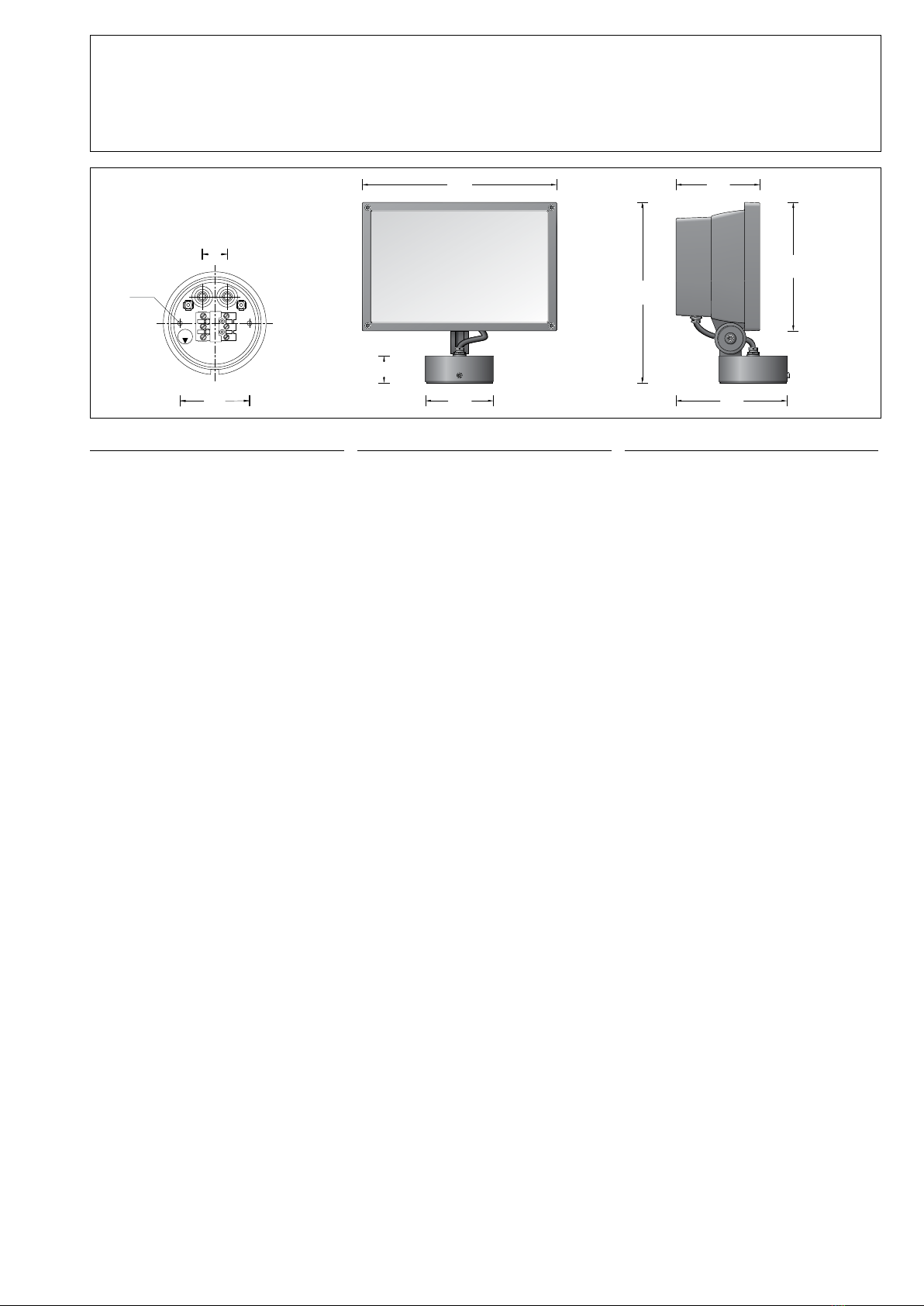
Scheinwerfer – wie in Skizze dargestellt –
auf die Montageplatte setzen, ausrichten und
fest verschrauben.
Scheinwerfereinstellung vornehmen.
Gelenkschraube lösen und Scheinwerfer
einstellen. Gelenkschraube anziehen.
Anzugsdrehmoment 7 Nm.
Make the earth conductor connection and
the electrical connection.
Push plug into coupler as far as it will go.
Make sure that gasket is positioned correctly.
Place oodlight unit onto the mounting plate
– as displayed in the sketch – align and screw
together rmly.
Adjust oodlight.
Torque of the joint screw 7 Nm.
Mettre à la terre et procéder au
raccordement électrique.
Enfoncer la che dans le connecteur
embrochable jusqu'à la butée.
Veiller au bon emplacement du joint.
Poser le projecteur – voir schéma – sur la
contre-plaque, ajuster et visser fermement.
Procéder au réglage du projecteur.
Desserrer la vis de la rotule et régler l'angle du
projecteur. Serrer fermement la vis de la rotule.
Moment de serrage 7 Nm.
Versorgungsspannung für die Module
einschalten.
Bei erstmaliger Inbetriebnahme wird das
Netzwerk automatisch für 180 s durch den
Koordinator geöffnet.
Alle Module die als Router eingestellt sind,
verbinden sich automatisch mit dem Netzwerk.
Funktionsverbindungen zwischen den Modulen
können jetzt hergestellt werden.
Switch on the supply voltage for the modules.
When starting up for the rst time, the network
will be opened automatically for 180 s by the
coordinator.
All the modules that are congured as routers
will connect automatically to the network.
Function-related connections can now be
created between the modules.
Mettre les modules sous tension.
À la première mise en service, le réseau s’ouvre
automatiquement pendant 180 s.
Tous les modules dénis comme routeurs se
connectent automatiquement au réseau.
Il est maintenant possible d’établir des liaisons
fonctionnelles entre les modules.
ZigBee-Netzwerkkonguration
Bei der Inbetriebnahme kann eine eindeutige
Zuordnung des Scheinwerfers über die
Seriennummer erfolgen, die auf dem Modul
verklebt wurde.
Für die bauseitige Dokumentation können die
drei beiliegenden Seriennummern-Etiketten
verwendet werden.
Ein Modul im Netzwerk als Koordinator
bestimmen und DIP-Schalter 1 (R/C: Router /
Koordinator) auf "C" stellen.
Alle weiteren Module im Netzwerk bleiben
Router und der DIP-Schalter 1 (R/C) wird auf
"R" gestellt.
Bei BEGA ZigBee-Komponenten ist dies die
Standardeinstellung.
Sicherheitsmodus für die Datenkommunikation
durch den DIP-Schalter 2 (T/S: Tastermodus /
Sicherheitsmodus) bestimmen.
Bei Verwendung des hohen Sicherheitsmodus
den DIP-Schalter 2 auf "S" stellen, dieser
Modus ist jedoch nur in Verbindung mit der
ZigBee Programmiersoftware 70 011 möglich.
Die ZigBee Programmiersoftware 70 011
ermöglicht das einfache und komfortable
Programmieren und Parametrieren einer ZigBee
Anlage.
Das Netzwerk kann am Koordinator oder
Router durch kurzes gleichzeitiges Drücken
der Funktionstaster (T1 und T2) geöffnet bzw.
geschlossen werden.
ZigBee network conguration
When starting up for the rst time, the oodlight
can be identied by the serial number stuck to
the module.
For documentation on site, the three enclosed
serial number labels can be used.
Dene one module in the network as the
coordinator and set DIP switch1 (R/C: Router /
Coordinator) to "C".
All other modules in the network will remain
routers, and DIP switch1 (R/C) will be set to
"R".
This is the standard setting on BEGA ZigBee
components.
Dene safety mode for data communication via
DIP switch2 (T/S: Pushbutton Mode / Safety
Mode).
When using the high safety mode, set DIP
switch 2 to "S"; however, this mode is only
possible in conjunction with
ZigBee programming software 70 011.
ZigBee programming software 70 011 is an
easy and user-friendly solution for programming
and parameterising a ZigBee system.
The network can be opened and closed at
the coordinator or router by pressing briey
on both function pushbuttons (T1 and T2)
simultaneously.
Conguration de réseau ZigBee
Lors de la mise en service, il est possible de
procéder à l'affectation unique du projecteur
grâce au numéro de série qui a été collé sur le
module.
Les trois étiquettes jointes comportant les
numéros de série peuvent être utilisées pour la
documentation sur site.
Dénir un module dans le réseau comme
coordinateur et placer l'interrupteur DIP 1
(R/C: Routeur / Coordinateur) sur «C».
Tous les autres modules du réseau restent des
routeurs et l'interrupteur DIP 1 (R/C) est réglé
sur «R».
Cela correspond au réglage standard des
composants BEGA ZigBee.
Dénir le mode de sécurité pour la
communication des données par l'interrupteur
DIP 2 (T/S: Mode bouton-poussoir / mode de
sécurité).
Si le mode de sécurité élevé est utilisé, placer
l’interrupteur DIP 2 sur «S». Ce mode n’est
cependant possible qu’avec le
logiciel de programmation ZigBee 70 011.
Le logiciel de programmation ZigBee 70 011
permet de programmer et de paramétrer
aisément une installation ZigBee.
Pour ouvrir ou fermer le réseau au niveau
du coordinateur ou du routeur, appuyer
simultanément et brièvement sur les touches
de fonction (T1 et T2).
Reinigung · Pege
Leuchte regelmäßig mit lösungsmittelfreien
Reinigungsmitteln von Schmutz und
Ablagerungen säubern.
Dafür keinen Hochdruckreiniger verwenden.
Cleaning · Maintenance
Clean luminaire regularly with solvent-free
cleansers from dirt and deposits.
Do not use high pressure cleaners.
Nettoyage · Entretien
Nettoyer régulièrement le luminaire et le
débarrasser des dépôts et des souillures.
Ne pas utiliser de nettoyeur haute pression.
Wartung
Die Verbindungsleitung ist zwischen
Montagedose und Scheinwerfer auf äußere
Beschädigungen zu prüfen und darf nur durch
eine Elektro-Fachkraft ersetzt werden.
Maintenance
The connecting cable between mounting box
and oodlight has to be inspected regarding
obvious damages and has to be replaced by a
qualied electrician only.
Entretien
Vérier l’état du câble de raccordement entre la
boîte de montage et le projecteur. Le câble ne
doit être remplacé que par un électricien agréé.
BEGA Gantenbrink-Leuchten KG · Postfach 31 60 · 58689 Menden · info@bega.com · www.bega.com
Austausch des LED-Moduls
Die Bezeichnung des LED-Moduls ist auf einem
Etikett in der Leuchte vermerkt.
BEGA Ersatzmodule entsprechen in Lichtfarbe
und Lichtleistung den ursprünglich verbauten
Modulen.
Der Austausch kann mit handelsüblichem
Werkzeug durch qualizierte Personen erfolgen.
Anlage spannungsfrei schalten und Leuchte
öffnen.
Bitte beachten Sie die Montageanleitung des
LED-Moduls.
Dichtungen der Leuchte überprüfen, ggf.
ersetzen.
Ein defektes Glas muss ersetzt werden.
Leuchte schließen.
Replacing the LED module
The designation of the LED module is noted on
a label in the luminaire.
The light colour and light output of BEGA
replacement modules correspond to those of
the modules originally tted.
The module can be replaced by qualied
persons using standard tools.
Disconnect the system and open the luminaire.
Please follow the installation instructions for the
LED module.
Inspect and, if necessary, replace the luminaire
gaskets.
Defective glass must be replaced.
Close the luminaire.
Remplacement du module LED
La désignation du module LED est inscrite sur
une étiquette apposée sur le luminaire.
Les modules de rechange BEGA
correspondent aux modules d’origine en
termes de couleur de lumière et de ux
lumineux. Le module LED peut être remplacé
par une personne qualiée à l’aide d’outils
disponibles dans le commerce.
Travailler hors tension et ouvrir le luminaire.
Respecter la che d’utilisation du module LED.
Vérier et remplacer les joints du luminaire le
cas échéant.
Un verre endommagé doit être remplacé.
Fermer le luminaire.
Ergänzungsteile
70 525 Blende
Die aufsetzbare Blende schirmt die
Lichtaustrittsöffnung nach oben oder unten ab.
Accessories
70 525 Shield
The attachable shield screens the light upwards
or downwards.
Accessoires
70 525 Visière
La visière amovible masque la lumière vers le
haut ou vers le bas.
Es gibt dazu eine gesonderte
Gebrauchsanweisung. A separate instructions for use can be provided
upon request. Une che d’utilisation pour ces accessoires est
disponible.
Ersatzteile
Ersatzglas 141099
LED-Netzteil DEV-0178/24V
Dimmbox 611108
ZigBee-Funkmodul 611178
LED-Modul LED-0555/RGBW
Reektor 761402.1
Dichtung Montagedose 830679
Dichtung Glas 831498
Dichtung Gehäuse 831508
Spares
Spare glass 141099
LED power supply unit DEV-0178/24V
Dimming box 611108
ZigBee radio module 611178
LED module LED-0555/RGBW
Reector 761402.1
Gasket mounting box 830679
Gasket glass 831498
Gasket housing 831508
Pièces de rechange
Verre de rechange 141099
Bloc d’alimentation LED DEV-0178/24V
Dimmer 611108
Module radio ZigBee 611178
Module LED LED-0555/RGBW
Réecteur 761402.1
Joint boîte de montage 830679
Joint du verre 831498
Joint du boîtier 831508

Other BEGA Floodlight manuals

BEGA 77 629 User manual

BEGA

BEGA 77 629 User manual

BEGA 84 361 User manual

BEGA

BEGA 84 361 User manual

BEGA 84 293 User manual

BEGA

BEGA 84 293 User manual

BEGA 84 292K3 User manual

BEGA

BEGA 84 292K3 User manual

BEGA 84 860 User manual

BEGA

BEGA 84 860 User manual

BEGA 77 702 Manual

BEGA

BEGA 77 702 Manual

BEGA 7542 User manual

BEGA

BEGA 7542 User manual

BEGA 84 525 User manual

BEGA

BEGA 84 525 User manual

BEGA 10 200 User manual

BEGA

BEGA 10 200 User manual

BEGA 7516 User manual

BEGA

BEGA 7516 User manual

BEGA 84 519 User manual

BEGA

BEGA 84 519 User manual

BEGA 84 533 User manual

BEGA

BEGA 84 533 User manual

BEGA Gobo 84 977 User manual

BEGA

BEGA Gobo 84 977 User manual

BEGA 84 812 User manual

BEGA

BEGA 84 812 User manual

BEGA 9475 User manual

BEGA

BEGA 9475 User manual

BEGA 84 975 User manual

BEGA

BEGA 84 975 User manual

BEGA 7101 User manual

BEGA

BEGA 7101 User manual

BEGA 84 524 Manual

BEGA

BEGA 84 524 Manual

BEGA 77 434 User manual

BEGA

BEGA 77 434 User manual

BEGA 84 378 User manual

BEGA

BEGA 84 378 User manual

BEGA 84 299 K3 User manual

BEGA

BEGA 84 299 K3 User manual

BEGA 84 978 User manual

BEGA

BEGA 84 978 User manual

BEGA 84 234 User manual

BEGA

BEGA 84 234 User manual

BEGA 8208 User manual

BEGA

BEGA 8208 User manual

Popular Floodlight manuals by other brands

Larson Electronics LEDWP-720 manual

Larson Electronics

Larson Electronics LEDWP-720 manual

LIGHTSIDE LZS 1000 user manual

LIGHTSIDE

LIGHTSIDE LZS 1000 user manual

ACR Electronics RCL-100 Trouble shooting and parts replacement manual

ACR Electronics

ACR Electronics RCL-100 Trouble shooting and parts replacement manual

Beamz LCB288 user manual

Beamz

Beamz LCB288 user manual

LIGMAN PITTSBURGH 3 installation manual

LIGMAN

LIGMAN PITTSBURGH 3 installation manual

YPHIX 50508234 installation manual

YPHIX

YPHIX 50508234 installation manual

Boeing SPECTROLAB SX-16 Nightsun Maintenance manual

Boeing

Boeing SPECTROLAB SX-16 Nightsun Maintenance manual

EuroLite LED Theatre COB 200 CW user manual

EuroLite

EuroLite LED Theatre COB 200 CW user manual

NORDRIDE LOOP POWER operating instructions

NORDRIDE

NORDRIDE LOOP POWER operating instructions

Show Tec Pixel bar 12 user guide

Show Tec

Show Tec Pixel bar 12 user guide

Heath Zenith SECUR360 9309 manual

Heath Zenith

Heath Zenith SECUR360 9309 manual

M-Elec NOX Series quick start guide

M-Elec

M-Elec NOX Series quick start guide

Claypaky ATLAS HMI 575W instruction manual

Claypaky

Claypaky ATLAS HMI 575W instruction manual

MegaLite 4070-N-E Color Punch user manual

MegaLite

MegaLite 4070-N-E Color Punch user manual

Timeguard LED100PIRBE Installation & operating instructions

Timeguard

Timeguard LED100PIRBE Installation & operating instructions

Night Watcher NW520 user guide

Night Watcher

Night Watcher NW520 user guide

Night Watcher NW720 user guide

Night Watcher

Night Watcher NW720 user guide

OR STEEL light ORPHIE Technical manual

OR STEEL light

OR STEEL light ORPHIE Technical manual

manuals.online logo
manuals.online logoBrands
  • About & Mission
  • Contact us
  • Privacy Policy
  • Terms and Conditions

Copyright 2025 Manuals.Online. All Rights Reserved.