Installation and Technical Information
BEGA
Due to the dynamic nature of lighting products and the associated technologies, luminaire data on this sheet is subject to change at the discretion of BEGA North America. For the most current technical data, please refer to bega-us.com
BEGA 1000 Bega Way, Carpinteria, CA 93013 (805)684-0533 © copyright BEGA 2023
Figure 2: 79 828 Anchorage Diagram
Figure 1: 79 828 Anchorage Details
Overview:
LED Watts: 22.5W
System Watts: 27.0W
Controllability: 0-10V dimmable to 1%
Weight: 52.9 lbs.
Protection Class: IP65
SEE PAGE 2
FOR DIRECT BURY INSTALLATION
Tools Required:
• 4mm Hex Key
• Special Access door tool (provided)
Notice to Installer:
1. See page 3 for specic product safety warnings.
2. 79 828 anchorage kit must be installed in concrete foundation.
[See Submittal for additional detail]
3. See page 2 for 71192 Anchorage Kit - Direct Bury Installation.
[See Submittal for additional detail]
4. Attention to alignment leveling, and location is required for proper installation.
5. The size of the foundation depends on the topography, condition of the soil and the
wind load needs to be determined by a structural engineer per-site.
Installation: 79 828 Anchorage Kit - Concrete
1. The protective coating pre-applied to the anchorage unit must not be damaged.
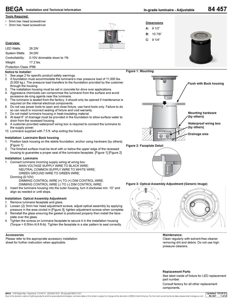
2. Anchor kit 79828 must be installed in concrete. This anchorage kit is buried below
the nished grade. [Figure 2]
3. Route conduit into the anchorage base. (Anchorage opening - 2 7/8” x 1 3/8”)
NOTE: Recommended to have minimum 5 ft. of excess wire to be able to
make connections at the hand hole.
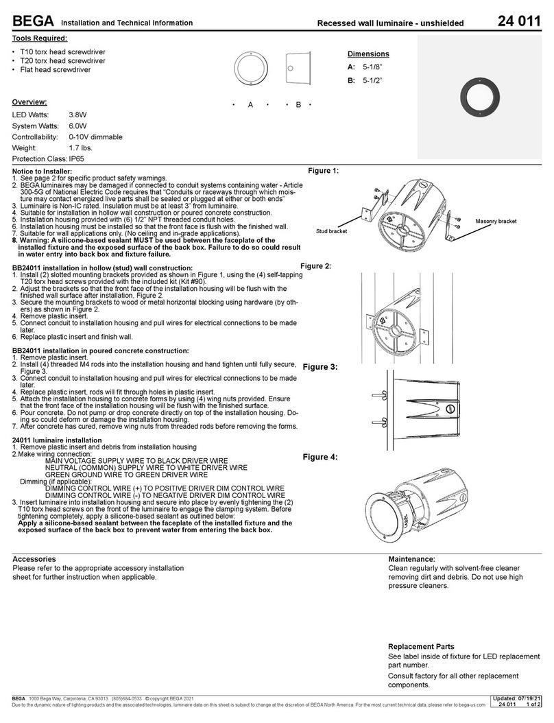
4. Consult with structural engineer to have footing designed to site specication.
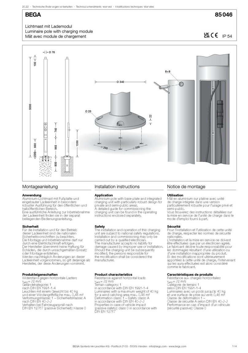
5. IMPORTANT: Align the anchor template (provided) with the desired luminaire
lighting output. See [Figure 1] to determine light output orientation.
6. Anchor bolts can be installed by either attaching template to concrete form, or by
inserting anchor bolts into poured concrete. Ensure template and anchor bolts are
leveled properly.
7. Attach anchor base to anchor bolts using leveling washers, lock washers, and hex
8. nuts (provided).
9. Finish grade and proceed to luminaire installation.
NOTE: Luminaire does not cover the entire height of the base and
mounts above the rectangular extrusion leaving approximately
5-1/4”tobelledwithnishgrade.[Figure2]
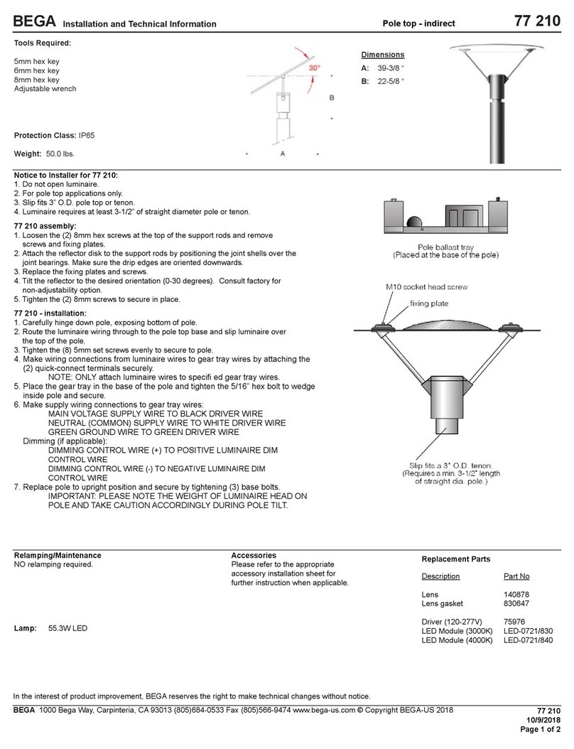
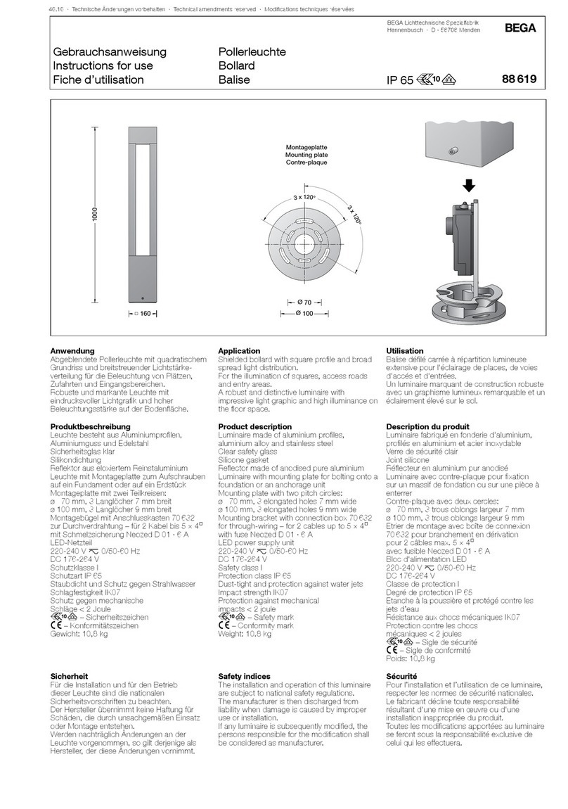
Installation: 84 563 Luminaire
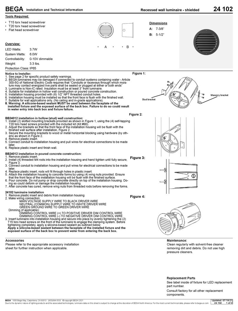
1. Unlock the fastener of the access door and remove the access door using special
tool (provided).
2. Undo 4mm hexagon socket head screws through the openings on base of luminaire.
3. Place luminaire onto anchorage.
4. Tighten hexagon socket screws rmly, Torque = 12 Nm, until screws are secure.
5. Pull supply wiring to access door opening and make supply wiring connections.
MAIN VOLTAGE SUPPLY WIRE TO BLACK WIRE.
NEUTRAL COMMON SUPPLY WIRE TO WHITE WIRE.
GREEN GROUND WIRE TO GREEN WIRE.
Dimming (0-10V):
DIMMING CONTROL WIRE (+) TO (+) [VIOLET] DIM CONTROL WIRE.
DIMMING CONTROL WIRE (-) TO (-) [PINK] DIM CONTROL WIRE.
6. Replace and lock the access door.
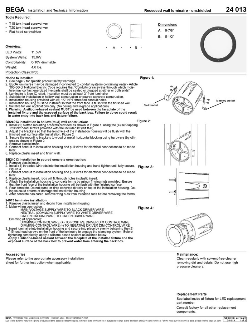
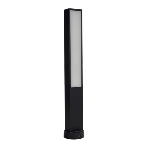
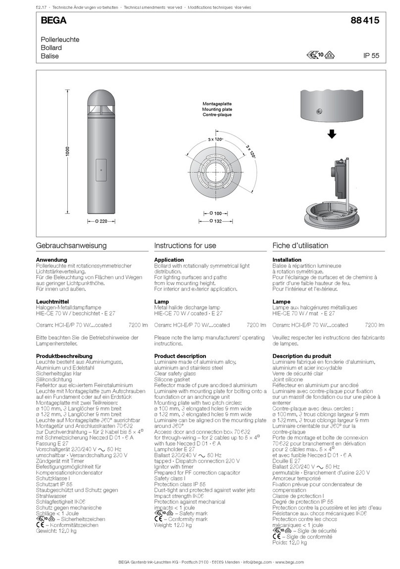
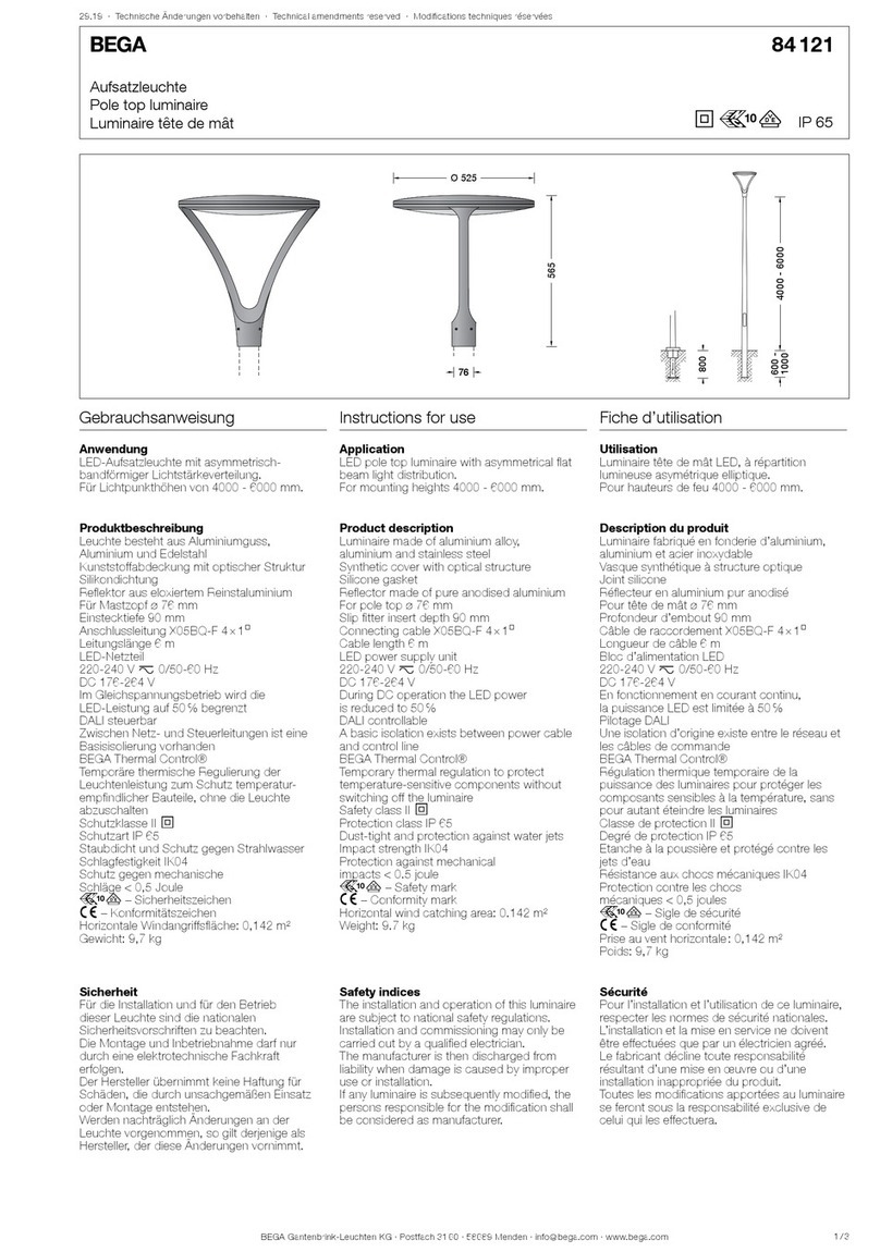
Building element - Light emission on one side 84 563
Dimensions
A: 4-3/4’’
B: 59-3/8’’
C: 138’’
Maintenance:
Clean regularly with solvent-free cleaner
removing dirt and debris. Do not use high
pressure cleaners.
Replacement Parts
See label inside of xture for LED replacement
part number.
Consult factory for all other replacement
components.
Accessories
Please refer to the appropriate accessory installation
sheet for further instruction when applicable.
Updated: 11/02/23
84 563 1 of 3


