manuals.online logo
Brands
  1. Home
  2. •
  3. Brands
  4. •
  5. Bpt
  6. •
  7. Intercom System
  8. •
  9. Bpt XPL/200 User manual

Bpt XPL/200 User manual

1
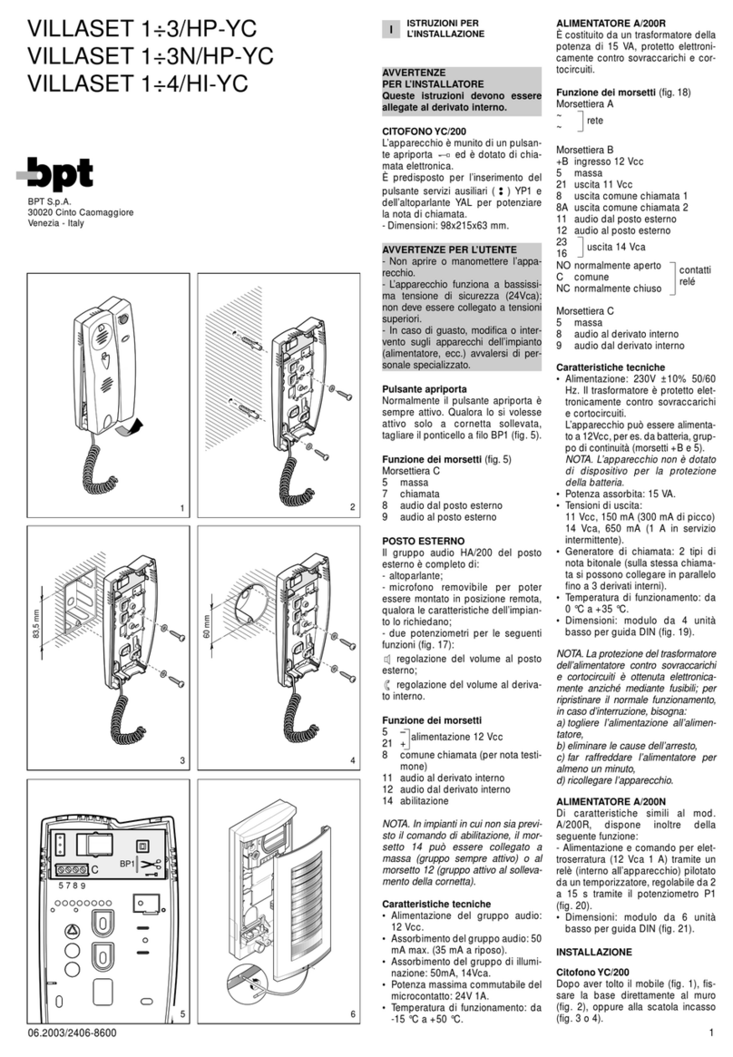
UNITÀ ATTENUATORE/INTER-
RUTTORE CON SEGNALAZIONE
LUMINOSA XPL/200
Da inserire nel citofono XC/200
(occupa lo spazio di due pulsanti).
Può essere utilizzato, ad esempio,
per attenuare o escludere la chia-
mata dal posto esterno.
Premere il pulsante, l’accensione
dell’indicazione luminosa rossa
conferma l’attenuazione o l’esclu-
sione di tale chiamata.
Funzioni del ponticello SW (fig.1)
SW inserito: funzionamento dell’u-
nità come attenuatore (default).
SW disinserito: funzionamento del-
l’unità come interruttore, per esclu-
dere la chiamata o altro servizio.
Funzione dei morsetti
5−alimentazione
21 +11÷17,5 Vcc
7
7A
Caratteristiche tecniche
•Alimentazione: 11÷17,5 Vcc.
•Assorbimento: 4 mA 11 Vcc - 7
mA 17,5 Vcc.
•Potere d’interruzione: 24 V 100
mA max.
•Temperatura di funzionamento:
da 0 °C a + 35 °C.
Installazione
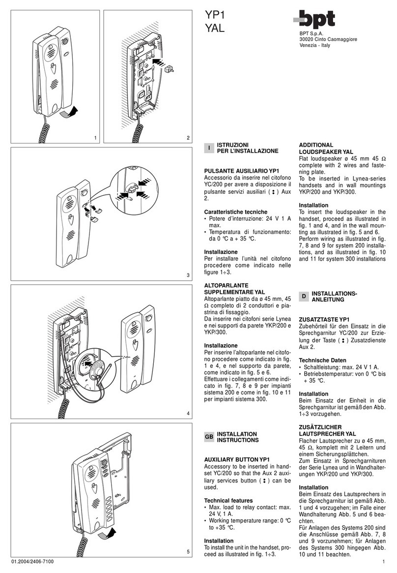
Installare l’unità nel citofono come
indicato nelle figure 1÷3.
Effettuare i collegamenti secondo
lo schema di fig. 4 oppure 5.
XPL/200
B.P.T. S.p.A.
30020 Cinto Caomaggiore
Venezia-Italy
SW
1
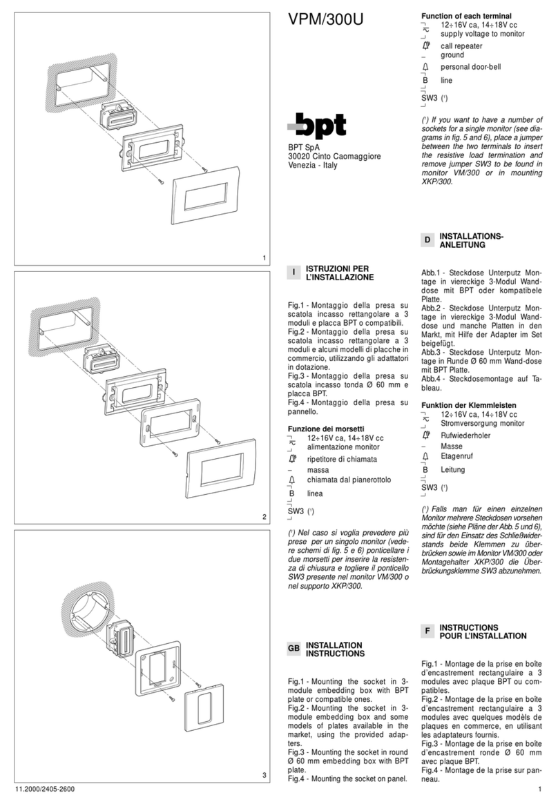
IISTRUZIONI
PER L’INSTALLAZIONE
GB INSTALLATION
INSTRUCTIONS
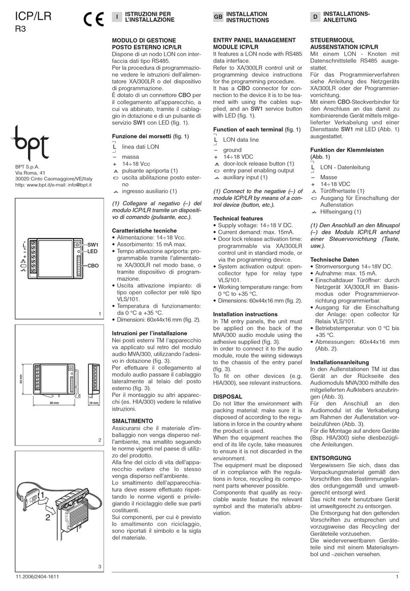
XPL/200 ATTENUATOR/SWITCH
UNIT WITH LAMP
For installation in handset XC/200
(uses the space of two buttons).
This switch can be used, for exam-
ple, to isolate the call from the
entry panel to the handset, or atte-
nuate it.
Press the button and the red indi-
cator comes on to indicate that the
call has been isolated or attenua-
ted.
Function of SW jumper (fig.1)
SW inserted: the unit works as an
attenuator (default).
SW disconnected: the unit works
as a switch, to disable the call or
other facility.
Function of each terminal
5−supply voltage
21 +11÷17,5 VDC
7
7A
Technical features
•Supply voltage: 11÷17,5 VDC.
•Current demand: 4 mA 11 VDC -
7 mA 17,5 VDC.
•Max load to contact: 24 V 100
mA max.
•Working temperature range: from
0 °C to + 35 °C.
Installation
Insert the unit in the handset as
shown in figures 1÷3.
Wire according to the diagram in
figure 4 or 5.
ABSCHWÄCHER/SCHALTEIN-
HEIT MIT LEUCHTANZEIGE
XPL/200
Zum Einbau in die Sprechgarnitur
XC/200 (nimmt den Raum von zwei
Tasten ein).
Kann beispielsweise zur Ausschlie-
ßung oder Abschwächung des Rufs
von der Außenstation verwendet
werden.
Bei Tastendruck bestätigt das
Aufleuchten der roten Lampe die
Ausschließung oder Abschwäch-
ung dieses Rufs.
Funktion des Überbrückungs-
klemme SW (Abb.1)
SW zwischengeschaltet: die Einheit
fungiert als Abschwächer (default).
SW nicht zwischengeschaltet: die
Einheit fungiert als Schalter und
schließt den Ruf oder eine andere
Dienstfunktion aus.
Belegung der Klemmleisten
5−Stromversorgung
21 +11÷17,5 VDC
7
7A
Technische Daten
•Stromversorgung: 11÷17,5 VDC.
•Stromaufnahme: 4 mA 11 VDC - 7
mA 17,5 VDC.
•Max. Belastung des Kontakt: 24
V 100 mA max.
DINSTALLATIONS-
ANLEITUNG
3
1
2
2
07.2004/2403-7811
SW
SW
SW
2
4
3
EINSTRUCCIONES
PARA LA INSTALACION
PINSTRUÇÕES
PARA A INSTALAÇÃO
UNIDAD ATENUADOR/INTER-
RUPTOR CON SEÑALIZACION
LUMINOSA XPL/200
Se monta en el teléfono XC/200
(ocupa el espacio de dos pulsado-
res).
Se utiliza, por ejemplo, para ate-
nuar o excluir la llamada proce-
dente de la placa exterior.
Oprimiendo el pulsador, el encen-
dido del indicador luminoso rojo
confirma la atenuación o la exclu-
sión de la llamada.
UNIDADE ATENUADOR/INTER-
RUPTOR COM SINALIZAÇÃO
LUMINOSA XPL/200
De inserir no telefone XC/200
(ocupa o espaço de dois botões).
Pode ser utilizado, por exemplo,
para diminuir ou excluir a chama-
da da botoneira.
Premir o botão, o acendimento da
indicação luminosa vermelha, con-
firma a diminuição ou exclusão da
chamada.
Funções da ponte SW (fig.1)
SW inserida: funcionamento da
unidade como atenuador (default).
SW não inserida: funcionamento
da unidade como interruptor, para
excluir a chamada ou outro ser-
viço.
Funções dos bornes
5−alimentação
21 +11÷17,5 Vcc
7
7A
Características técnicas
•Alimentação: 11÷17,5 Vcc.
•Consumo: 4 mA 11 Vcc - 7 mA
17,5 Vcc.
•Capacidade de corte: 24 V 100
mA max.
•Temperatura de funcionamento:
de 0 °C a + 35 °C.
Instalação
Montar a unidad no telefone
segundo indicado na fig. 1÷3.
Efectuar as ligações conforme é
indicado no esquema da fig. 4 ou
5.
5
21
7
7A
XPL/200
A/200
521
XC/200+XPL/200
C
5
7
8
9
4
5
XV/200+XKP/200+
XC/200+XKP/85+
XPL/200
3
4
5
6
7
8
9
20
E
XC/200
5
21
7
7A
XPL/200
CN/2
6
VA/200
5
FINSTRUCTIONS
POUR L’INSTALLATION
UNITÉ ATTÉNUATEUR/INTER-
RUPTEUR AVEC SIGNALISA-
TION LUMINEUSE XPL/200
A insérer dans le combiné XC/200
(occupe l’espace de deux bou-
tons).
Elle peut être utilisée, par exemple,
pour atténuer ou exclure l’appel
depuis le poste extérieur.
Presser le poussoir: le voyant lumi-
neux rouge s’allumera pour confir-
mer que cet appel a été atténué ou
exclu.
Fonctions du cavalier SW (fig.1)
SW inséré: fonctionnement de l’u-
nité comme atténuateur (default).
SW non-inséré: fonctionnement de
l’unité comme interrupteur, pour
exclure l’appel ou tout autre servi-
ce.
Fonction des bornes
5−alimentation
21 +11÷17,5 Vcc
7
7A
Caractéristiques techniques
•Alimentation: 11÷17,5 Vcc.
•Consommation: 4 mA 11 Vcc - 7
mA 17,5 Vcc.
•Pouvoir de coupure: 24 V 100
mA max.
•Température de fonctionnement:
de 0 °C à + 35 °C.
Installation
Introduire l’unité dans le combiné
en adoptant la procédure indiquée
sur les fig. 1÷3.
Connecter selon le schéma de la
fig. 4 ou 5.
Funciones del puente SW (fig.1)
SW puesto: funcionamiento de la uni-
dad como atenuador (default).
SW quitado: funcionamiento de la
unidad como interruptor, para excluir
la llamada u otro servicio.
Función de los bornes
5−alimentación
21 +11÷17,5 Vcc
7
7A
Características técnicas
•Alimentación: 11÷17,5 Vcc.
•Consumo: 4 mA 11 Vcc - 7 mA
17,5 Vcc.
•Capacidad de corte: 24 V 100
mA máx.
•Temperatura de funcionamiento:
de 0 °C a + 35 °C.
Instalación
Montar la unidad en el teléfono
según lo indicado an las fig. 1÷3.
Efectuar las conexiones como ilu-
stra el esquema de la fig. 4 o 5.
•Betriebstemperatur: von 0 °C bis
+ 35 °C.
Installationsanleitung
Die Einheit in der Sprechgarnitur
gemäß Abb. 1÷3 einsetzen.
Anschlüsse nach Schema aus
Abb. 4 oder 5 ausführen.

SW
SW
SW

Other Bpt Intercom System manuals

Bpt LYNEA BASIC User manual

Bpt

Bpt LYNEA BASIC User manual

Bpt Agata C F Guide

Bpt

Bpt Agata C F Guide

Bpt YKP 301 User manual

Bpt

Bpt YKP 301 User manual

Bpt VAS/101 User manual

Bpt

Bpt VAS/101 User manual

Bpt Futura IP User manual

Bpt

Bpt Futura IP User manual

Bpt LVC/01 User manual

Bpt

Bpt LVC/01 User manual

Bpt Mitho User manual

Bpt

Bpt Mitho User manual

Bpt OPALE WIDE User manual

Bpt

Bpt OPALE WIDE User manual

Bpt Agata VC 200 User manual

Bpt

Bpt Agata VC 200 User manual

Bpt PEC/01 User manual

Bpt

Bpt PEC/01 User manual

Bpt XV/200+XKP/200 User manual

Bpt

Bpt XV/200+XKP/200 User manual

Bpt YPL Operation manual

Bpt

Bpt YPL Operation manual

Bpt LYNEA BASIC User manual

Bpt

Bpt LYNEA BASIC User manual

Bpt DVC/08 Owner's manual

Bpt

Bpt DVC/08 Owner's manual

Bpt HBP User manual

Bpt

Bpt HBP User manual

Bpt System 200 Audio O&M User manual

Bpt

Bpt System 200 Audio O&M User manual

Bpt BVKIT Instruction manual

Bpt

Bpt BVKIT Instruction manual

Bpt HEP/306 US User manual

Bpt

Bpt HEP/306 US User manual

Bpt XM/200 User manual

Bpt

Bpt XM/200 User manual

Bpt LANDVRA/1-24 User manual

Bpt

Bpt LANDVRA/1-24 User manual

Bpt VSC/01 User manual

Bpt

Bpt VSC/01 User manual

Bpt NVMKIT/X1 User manual

Bpt

Bpt NVMKIT/X1 User manual

Bpt BAK01 User manual

Bpt

Bpt BAK01 User manual

Bpt AGATAKIT C 200 UK User manual

Bpt

Bpt AGATAKIT C 200 UK User manual

Popular Intercom System manuals by other brands

Novus NVE-EP200 installation manual

Novus

Novus NVE-EP200 installation manual

Bogen PI35A Specifications

Bogen

Bogen PI35A Specifications

NuTone KNOCK DCAM100 Installation instructions and specification

NuTone

NuTone KNOCK DCAM100 Installation instructions and specification

Telikou BK-104 instruction manual

Telikou

Telikou BK-104 instruction manual

Scolmore ESP Aperta A1IPMW quick start guide

Scolmore

Scolmore ESP Aperta A1IPMW quick start guide

golmar G2+ user manual

golmar

golmar G2+ user manual

Valcom V-2900 user guide

Valcom

Valcom V-2900 user guide

Altair WBP-200 owner's manual

Altair

Altair WBP-200 owner's manual

NACD Noralsy MIHP/6 installation instructions

NACD

NACD Noralsy MIHP/6 installation instructions

Visco IT-OUT250 user manual

Visco

Visco IT-OUT250 user manual

ELCOM RE 610Y Series Customer's operating and assembly instructions

ELCOM

ELCOM RE 610Y Series Customer's operating and assembly instructions

Commax CDV-43Q user manual

Commax

Commax CDV-43Q user manual

TekTone Tek-View VM600A installation instructions

TekTone

TekTone Tek-View VM600A installation instructions

DoorBird D21 Series installation manual

DoorBird

DoorBird D21 Series installation manual

Renkforce 1275880 operating instructions

Renkforce

Renkforce 1275880 operating instructions

TCS ISW3230-0140 instruction manual

TCS

TCS ISW3230-0140 instruction manual

Moman H3 user manual

Moman

Moman H3 user manual

Panasonic LST 116 Installation and operating instructions

Panasonic

Panasonic LST 116 Installation and operating instructions

manuals.online logo
manuals.online logoBrands
  • About & Mission
  • Contact us
  • Privacy Policy
  • Terms and Conditions

Copyright 2025 Manuals.Online. All Rights Reserved.