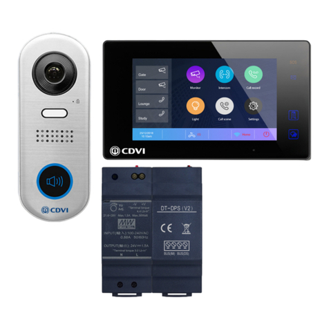
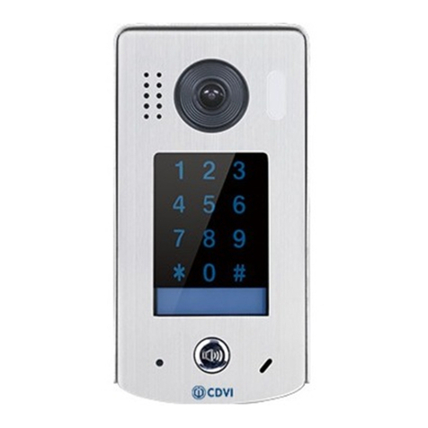
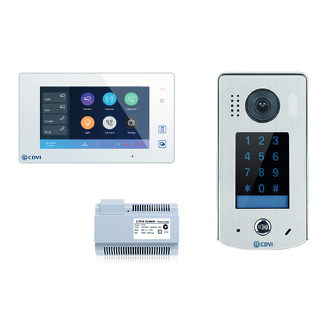
CDVI CDV-DDP-F User manual

2EASY 2-wire Video Door Station with
Built-in Reader
CDV-DDP-F,
CDV-DDP-RH
EN
WARRANTY
YEAR
2

EN EN
2
CDV-DDP-F, CDV-DDP-RH
2EASY 2-wire Video Door Station with Built-in Reader
1] CONTENTS
2] Parts and Functions 3
3] Terminal Descriptions 3
4] Installation 4
5] Electric Lock Connection 5
6] System Wiring 7
7] Settings 8
8] Code Unlock Function 11
9] User Card Management 12
10] Cable Requirements 14
11] Product Specications 14
Title Page

EN EN
3
CDV-DDP-F, CDV-DDP-RH
2EASY 2-wire Video Door Station with Built-in Reader
2] PARTS AND FUNCTIONS
3] TERMINAL DESCRIPTIONS
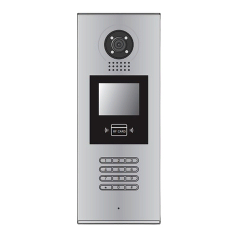
Camera Lens
Night View LED
Speaker
Adjustable Camera
Connectiong Port
With rainy cover
350 mm
128 mm
1 2 3
654
7 8 9
#0
*
LCD Screen
ID Card Window
Digital Keypad
Microphone
12
3
Touch Key
RF CARD
L1
T/R -
CN-LK
T/R+
J/KMB JP-LK
Bus
SD Card Slot
EB+
EB-
N.O
LK+
LK-
+12V
L2
12
3
12
3
• 12V: +12Vdc power output.
• LK-(GND): Power ground.
• LK+(COM): Common contact of the relay.
• NO: Normally open contact of the relay.
• EB+/EB-: Exit button connection port.
• JP-LK: For electric lock safety type setting.
• T/R-: USB-RS485 communication terminal negative.
• T/R+: USB-RS485 communication terminal negative.
• BUS (L1,L2): No polarity BUS line.
Connecting Port

EN EN
4
CDV-DDP-F, CDV-DDP-RH
2EASY 2-wire Video Door Station with Built-in Reader
4] INSTALLATION
Surface Mount - CDV-DDP-RH
Flush Mount - CDV-DDP-F
1 2
4 5 6
Drill holes in the wall to match the size of
screws and attach the rainy cover to the wall.
Attach screws to fix the
metal box
Attach the unit to the rainy
cover correctlly
The last view for all mounting
The view for rainy
cover after mounted
Adjust the camera angle and attach the
metal to the panel and wire correctly.
Camera
angle
3
Drill holes in the wall to mach the size
of the wall plugs and mount the surface
housing to the wall.
Surface housing after mounting. Adjust the camera angle. Attach the back
box to the panel and wire correctly.
Screw the back box to the panel. Attach the unit to the surface housing
correctly.
1 2 3
4
7
5 6
Drill a hole and attach the
rainy cover to it
Attach screws to fix the
metal box
Attach the unit to the rainy
cover correctlly
Attach the baffle to protect
the unit from droping
The last view for all mounting
The view for rainy
cover after mounted
Adjust the camera angle and attach the
metal to the panel and wire correctly.
Camera
angle
1
47
m
m
3
95
m
m
4
2mm
RF CARD
Drill holes and mount the ush housing
to the wall.
Adjust the camera angle, attach the
back box to the panel and wire correctly.

EN EN
5
CDV-DDP-F, CDV-DDP-RH
2EASY 2-wire Video Door Station with Built-in Reader
5] ELECTRIC LOCK CONNECTION
1. The rated power of the lock must be less than 12Vdc 300mA when using internal
power supply mode.
2. The GND must connect to the negative of the lock, and the COM connect to the
positive.
3. Jumper set to 1-2 position for Power-off-to-Unlock Fail Safe type (Normally closed);
Jumper set to position 2 & 3 for Power-on-to-Unlock Fail Secure type (Normally
open).
4. If different unlocking time is required, change the Unlock Timing on the door station.
(See Debug State p. 8 / Press [1#] --> [1] Installer Set up --> [2] Unlocking time.)
1 2 3
4
7
5 6
Drill a hole and attach the
rainy cover to it
Attach screws to fix the
metal box
Attach the unit to the rainy
cover correctlly
Attach the baffle to protect
the unit from droping
The last view for all mounting
The view for rainy
cover after mounted
Adjust the camera angle and attach the
metal to the panel and wire correctly.
Camera
angle
1
47
m
m
3
95
m
m
4
2mm
RF CARD
Attach the unit to the surface housing
correctly.
Screw the back box to the panel. Attach the bafe to protect the unit
from lifting.
Door Lock Controlled with Internal Power
Using the power of the system, the electric lock can be connected directly to the door
station without an additional power supply.
Note: The door station can only output 12Vdc at 300mA, therefore limiting the types
of lock that can be connected.

EN EN
6
CDV-DDP-F, CDV-DDP-RH
2EASY 2-wire Video Door Station with Built-in Reader
FAIL SAFE Lock FAIL SECURE Lock
JP_LK
12V 300mA
Jumper set to 2-3 position
+
-+12V
LK - (GND)
LK+(COM)
N.O.
EB+
EB -
1
2
3
set to Normally open on the
Unlock Relay mode
12V 300mA
Jumper set to 1-2 position
+12V
LK - (GND)
LK+(COM)
N.O.
EB+
EB -
+
-
set to Normally Closed on the
Unlock Relay mode
JP_LK
1
2
3
Door Lock Controlled with External Power
Note: When the electric lock is over 12 Vdc or higher than 300mA, an additional power
supply for the lock is required.
1. The power supply for the lock must be less than 48Vdc 1.5A.
2. The Jumper must be removed when using external power supply.
3. The default setting is:
• Power-on-to-Unlock Fail Secure type (Normally open)
• If using Power-off-to-Unlock (Fail Safe), change the Unlock Relay mode to
Normally closed.
4. If a different unlock time is required, change the unlock time at the door station.
(See Debug State p. 8 / Press [1#] --> [1] Installer Set up --> [2] Unlocking time.)
FAIL SAFE Lock FAIL SECURE Lock
+
+
-
-
+12V
LK - (GND)
LK+(COM)
N.O.
EB+
EB -
Remove the Jumper
set to Normally Open on the
Unlock Relay mode (default)
JP_LK
1
2
3
Note: Cut off this line when
using external power supply
+12V
LK - (GND)
LK+(COM)
N.O.
EB+
EB -
Remove the Jumper
set to Normally Closed on the
Unlock Relay mode
+
+
-
-
JP_LK
1
2
3
Note: Cut off this line when
using external power supply

EN EN
7
CDV-DDP-F, CDV-DDP-RH
2EASY 2-wire Video Door Station with Built-in Reader
6] SYSTEM WIRING
Code=0
OFF ON
OFF ON
DBC4A
A B C D
DBC4A
A B C D
Impedance
switch
Impedance
switch
NOTE:Here we take DT47M(the monitor) for example.
Code=2
Code=1
Code=3
Code=28
Code=30
Code=29
Code=31
1 2 3
654
7 8 9
#0
*
RF CARD
DPS(V2)HDR-30-24
PC7
Note: System wiring using the CDV-47DX monitor.

EN EN
8
CDV-DDP-F, CDV-DDP-RH
2EASY 2-wire Video Door Station with Built-in Reader
7] SETTINGS
Debug Stage
[ 9 0 0 8 ]
Please Input Password
1 2 3
654
7 8 9
#0
*
RF CARD
>> Debug State <<
1-# Tools
0-# Redial
2-# Exits
When the door station
is in Standby, press ‘#’
key.
Enter ‘9008’, then
enter the Admin Code.
(66666666 by default)
Debug state menu is
launched.
Descriptions:
0-#: Call Monitor again
1-#: Go to Tools setting
2-#: Exit out Debug
State
The Debug State is the starting point for using all the functions on CDV-DDP.
Adjusting the Talk Volume
In Debug State, calling and conversations are adjustable. You can adjust the volume by
selecting the numbers 0 to 9.
Press [2#] to exit the Debug State.
Debug State
1. Installer Setup
2. Setup
3. Card Manage
4. Online Monitors
5. Online Devices
6. Voltage Measure
Pres NO.
to select
*Back
Tools
>> Debug State <<
0-# Redial
2-# Exits
1-# Tools
When working in Debug State press “1#” to enter tools page.
The Debug Tools are described in the table below:
Item Sub-menu
1. Installer Setup 1. ID Code [0]
2. Unlock Timing [01]
3. Unlock Output [0]
4. Monitor Timing [600]
5. Doorplate Mode [1]
6. Waiting Timing [040]
7. Talking Timing [090]
8. Installer Code ...
9. Default ...

EN EN
9
CDV-DDP-F, CDV-DDP-RH
2EASY 2-wire Video Door Station with Built-in Reader
Item Sub-menu
2. Setup 1. Language [0]
2. Tone Select [01]
3. Tone Volume [3]
4. Unlock Code [1111]
5. Work Mode [0]
6. Clock ...
7. Setup Code ...
8. About ...
9. Default ...
3. Card Manage 1. Add Card ...
2. Delete By Card
3. Delete By M.code
4. Cards Information
5. Format
4. Online Monitors To search the online monitors,
enter the monitor code number
to search
5. Online Devices To search the online door
stations. (Max.4 door stations
can be searched)
6. Voltage Measure To check the voltage of the
monitor, note that the monitor
must be online.
1. Installer Setup
Item Description Factory Setting
ID Code
If only one door station is installed in this building,
set to 0;
If multiple door stations are installed, primary door
station must be set to 0, and other sub-door stations
must be set from 1 to 3. Note that max. 4 door
stations are available in one building
[0] Single
Unlock Timing To set the duration of the lock release when the door
release is activated from 01 to 99 seconds.
[01] 1 second
Unlock Output To set the unlock mode to match the lock type. Range
from 0 to 1.
0: Power-on-to-Unlock Mode(Normally Open Mode)
1: Power-off-to-Unlock Mode(Normally Closed Mode)
0
Monitor Timing To show the monitor time: Range from 6s to 600s 600s
Doorplate Mode Auto Call: Setting range from 0 to 1. 0: enter the
call code to call. 1: input “#” to conrm dialling after
input a complete call codes.
Building No.:0~4 digit for the Building No., 0 means
without a Building No. The door station will only call
to local monitors connected.
Room No.: 2~4 digit for the Room No. Enter 2 digits
for the Room No. to call.
Input No.: 2~8 maximum digit for input codes, at
least 2 digits.
Call Mode: Reserve, always set it to 2.
Waiting Timing To show the calling wait time: 6s to 600s 40s
Talking Timing To show the limitation time for talking: 6s to 600s 90s
Installer Code... To change door station administrator code [66666666]
Default... Restore Installer Setup to factory settings, except
access card info. This operation is irreversible.
EN EN
10
CDV-DDP-F, CDV-DDP-RH
2EASY 2-wire Video Door Station with Built-in Reader
2. Setup
Item Description Factory Setting
Language Reserved. 0
Tone Select Select the tone of the door station when calling. 01
Tone Volume Adjust the tone volume for door station when calling:
Range 01 to 15
3
Unlock Code To change unlock code in Common Code Unlock
mode, in 4-digits format. 1111 is the default unlock
code.
1111
Work Mode 0: Standard work mode;
1: DJ work mode;
2: Router work mode;
3. Gateway work mode.
0
Clock... To set date and time.
Date format:
• If set to 0 date format is DD/MM/YY.
• If set to 1 date format is MM/DD/YY.
Time format:
• If set to 0, time format is 24 hour standard.
• If set to 1, time format is 12 hour standard.
Setup Code To change the Program Code. [88888888]
About... 1. Hardware version: To show the Door Station
(including ACS) hardware information
2. Software version: To show the Door Station
(including ACS) software information
3. Manufacture Date: To show the manufacturing
date
4. Dialing Counts: To show the call operation counts
5. Calls Counts: To show the established calling
counts
6. Unlock Counts: To show the unlock operation
counts
Default... Restore all Setup parameters to factory settings. This
operation is irreversible.
2. Card Manage
Item Description
Add Card To add the user card
Delete By Card To delete card by user card
Delete by M. Code To delete card by room code
Card Information To show the details about cards
Format To format card details

EN EN
11
CDV-DDP-F, CDV-DDP-RH
2EASY 2-wire Video Door Station with Built-in Reader
8] CODE UNLOCK FUNCTION
[ - - - - ]
Please Input Password
1 2 3
654
7 8 9
#0
*
RF CARD
1 2 3
654
7 8 9
#0
*
RF CARD
[8017 ]
iDoor Open
Refer to the following operations:
When the Door Station
is in standby, Press “#”.
Enter 4 digits Unlock
Code directly.
If veried correctly, the
door opens.
Changing the Unlock Code
If the door station is in Debug State press “1#” to activate Tools Menu, then select “2”
to enter setup page. Finally, select 4.
When the door station is in standby mode follow the steps below:
[ 8002 ]
Please Input Password
1 2 3
654
7 8 9
#0
*
RF CARD
*Cancel
Long press[ ] to enter private code setting
[ - - - - ]
( * * * *)
# Save
4. Unlock Code[1111]
1. Language [1]
3. Tone Volume[03]
4. Unlock Code [1111]
5. Work Mode
6. Clock
7. Setup Code
8. About
9. Default
Press No.
to select
*Back
Setup
2. Tone Select [03]
Press “#”, Enter “8002”,
then enter Setup Code or
Admin Code (88888888
or 66666666 by default)
Press “4” to enter unlock
code item.
Enter 4 digits number,
then press “#” to update
4. Unlock Code [1111]
[----]
(****)
[005]
Input setting code
[009]
Input room number
Setting code: 005
RF CARD
4. Unlock Code
4. Unlock Code [---] [----]
[8888]
Input new password
Setting code: 005
4. Unlock Code [009] [----]
[8888]
Input new password
Setting code: 005
4. Unlock Code [009] [8888]
*Cancel # Save *Cancel # Save *Cancel # Save *Cancel # Save *Cancel # Save
Long press[ ] to enter private code setting Long press[ ] to enter public code setting
At this point you can also set the Private Unlock Code by following these steps:
Long press
button
Enter setting code
(001~200), then
press # to save.
Input room
number, then
press # to save.
Input new
password, then
press “#“ to save.

EN EN
12
CDV-DDP-F, CDV-DDP-RH
2EASY 2-wire Video Door Station with Built-in Reader
9] USER CARD MANAGEMENT
This section explains how to congure the key fob function on CDV-DDP.
A key fob can be used to release the lock by presenting an enrolled fob to the panel
reader. A total of 320 key fobs can be registered within one door station. When presenting
the fob to the door station, the distance must be less than 3 cm.
Note: Key fobs must be registered to each door station on the system to open the local
door.
Key Fob Registration
All the registered key fobs are called User Cards. New cards need to be registered one
by one to the Door Station to become a valid User Card.
Every User Card is related to a certain Monitor Address (Flat code).
When the door station is in standby; press [#] --> [9008] --> Password ([66666666
by default]) to get into the Debug Mode Menu, then Press [1 #] --> [3] Card Manage
-->[1] Add Card to get into the Add Card page.
1. AddCard ...
* Back # Save
Please Input Room Code
[ - - - ]
1. AddCard ...
* Back # Save
Show the card
[ 0 0 1 ]
1. AddCard ...
* Back # Save
[ 0 0 1 ]
C a r d numbs :15977131
Show The Card
User
Card
iUpdated
Enter ‘Add Card’ menu.
The Room code is asked.
Enter the Room/ Monitor
code.
Present the card that
you want to register.
Delete User Card
Registered User Cards can be deleted at the door station. Once deleted, the key fob
cannot open the door. They can be re-registered to become a valid User Card again.
There are two ways to delete User Card:
1. Delete by card: Present the unwanted card(s) when the Door station is in ‘Delete
Card’ mode.
2. Delete by room number: Delete all the registered User Cards related to that room.
number.

EN EN
13
CDV-DDP-F, CDV-DDP-RH
2EASY 2-wire Video Door Station with Built-in Reader
‘Delete By Card’
In Debug State:
1. Press [1 #]
2. Enter [3] Card Manage
3. Enter [2] Delete By Card to enter
‘Delete by Card’ page.
4. Present the cards you want to delete
one by one.
2. Delete By Card ...
* Back # Save
Show The Card
2. Delete By Card ...
* Back # Save
User
Card
C a r d numbs:15977131
Show The Card
iUpdated
‘Delete by M.code’
In Debug State:
1. Press [1 #]
2. Enter [3] Card Manage
3. Enter [3] Delete By M.Code to enter
4. ‘Delete by M.Code’ page.
5. Enter the Room code and press # to
conrm.
6. All associated room cards will be
deleted.
3. Delete By M.code
* Back # Save
Please Input Room Code
[ - - - ]
3. Delete By M.code
* Back # Save
[ 0 0 1 ]
Please Input Room Code
iUpdated
Card Information
Format
Enter the Card Information page. The
screen will display the authorised User
Cards count and card read access
events count.
4. Cards Information
* Back # Save
Card Count: 320
1. Enter the Card Format page.
2. Enter the 8 digit installer password
(66666666) by default), then press
# key to save.
3. Format operation is activated.
All card information will be cleared.
5. Format
* Back # Save
Please Input Password
[ - - - - - - - - ]

EN EN
14
CDV-DDP-F, CDV-DDP-RH
2EASY 2-wire Video Door Station with Built-in Reader
10] CABLE REQUIREMENTS
Feature Description
Power Supply 24Vdc
Power Consumption StandBy: 94mA
Working status: 157mA
Wiring 2-wire, no polarity
Camera 1/4 ACS 4T image sensor with DSP processor
Screen, Resolution 3.5 inch TFT, 320 (R,G,B) X 240 pixels
Video Signal CCIR/ EIA optional
Dimensions 350(H) × 128(W) × 46(D) mm
Operating Temperature 5° to 45°C
11] SPECIFICATIONS
Cable Usage A
<20m
monitors
A
>20m
monitors
B
<20m
monitors
B
>20m
monitors
C
<20m
monitors
C
>20m
monitors
Belden 9470 UTP
2x0.75mm2
60 50 60 30 30 20
Belden 8471 UTP
2x1mm2
80 70 80 50 40 30
Cable and distance (unit: m)
Recommended cable:
16AWG, Belden 8471
PC7
A
Note:
Use DBC4A < 8 CDV-47DX monitors.
Use DBC4R > 8 CDV-47DX monitors.

EN EN
15
CDV-DDP-F, CDV-DDP-RH
2EASY 2-wire Video Door Station with Built-in Reader
Notes
.......................................................................................................................
.......................................................................................................................
.......................................................................................................................
.......................................................................................................................
.......................................................................................................................
.......................................................................................................................
.......................................................................................................................
.......................................................................................................................
.......................................................................................................................
.......................................................................................................................
.......................................................................................................................
.......................................................................................................................
.......................................................................................................................
.......................................................................................................................
.......................................................................................................................
......................................................................................................................
.......................................................................................................................
.......................................................................................................................
.......................................................................................................................
.......................................................................................................................
.......................................................................................................................
.......................................................................................................................
.......................................................................................................................
.......................................................................................................................

www.cdvigroup.com
CDVI Group
FRANCE (Headquarters)
Phone: +33 (0) 1 48 91 01 02
CDVI FRANCE + EXPORT
+33 (0) 1 48 91 01 02
www.cdvi.com
CDVI AMERICAS [CANADA - USA]
+1 (450) 682 7945
www.cdvi.ca
CDVI BENELUX [BELGIUM - NETHERLANDS - LUXEMBOURG]
+32 (0) 56 73 93 00
www.cdvibenelux.com
CDVI GERMANY
+49 (0) 175 2932 901
www.cdvi.de
CDVI TAIWAN
+886 (0) 42471 2188
www.cdvichina.cn
CDVI SUISSE
+41 (0) 21 882 18 41
www.cdvi.ch
CDVI CHINA
+86 (0) 10 84606132/82
www.cdvichina.cn
CDVI IBÉRICA [SPAIN - PORTUGAL]
+34 (0) 935 390 966
www.cdviberica.com
CDVI ITALIA
+39 (0) 321 90 573
www.cdvi.it
CDVI MAROC
+212 (0) 5 22 48 09 40
www.cdvi.ma
CDVI SWEDEN
[SWEDEN - DENMARK - NORWAY - FINLAND]
+46 (0) 31 760 19 30
www.cdvi.se
CDVI UK [UNITED KINGDOM - IRELAND]
+44 (0) 1628 531300
www.cdvi.co.uk
CDVI POLSKA
+48 (0) 12 659 23 44
www.cdvi.com.pl
All the information contained within this document (pictures, drawings, features, specications and dimensions)
could be perceptibly different and can be changed without prior notice. - Oct 2021
*DT-ENG-DMR18S-V2*
Reference : DT-ENG-DMR18S-V2
Extranet : CDVI_CDV-DDP_IM_01_EN_A4_C
This manual suits for next models
1
Table of contents
Other CDVI Intercom System manuals

CDVI
CDVI CDV96KP User manual

CDVI
CDVI 2Easy CDV4796KP-DX User manual

CDVI
CDVI 2EASY CDV-850IP User manual

CDVI
CDVI CDV-91 User manual

CDVI
CDVI CDV-91IP User manual

CDVI
CDVI CDV91S User manual

CDVI
CDVI 2EASY CDV-91S User manual

CDVI
CDVI CDV97-8ID Series User manual

CDVI
CDVI 2EASY CDV-47DX User manual

CDVI
CDVI CDV96KP User manual
Popular Intercom System manuals by other brands

PACH & COMPANY
PACH & COMPANY AeGIS NPB9000P Series Installation and programming manual

ARCHEAN
ARCHEAN Audio Accessibilite DCSTS-K072 Installation & user guide

Panasonic
Panasonic VL-MWD501 installation guide

Zamel
Zamel VP-810BHD manual

Intratone
Intratone Intracall 14-0144 Installing and connecting

Akuvox
Akuvox R28 Series Administrator's guide