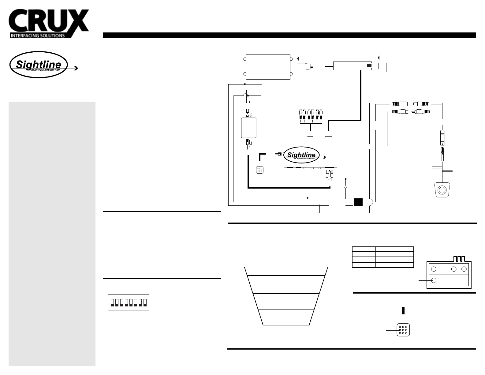
VIDEO INPUT
CONNECTIONS 6-PIN
(male plug)
AUDIO
OUTPUTS
VDO 1
(input) VDO 2
(input) CAM
(input)
10-PIN
(female plug)
BLACK
CONNECT BEHIND
DISPLAY
(NOT BEHIND RADIO)
15 ft
(extension)
VIDEO/ POWER
CONNECTION
GREEN/
REVERSE WIRE
RED/
REVERSE
TRIGGER
YELLOW RCA
CONNECTION
FOR CAMERA
INPUT
(male end goes to interface)
SWITCH
(input)
SWITCH
BUTTON
CAN-BUS
INTERFACE
VIDEO INTERFACE
TO FACTORY
DISPLAY
FACTORY
HARNESS
4-PIN BARREL
CONNECT FOR CAMERA
POWER AND SIGNAL
DIP
SWITCHES
BLACK/
GROUND TO CAMERA
RCA INPUT
.....
..... CAR SIDE
BLUE
(Front/ Rear Camera View)
CONNECT TO FOR FRONT
WHITE
(Parking Lines)
CONNECT TO TURN OFF
10-PIN
(female port) 10-PIN
(male plug)
LED
BROWN/ GROUND
GRAY/ CAN-LOW
RED/ CONSTANT
BLUE/ CAN-HIGH
POWER DOWN
CIRCUIT
RED/ REVERSE TRIGGER INPUT
YELLOW/ 12V CONSTANT
BLACK/ GROUND GREEN/ 12V OUTPUT (2.7A)
12-PIN
(male plug)
4-PIN
(male plug)
8-PIN
(male plug)
DIODE/
1N4001
FROM OEM REVERSE LIGHT
MERCEDES BENZ:
2007 - 2009 S-550
RVCMB-78S CONNECTIONS OVERVIEW
TROUBLE SHOOTING
1. No video display while in reverse.
- Make sure the dip switches are in the correct position. More support contact us.
The parking lines are there to assist you while reversing.
What the lines mean:
Yellow Line: CLEAR
Purple Line: GETTING CLOSE
Red Line: WARNING - VERY CLOSE
To remove the parking lines simply cut the GREEN wire located near the
4 pin tail connector in the truck.
RED
YELLOW
GREEN
We recommend reading this installation guide rst before starting any
work. Following these instructions from “Start” to” Finish” will ensure a
smooth and hassle free installation. We oer telephone support
M-F 9:00 AM – 5:00 PM PDT at 1 (855) 822-1348. We are here to help.
PARTS INCLUDED:
(1) Camera (MB-78S)
(1) 15 ft. Extension
(1) MB-78S Interface
(1) MB-78S Can-Bus Interface
(1) MB-78S Harness
(1) Instruction
Camera Specications:
- Lens Angle 170 Degrees
- Resolution 420 TV Lines
- Min. Illumination 0.2Lux
- Voltage 12v
- Operating Temp. -22˚F - 176˚F
- NTSC
- Reference Lines
- Shutter Speed 1/60s - 20us
- Waterproof
- Pixels 656 x 492
PRECAUTIONS:
- Remove the negative side of the battery to avoid any short circuits
during the installation.
- Do not install the interface near any major components or near the
HVAC system. This may cause damage or overheating to the vehicle.
PRELIMINARY:
Please read the entire manual before installing this interface.
INSTALLING THE CAMERA AND CABLE
1. Remove the rear lip panel.
2. Drill a 5/8 size hole in the location
3. Fish the wires through the drilled hole and through the pass through
into the trunk/cargo area.
4. Remove the factory display to gain access to the factory connectors.
5. Route the wires towards the display and make the power and video
connections. For powering up the (RED) camera wire, use the
(GREEN) 12v output from the POWER DOWN CIRCUIT board.
6. Using the T-Harness provided make the 10-Pin connections.
Tap the CAN wires behind the factory display, not behind the radio.
7. Test the camera before re-installing the dash.
REAR-VIEW INTEGRATION w/ CAMERA FOR MERCEDES BENZ S-CLASS 2007-2009
PARKING LINE
Rev. 062314
WORKS WITH ANY
10-PIN LVDS CONNECTER
To toggle through the video inputs on the interface please press once on
provided switch button.
SWITCHING VIDEO INPUTS ON SWITCH
SETTING THE DIP SWITCHES ON MAIN INTERFACE
SWITCH
BUTTON
PRESS
ONCE
TO ENABLE VIDEO
1. RGB Input Enable
2. AV1 Input Enable
3. AV2 Input Enable
4. 800x400 (OFF) or 480x240 (ON) Enable
5. AV4. Use GREEN wire to enable.
6. IR Programming/ Display Calibrate
7. Screen Size Selection
OFF
1 2 3 4 5 6 7 8
DIP 1: ON = RGB Enable , OFF = Disable
DIP 2: ON = AV1 Enable , OFF = Disable
DIP 3: ON = AV2 Enable , OFF = Disable
DIP 4: ON = RGB HD 800x480 or VGA 640x480 ,
OFF = RGB Normal or NTSC 480x240
DIP 5: ON = Aftermarket Camera , OFF = for Factory Camera equipped
DIP 6: ON = IR program mode , OFF = Normal Mode
DIP 7: OFF , 8 = OFF = 7 inches screen 800x400 resolution
DIP 7: OFF , 8 = ON = 6 inches Screen 480x240 resolution
DIP 7: ON , 8 = ON = 5 inches Screen 280x100 resolution
Behind the factory display (not the radio) there is a 8-Pin connector
where you will be tapping your CAN wires. Locations go as follows:
Blue CAN-LOW
Blue White CAN-HIGH
Red/Blue 12v Constant
Brown Ground
FACTORY DISPLAY CONNECTOR (TAP HERE)
Blue
Blue/White
Red/Blue Brown
SEE FACTORY
DISPLAY SECTION
FOR INFORMATION


