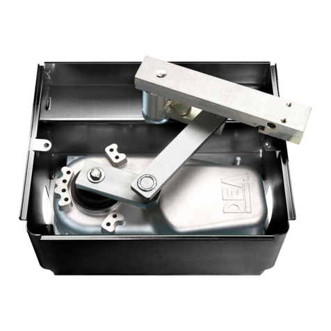
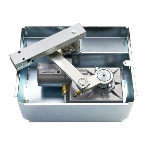
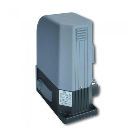
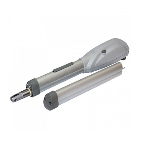
Dea ghost 200 Product manual

GHOST
200
I21001 Rev. 10 (28-09-2022)
Operatore elettromeccanico interrato per cancelli ad anta
Istruzioni d’uso ed avvertenze
Underground electro-mechanical operator for swing gates
Operating instructions and warnings
Motoréducteur électromécanique pour portails battants
Notice d’emploi et avertissements
Elektromechanischer Unterflurantrieb für Drehtore
Bedienungsanleitung und Hinweise
Operador electromecánico para puertas con hoja batiente
Instrucciones de uso y advertencias
Operador electromecânico para portões de folha batente
Instruções para utilização e advertências
Siłownik elektromechaniczny do bram skrzydłowych
Instrukcja montażu i użytkowania
Электромеханический привод для распашных ворот
Инструкции ипредупреждения


GHOST 200
1
IT
GHOST 200
Operatore elettromeccanico interrato
per porte ad anta battente
Istruzioni d’uso ed avvertenze
Sommario
1Riepilogo Avvertenze 16Messa in Servizio 7
2Descrizione Prodotto 36.1 Collaudo dell’Impianto 7
3Dati Tecnici 36.2 Sblocco e manovra manuale 7
4Installazione e Montaggio 37Manutenzione 7
5Collegamenti Elettrici 48Dismissione Prodotto 8
1 RIEPILOGO AVVERTENZE
ATTENZIONE!IMPORTANTI ISTRUZIONI DI SICUREZZA. LEGGERE ESEGUIRE ATTENTAMENTE TUTTE LE AVVERTENZE
ELE ISTRUZIONI CHE ACCOMPAGNANO IL PRODOTTO POICHÉ UN’INSTALLAZIONE ERRATA PUÒ CAUSARE DANNI A
PERSONE, ANIMALI OCOSE. LEAVVERTENZE ELE ISTRUZIONI FORNISCONO IMPORTANTI INDICAZIONI RIGUARDANTI
LA SICUREZZA, L’INSTALLAZIONE, L’USO ELA MANUTENZIONE. CONSERVARE LE ISTRUZIONI PER ALLEGARLE AL
FASCICOLO TECNICO EPER CONSULTAZIONI FUTURE.
ATTENZIONE L’apparecchio può essere utilizzato da bambini di età non inferiore
agli 8 anni, persone con ridotte capacità fisiche, mentali o sensoriali, o in generale da
qualunque persona priva di esperienza o comunque della necessaria esperienza, purchè
sotto sorveglianza oppure che le stesse abbiano ricevuto una corretta formazione all’uso
sicuro dell’apparecchio e alla comprensione dei pericoli ad esso inerenti.
ATTENZIONE Non permettere ai bambini di giocare con l’apparecchio, i comandi fissi o
con i radiocomandi dell’impianto.
ATTENZIONE L’utilizzo del prodotto in condizioni anomale non previste dal costruttore
può generare situazioni di pericolo; rispettare le condizioni previste dalle presenti
istruzioni.
ATTENZIONE DEA System ricorda che la scelta, la disposizione e l’installazione di tutti
i dispositivi ed i materiali costituenti l’assieme completo della chiusura, devono avvenire
in ottemperanza alle Direttive Europee 2006/42/CE (Direttiva macchine), 2014/30/UE
(compatibilità elettromagnetica), 2014/35/UE (apparecchi elettrici a bassa tensione).
Per tutti i Paesi extra Unione Europea, oltre alle norme nazionali vigenti, per un sufficiente
livello di sicurezza si consiglia il rispetto anche delle prescrizioni contenute nelle Direttive
sopraccitate.
ATTENZIONE In nessun caso utilizzare l’apparecchio in presenza di atmosfera eplosiva
o in ambienti che possano essere aggressivi e danneggiare parti del prodotto. Verificare
che le temperature nel luogo di installazione siano idonee e rispettino le temperature
dichiarate nell’etichetta del prodotto.
ATTENZIONE Quando si opera con il comando “uomo presente”, assicurarsi che non ci
siano persone nella zona di movimentazione dell’automatismo.

GHOST 200
2
ATTENZIONE Verificare che a monte della rete di alimentazione dell’impianto, vi sia un
interruttore o un magnetotermico onnipolare che consenta la disconnessione completa
nelle condizioni della categoria di sovratensione III.
ATTENZIONE I conduttori a bassissima tensione di sicurezza, devono essere fisicamente
separati (almeno 4mm in aria) dai conduttori in bassa tensione, oppure devono essere
adeguatamente isolati con isolamento supplementare avente spessore di almeno 1 mm.
ATTENZIONE Se il cavo di alimentazione è danneggiato, esso deve essere sostituito
dal costruttore o dal suo servizio di assistenza tecnica o comunque da una persona con
qualifica similare, in modo da prevenire ogni rischio.
ATTENZIONE Qualsiasi operazione d’installazione, manutenzione, pulizia o riparazione
dell’intero impianto devono essere eseguite esclusivamente da personale qualificato;
operare sempre in mancanza di alimentazione e seguire scrupolosamente tutte le norme
vigenti nel paese in cui si effettua l’installazione, in materia di impianti elettrici.
La pulizia e la manutenzione destinata ad essere effettuata dall’utilizzatore non deve
essere effettuata da bambini senza sorveglianza.
ATTENZIONE L’utilizzo di parti di ricambio non indicate da DEA System e/o il
riassemblaggio non corretto possono causare situazioni di pericolo per persone, animali
e cose; possono inoltre causare malfunzionamenti al prodotto; utilizzare sempre le parti
indicate da DEA System e seguire le istruzioni per l’assemblaggio.
ATTENZIONE Cambiare la regolazione della forza in chiusura, può portare a situazioni
di pericolo. Pertanto, l’aumento della forza in chiusura, deve essere eseguito solo da
personale qualificato. Dopo la regolazione, il rispetto dei valori dei limiti normativi deve
essere rilevato con uno strumento per misure delle forze d’impatto. La sensibilità del
rilevamento ostacoli può essere adeguata in modo graduale alla porta (vedi istruzioni
per la programmazione). Dopo ogni regolazione manuale della forza, si deve verificare il
funzionamento del dispositivo anti schiacciamento. Una modifica manuale della forza può
essere effettuata solo da personale qualificato eseguendo test di misurazione secondo
EN 12445. Una modifica della regolazione forza deve essere documentata nel libretto
macchina.
ATTENZIONE La conformità del dispositivo di rilevamente degli ostacoli interno ai
requisiti della norma EN12453 è garantito solo se con utilizzo in abbinamento con motori
provvisti di encoder.
ATTENZIONE Eventuali dispositivi di sicurezza esterni utilizzati per il rispetto dei limiti
delle forze d’impatto devono essere conformi alla norma EN12978.
ATTENZIONE InottemperanzaallaDirettivaUE2012/19/CEsuirifiutidiapparecchiature
elettriche ed elettroniche (WEEE), questo prodotto elettrico non deve essere smaltito
come rifiuto municipale misto. Si prega di smaltire il prodotto portandolo al punto di
raccolta municipale locale per un opportuno riciclaggio.
TUTTO QUELLO CHE NON ÈESPRESSAMENTE PREVISTO NEL MANUALE D’INSTALLAZIONE, NON ÈPERMESSO. IL BUON
FUNZIONAMENTO DELL’OPERATORE ÈGARANTITO SOLO SE VENGONO RISPETTATI IDATI RIPORTATI. LADITTA NON
RISPONDE DEI DANNI CAUSATI DALL’INOSSERVANZA DELLE INDICAZIONI RIPORTATE IN QUESTO MANUALE. LASCIANDO
INALTERATE LE CARATTERISTICHE ESSENZIALI DEL PRODOTTO, LA DITTA SI RISERVA DI APPORTARE IN QUALUNQUE
MOMENTO LE MODIFICHE CHE ESSA RITIENE CONVENIENTI PER MIGLIORARE TECNICAMENTE, COSTRUTTIVAMENTE E
COMMERCIALMENTE IL PRODOTTO, SENZA IMPEGNARSI AD AGGIORNARE LA PRESENTE PUBBLICAZIONE.

GHOST 200
3
IT
2 DESCRIZIONE DEL PRODOTTO
Modelli e contenuto imballo
Con la denominazione GHOST 200 viene identificata una serie di operatori elettromeccanici interrati per l’automazione di cancelli ad
anta battente con caratteristiche diverse per quanto riguarda la tensione di alimentazione del motore e la presenza di encoder.
Gli accessori di completamento sono riportati in tabella “ACCESSORI PRODOTTO” (pag. 70).
GHOST 200 è costituito essenzialmente da un motoriduttore meccanico che pone in rotazione un braccio snodato; tale braccio è as-
semblato al cancello da movimentare tramite il gruppo leva della cassa di fondazione. Il gruppo leva, che sarà adeguatamente saldato al
momento dell’installazione al cancello, incorpora anche il dipositivo di sblocco dell’automatismo che ne permette l’apertura in assenza
di tensione.
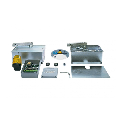
Ispeziona il “Contenuto dell’imballo” (Fig. 1) confrontandolo con il tuo prodotto, ti potrà essere utile durante l’assemblaggio.
Trasporto
GHOST 200 è sempre fornito imballato in scatole che forniscono una adeguata protezione al prodotto; fare comunque attenzione a
tutte le indicazioni eventualmente fornite sulla scatola stessa per lo stoccaggio e la manipolazione.
3 DATI TECNICI
200 - 200CL
200/EN - 200/CLEN 200L - 200L/CL 200/24 - 200/24CL
Tensione alimentazione motore (V) 230-240 V ~ (50/60 Hz) 24 V
Potenza assorbita (W) 400 330 150
Coppia massima (Nm) 320 300 210
Ciclo di lavoro (manovre/ora) 20 - 28 (200/EN & 200/CLEN) 18 40
N° max manovre in 24 ore * 200 280
Condensatore incorporato (μF) 12,5 /
Temperature limite di funzionamento (°C) -20 ÷ 50 °C
Termoprotezione motore (°C) 150 °C /
Tempo di apertura 90° (s) * 17 26 16
Grado di apertura massima 107°
Peso del prodotto con imballo (kg) 14,5 14
Pressione sonora emessa (dBA) < 70
Grado di protezione IP67
* I dati sono riferiti all’utilizzo in abbinamento a centrali di comando serie NET e con parametri di velocità e di rallentamento
impostati di default.
4 INSTALLAZIONE E MONTAGGIO
4.1 Per una soddisfacente posa in opera del prodotto è importante:
• Verificare che la struttura sia conforme alle norme vigenti e successivamente definire il progetto completo dell’apertura automatica;
• Verificare che il cancello sia ben bilanciato e che non presenti punti d’attrito sia in chiusura che in apertura;
• Individuare una zona che consenta una manovra manuale fluida e in sicurezza del motoriduttore;
• Verificare che l’ingombro della cassa di fondazione sia compatibile con la zona prescelta per il montaggio (Fig. 2);
• Prevedere una battuta di arresto in chiusura e possibilmente anche in apertura;
• Utilizzare il grafico lunghezza/peso e le quote d’installazione fornite (Fig. 4) per un corretto posizionamento della cassa rispetto l’anta
da movimentare.

GHOST 200
4
4.2 Definiti e soddisfatti i suddetti requisiti preliminari, procedere al montaggio:
• Eseguire uno scavo adeguato al tipo di terreno usando come riferimento le quote indicate in Fig. 3;
• Predisporre un numero adeguato di canalette per il passaggio dei cavi elettrici e per il drenaggio al fine di evitare il ristagno dell’ac-
qua;
ATTENZIONE Tutti i cablaggi dell’operatore devono essere effettuati all’esterno della cassa di fondazione ed all’interno di appositi
contenitori a tenuta stagna. Per non compromettere il grado di protezione del prodotto, il cavo di alimentazione del motore non deve
essere tagliato.
• Posizionare la cassa all’interno dello scavo prestando attenzione che il perno sia allineato all’asse della cerniera (Fig. 4);
• Effettuare la colata di calcestruzzo e, prima che cominci la presa, verificare che sia perfettamente in bolla;
Attendere la completa presa del calcestruzzo;
• Inserire sul perno della cassa la sfera in dotazione e successivamente il gruppo leva di sblocco;
Attenzione: Lubrificare adeguatamente le parti in giunzione
• Porre l’anta del cancello sul perno di sblocco e fissare le due parti con saldatura robusta;
• Sistemare il motoriduttore all’interno della cassa di fondazione prestando attenzione che sia inserito nel verso giusto (Fig. 5);
• Fissare il motoriduttore con le apposite rondelle e dadi autobloccanti in dotazione;
• Collegare la leva del riduttore al gruppo di sblocco mediante la staffa di giunzione;
4.3 Come sbloccare il motoriduttore
ATTENZIONE Togliere alimentazione alla centrale di comando prima di sbloccare il motoriduttore. Incaso non fosse possibile
scollegare l’alimentazione, si dovrà necessariamente ribloccare il motoriduttore nella posizione in cui era stato sbloccato.
Una volta sbloccato il dispositivo a molla contenuto nel gruppo leva con l’apposita chiave speciale (Fig. 6), l’automatismo è sbloccato
e il cancello, in assenza di altri impedimenti è libero nei suoi movimenti. Il procedimento inverso, portare il cancello sul gruppo leva e
successivo bloccaggio del dispositivo a molla con l’apposita chiave speciale, riporta GHOST 200 in condizioni di lavoro.
5 COLLEGAMENTI ELETTRICI
Eseguire i collegamenti del motore seguendo le indicazioni degli schemi elettrici.
ATTENZIONE Per una adeguata sicurezza elettrica tutti i cavi dovranno avere essere in doppio isolamento. Assicurarsi di mantenere
nettamente separati (minimo 4 mm in aria o 1 mm attraverso l’isolamento supplementare) i cavi a bassissima tensione di sicurezza
dai cavi in bassa tensione (230V ~) provvedendo a porli all’interno di canalette in plastica ed al loro fissaggio con adeguate fascette in
prossimità delle morsettiere.
ATTENZIONE Per il collegamento alla rete, utilizzare cavo multipolare di sezione minima 3x1,5mm² e del tipo previsto dalle normative
vigenti. Per il collegamento dei motori, utilizzare cavo di sezione minima 1,5 mm² e del tipo previsto dalle normative vigenti. A titolo
di esempio, se il cavo è all’esterno (all’aperto), deve essere almeno pari a H05RN-F mentre, se all’interno (in canaletta), deve essere
almeno pari a H05VV-F.
ATTENZIONE Collegarsi alla rete 230 - 240 V ~ 50/60 Hz tramite un interruttore onnipolare o altro dispositivo che assicuri la onnipolare
disinserzione della rete, con una distanza di apertura dei contatti = 3 mm.
ATTENZIONE Tutti i cavi dovranno essere spellati e sguainati nelle immediate vicinanze dei morsetti. Tenere i cavi leggermente più lunghi
in modo da eliminare successivamente l’eventuale parte in eccesso.
ATTENZIONE Collegare il conduttore di terra all’apposito morsetto avendo l’accortezza di mantenerne la lunghezza superiore a quella dei
conduttori attivi in modo che in caso di fuoriuscita del cavo dalla sede di fissaggio i conduttori attivi siano i primi a tendersi.
ATTENZIONE Per il collegamento dell’encoder alla centrale di comando, utilizzare esclusivamente un cavo dedicato 3x0,75mm2.
Per completare le regolazioni è necessario impostare i parametri della centrale di comando. Così facendo è possibile eseguire l’auto-
matismo completo, con tutti i dispositivi necessari, per il rispetto delle norme relative alla motorizzazione di porte e cancelli. Fare riferi-
mento al manuale d’uso della centrale di comando impiegata.
É importante dopo l’installazione, verificare che tutte le regolazioni siano state eseguite correttamente, e che i dispositivi di sicurezza
e di sblocco svolgano adeguatamente la loro funzione.

GHOST 200
5
IT
CON 1
7981011 12131415
16 17
18
19
20
21
22
23
24
25
26
27
28
29
33
32
2
1
4
3
6
5
ABAB
F2
FLASH
LOCK
WARNING
J5 J9
Al morsetto 32/33 per collegamento normale
Al morsetto 1/2 per sicurezze controllate (P071)
CABLAGGIO ENCODER SOLO SE PRESENTE
CABLAGGI INTERNI PREDISPOSTI IN FABBRICA
CABLAGGI ESTERNI PREDISPOSTI DALL’INSTALLATORE
N.O.
N.O.
RG58
N.C.
START
PED
TX RX TX RX
PHOTO 2PHOTO 1
Mot 2 (Solo se presente)
SPIA CANCELLO APERTO
24V 15W
ELETTROSERRATURA
art.110
FLASH
2 x 1 mm2
2 x 1 mm2
2 x 0,5 mm2
2 x 0,5 mm2
2 x 0,5 mm2
2 x 0,5 mm2
2 x 0,5 mm2
2 x 0,5 mm2
2 x 0,5 mm2
2 x 0,5 mm2
3 x 1,5 mm2
3 x 1,5 mm2
3 x 0,22 mm2
3 x 0,22 mm2
N.C.
2 x 0,5 mm2
COM
N.C.
N.O.
COM
N.C.
N.O.
230V 22V
FN
TRASFORMATORE
230V/22V
ALIMENTAZIONE
230V~ 50Hz ±10%
F1
BLU
ROSSO
BLU
ROSSO
STOP (Solo se necessario)
2 x 0,5 mm2
SAFETY (Solo se necessario)
MARRONE
BIANCO
VERDE
MARRONE
BIANCO
VERDE
MARRONE
BIANCO
VERDE
MARRONE
BIANCO
VERDE
ENC
M2
ENC
M1
APosizione “A” = motori con encoder (ricordarsi di impostare P029=0)
BPosizione “B” = motori senza encoder (ricordarsi di impostare P029=1)
AURA N
max 15W
COM
IN_1
COM
IN_2
COM
IN_3
COM
IN_4
COM
IN_5
COM
IN_6
Schema di collegamento per 24V

GHOST 200
6
2
1
910 1112 13 14 15 16
34 5 678
WARNING LOCK
F2F1
FLASH
230V
MOT 1 MOT 2
WL/FL24V
18
19
20
21
22
23
24
25
26
27
28
29
Al morsetto 31/32 per collegamento normale
Al morsetto 33/34 per sicurezze controllate
CABLAGGIO ENCODER SOLO SE PRESENTE
CABLAGGI INTERNI PREDISPOSTI IN FABBRICA
CABLAGGI ESTERNI PREDISPOSTI DALL’INSTALLATORE
N.O.
N.O.
RG58
ENC
M2
ENC
M1
N.C.
SAFETY (Solo se necessario)
START
PED
TX RX
COM
N.C.
N.O.
TX RX
PHOTO 2PHOTO 1
Mot 2 (Solo se presente)
SPIA CANCELLO APERTO
230V max 150W
ELETTROSERRATURA
art.110
2 x 1 mm2
2 x 1 mm2
2 x 0,5 mm2
2 x 0,5 mm2
2 x 0,5 mm2
2 x 0,5 mm2
2 x 0,5 mm2
2 x 0,5 mm2
2 x 0,5 mm2
2 x 0,5 mm2
4 x 1,5 mm2
4 x 1,5 mm2
3 x 0,22 mm2
N.C.
STOP (Solo se necessario)
2 x 0,5 mm2
MARRONE
BIANCO
VERDE
MARRONE
BIANCO
VERDE
MARRONE
BIANCO
VERDE
MARRONE
BIANCO
VERDE
F
N
F
N
3 x 1,5 mm2
MARRONE
NERO
GRIGIO
MARRONE
NERO
GRIGIO
3 x 0,22 mm2
LED230AI
max 40W
FLASH
230V
COM
N.C.
N.O.
INTERRUTTORE ONNIPOLARE
ALIMENTAZIONE
230V~ 50Hz ±10%
2 x 0,5 mm2
COM
IN_1
COM
IN_2
COM
IN_3
COM
IN_4
COM
IN_5
COM
IN_6
32 3134 33
Schema di collegamento per 230V

GHOST 200
7
IT
6 MESSA IN SERVIZIO
La fase di messa in servizio è molto importante per garantire la massima sicurezza dell’impianto ed il rispetto delle normative e rego-
lamenti, in particolare tutti i requisiti della norma EN12445 che stabilisce i metodi di prova per la verifica degli automatismi per cancelli.
DEA System ricorda che qualsiasi operazione d’installazione, pulizia o riparazione dell’intero impianto devono essere eseguite esclusi-
vamente da personale qualificato che deve farsi carico di tutte le prove richieste in funzione del rischio presente;
6.1 Collaudo dell’impianto
Il collaudo è un’operazione essenziale al fine di verificare la corretta installazione dell’impianto. DEA System vuole riassumere il
corretto collaudo di tutta l’automazione in 4 semplici fasi:
• Verificare che sia rispettato rigorosamente quanto descritto nel paragrafo 2 “RIEPILOGO AVVERTENZE”;
• Effettuare delle prove di apertura e di chiusura del cancello verificando che il movimento dell’anta corrisponda a quanto previsto. Si
consiglia a questo proposito di effettuare diverse prove al fine di valutare la scorrevolezza del cancello ed eventuali difetti di montag-
gio o regolazione;
• Verificare che tutti i dispositivi di sicurezza collegati all’impianto funzionino correttamente;
• Eseguire la misurazione della forza d’impatto secondo quanto previsto dalla norma EN12445 fino a trovare la regolazione che assi-
curi il rispetto dei limiti previsti dalla norma EN12453.
ATTENZIONE L’utilizzo di parti di ricambio non indicate da DEA System e/o il riassemblaggio non corretto possono causare situazioni
di pericolo per persone, animali e cose; possono inoltre causare malfunzionamenti al prodotto; utilizzare sempre le parti indicate da
DEA System e seguire scrupolosamente le istruzioni per l’assemblaggio.
6.2 Sblocco e manovra manuale
In caso di anomalie dell’impianto o semplice mancanza di corrente, sbloccare il motoriduttore (Fig. 6) ed eseguire la manovra ma-
nuale dell’anta.
La conoscenza del funzionamento dello sblocco, è molto importante in quanto, in momenti di emergenza, la mancanza di tempesti-
vità nell’agire su tale dispositivo può causare situazioni di pericolo.
ATTENZIONE L’efficacia e la sicurezza della manovra manuale dell’automatismo viene garantita da DEA System solamente se l’im-
pianto è stato montato correttamente e con accessori originali.
7 MANUTENZIONE
Una buona manutenzione preventiva ed una regolare ispezione
al prodotto ne assicurano una lunga durata. Nella tabella a fianco,
sono elencate le operazioni di ispezione/manutenzione da program-
mare ed effettuare periodicamente.
In caso di guasto si può far riferimento alla tabella “GUIDA RI-
CERCA GUASTI”. Se i consigli riportati non portano alla soluzione
contattare DEA System.
TIPO DI INTERVENTO PERIODICITA’
pulizia superfici esterne 6 mesi
controllo serraggio viti 6 mesi
controllo funzionamento dello sblocco 6 mesi
controllo del regolare deflusso dell’acqua
dalla cassa di fondazione 6 mesi
ingrassaggio giunzioni 1 anno
GUIDA RICERCA GUASTI
Descrizione Possibili soluzioni
Attivando il comando di apertura o chiusura la porta non
si muove ed il motore elettrico dell’automatismo non entra
in funzione.
L’automatismo non è correttamente alimentato; controllare i collegamenti, i fusibili e le con-
dizioni del cavo di alimentazione ed eventualmente provvedere alla loro sostituzione/ripara-
zione. Se la porta non si chiude controllare anche il corretto funzionamento delle fotocellule.
Attivando il comando di apertura il motore entra in funzione
ma la porta non si muove
Controllare che lo sblocco del motore sia chiuso.
Controllare l’apparecchiatura elettronica di regolazione della forza.
Durante il movimento l’automatismo funziona a scatti, è
rumoroso, si ferma a metà o non parte
La porta non ha un movimento libero; sbloccare il motore e sistemare i punti di rotazione.
La potenza del motoriduttore potrebbe essere insufficiente rispetto alle caratteristiche
dell’anta del cancello; verificare la scelta del modello.
Controllare l’apparecchiatura elettronica di regolazione della forza.
GHOST 200
8
8 DISMISSIONE DEL PRODOTTO
SMONTAGGIO
Lo smantellamento dell’automazione deve essere effettuato da personale qualificato in conformità alla prevenzione e sicurezza e con
riferimento alle istruzioni di montaggio ma in ordine inverso. Prima di iniziare lo smontaggio togliere l’alimentazione elettrica e proteggere
contro una eventuale riconnessione.
SMALTIMENTO
Lo smaltimento dell’automazione deve essere eseguito in conformità alle normative nazionali e locali di smaltimento. Il prodotto (o le
singole parti di esso) non deve essere smaltito con altri rifiuti domestici.
ATTENZIONE In ottemperanza alla Direttiva 2012/19/EG sui rifiuti di apparecchiature elettriche ed elettroniche (WEEE), questo
prodotto elettrico non deve essere smaltito come rifiuto municipale misto. Si prega di smaltire il prodotto portandolo al punto di
raccolta municipale locale per un opportuno riciclaggio.

GHOST 200
9
EN
GHOST 200
Underground electro-mechanical operator
for swing gates
Operating instructions and warnings
Index
1Warnings Summary 96Start-up 15
2Product Description 11 6.1 Installation Test 15
3Technical data 11 6.2 Unlocking and manual operation 15
4Installation and Assembly 11 7Maintenance 15
5Electrical Connections 12 8Product Disposal 16
1 WARNINGS SUMMARY
WARNING! IMPORTANT SAFETY INSTRUCTIONS. CAREFULLY READ AND FOLLOW ALL WARNINGS AND INSTRUC-
TIONS THAT ACCOMPANY THE PRODUCT SINCE INCORRECT INSTALLATION COULD CAUSE HARM TO PEOPLE, ANIMALS
OR THINGS. WARNINGS AND INSTRUCTIONS PROVIDE IMPORTANT INFORMATION REGARDING SAFETY, INSTALLATION,
USE AND MAINTENANCE. KEEP THE INSTRUCTIONS TOGETHER THE TECHNICAL DOCUMENTATION AND FOR FUTURE
REFERENCE.
WARNING The device may be used by children of less than 8 years of age, people with
reduced physical, mental or sensory impairment, or generally anyone without experience
or, in any case, the required experience provided the device is used under surveillance or
that users have received proper training on safe use of the device and are aware of the
dangers related to its use.
WARNING Do not allow children to play with the device, the fixed commands or the ra-
dio controls of the system.
WARNING Product use in abnormal conditions not foreseen by the manufacturer may
generate hazardous situations; meet the conditions indicated in these instructions.
WARNING DEA System reminds all users that the selection, positioning and installa-
tion of all materials and devices which make up the complete automation system, must
comply with the European Directives 2006/42/CE (Machinery Directive), 2014/30/UE
(electromagnetic compatibility), 2014/35/UE (low voltage electrical equipment). In order
to ensure a suitable level of safety, besides complying with local regulations, it is advis-
able to comply also with the above mentioned Directives in all extra European countries.
WARNING Under no circumstances use the device in an explosive atmosphere or in
areas that may be corrosive or could damage product parts. Check that the temperatures
at the installation site are suitable and comply with the temperatures declared on the
product label.
WARNING When working with the “dead man” switch, make sure that there are no pe-
ople in the area where the automatism is being used.

GHOST 200
10
WARNING Check that there is a switch or an omni polar magneto-thermal circuit bre-
aker that enables complete disconnection in case of over voltage category III conditions
installed upstream from the power system.
WARNING To ensure an appropriate level of electrical safety always keep the 230V
power supply cables apart (minimum 4mm in the open or 1 mm through insulation) from
low voltage cables (motors power supply, controls, electric locks, aerial and auxiliary
circuits power supply), and fasten the latter with appropriate clamps near the terminal
boards.
WARNING If the power cable is damaged, it must be replaced by the manufacturer or
its technical assistance service or, in any case, by a person with similar qualifications to
prevent any risk.
WARNING All installation, maintenance, cleaning or repair operations on any part of
the system must be performed exclusively by qualified personnel with the power supply
disconnected working in strict compliance with the electrical standards and regulations
in force in the nation of installation.
Cleaning and maintenance destined to be performed by the user must not be performed
by unsupervised children.
WARNING Using spare parts not indicated by DEA System and/or incorrect re-assem-
bly can create risk to people, animals and property and also damage the product. For this
reason, always use only the parts indicated by DEA System and scrupulously follow all
assembly instructions.
WARNING Changing the closing intensity could lead to dangerous situations. Therefore,
qualified personnel should only perform increases to the closing force. After adjustment,
compliance with regulatory limits values should be detected with a force impact-mea-
suring instrument. The sensitivity of the obstacle detection may be adjusted gradually
to the door (see programming instructions). The anti-crushing device operation must be
checked after each manual adjustment. Manual modification of the force can only be
done by qualified personnel by performing the measurement test according to EN 12445.
Modifications to the force adjustment must be documented in the machine manual.
WARNING The compliance of the internal sensing obstacles device to requirements
of EN12453 is guaranteed only if used in conjunction with motors fitted with encoders.
WARNING Any external security devices used for compliance with the limits of impact
forces must be conform to standard EN12978.
WARNING In compliance with EU Directive 2012/19/EU on waste electrical and elec-
tronic equipment (WEEE), this electrical product should not be treated as municipal
mixed waste. Please dispose of the product and bring it to the collection for an appropri-
ate local municipal recycling.
EVERYTHING THAT IS NOT EXPRESSLY PROVIDED FOR IN THE INSTALLATION MANUAL IS NOT ALLOWED. CORRECT OP-
ERATOR OPERATION IS ONLY ENSUED WHEN THE REPORTED DATA IS RESPECTED. THE COMPANY DOES NOT RESPOND
FOR DAMAGE CAUSED BY FAILURE TO COMPLY WITH THE INSTRUCTIONS CONTAINED IN THIS MANUAL. WITHOUT AF-
FECTING THE ESSENTIAL FEATURES OF THE PRODUCT, THE COMPANY RESERVES THE RIGHT TO MAKE ANY CHANGES
DEEMED APPROPRIATE AND AT ANY TIME IN ORDER TO TECHNICALLY, STRUCTURALLY AND COMMERCIALLY IMPROVE
THE PRODUCT WITHOUT BEING REQUIRED TO UPDATE THIS DOCUMENT.

GHOST 200
11
EN
2 PRODUCT DESCRIPTION
Models and contents of the package
The name GHOST 200 identifies a series of underground electro-mechanical operators for the automation of swing gates with diffe-
rent features depending on motor phase power supply and the presence of the encoder.
GHOST 200 is completed by a set of accessories listed in the “PRODUCT ACCESSORIES” table (page 70).
GHOST 200 is an electromechanical operator for swing gates rotating an articulated arm. This arm is connected to the gate to be
operated by means of the lever unit of the foundation box. The lever unit, that will be properly welded at the time of installation, has a
built-in operator unlocking device which will allow you to open the gate even if there is a power supply failure.
Inspect the “Contents of the Package” (Pic. 1) and compare it with your product for useful consultation during assembly.
Transport
GHOST 200 is always delivered packed in boxes that provide adequate protection to the product, however, pay attention to all infor-
mation that may be provided on the same box for storage and handling.
3 TECHNICAL DATA
200 - 200CL
200/EN - 200/CLEN 200L - 200L/CL 200/24 - 200/24CL
Motor power supply voltage (V) 230-240 V ~ (50/60 Hz) 24 V
Absorbed power (W) 400 330 150
Max torque (Nm) 320 300 210
Duty cycle (cycles/hour) 20 - 28 (200/EN & 200/CLEN) 18 40
Maximum n° of operations in 24 hour * 200 280
Built-in capacitor (μF) 12,5 /
Operating temperature range (°C) -20 ÷ 50 °C
Motor thermal protection (°C) 150 °C /
Opening time 90° (s) * 17 26 16
Maximum opening degree 107°
Weight of product with package (kg) 14,5 14
Sound pressure emitted (dBA) < 70
Protection degree IP67
* The data refer to the use in combination with NET series control boards and with parameters of speed and slowdown set as per
default.
4 INSTALLATION AND ASSEMBLY
4.1 For a satisfactory installation of the product is important to:
• Verify that the structure complies with the regulations and then define the complete design of the installation;
• Make sure the gate is well balanced and there aren’t points of friction while closing and opening;
• Identify an area that allows a smooth and safe manual operation of the operator;
• Ensure that the foundation box dimensions are conformable with the selected area for the assembly (Pic. 2);
• Provide a stop stroke in closing and possible also in opening;
• Use the lenght/weight diagram and installation dimensions provided (Pic. 4) for a correct positioning of the box with respect to the
door to be moved.

GHOST 200
12
4.2 Once you have defined and satisfied these requirements, proceed with the assembly:
• Dig a hole suitable for the type of ground using the dimensions shown in Pic. 3 as a reference;
• Prepare an adequate number of channels for the passage of electric cables and drainage in order to avoid water build up;
WARNING All operator wirings must be run outside of the foundation box and inside proper watertight cases. To ensure the product
protection degree, the power supply cable of the operator must not be cut.
• Position the box inside the hole making sure that the pin is alligned with the axis of the hinge (Pic. 4);
• Start setting the concrete and, before it dries, make sure it is perfectly levelled;
Wait for the concrete completely dry;
• Insert the ball on the shaft provided on the box and then the release lever assembly;
Warning: properly lubricate the pivot point;
• Place the door of the gate on the release pin and fix the two parts with a good weld;
• Place the operator inside the foundation box making sure that it is inserted in the right direction (Pic. 5);
• Secure the motor with the appropriate washers and nuts supplied;
• Connect the lever of the gearbox to the release mechanism, with the junction bracket;
4.3 How to unlock the operator
WARNING Disconnect the power supply from the control panel before releasing the operator. In case you cannot turn the power
off, you will necessarily have to re-lock the motor in the position in which it was unlocked.
Use the manual release key to unlock the gate (Pic. 6), the operator is unlocked and the gate can move freely. To lock the gate, bring
the gate on the lever assembly which will lock the spring device and brings GHOST 200 in working condition.
5 ELECTRICAL CONNECTIONS
Run the motor connections following the wiring diagrams.
WARNING For adequate electrical safety, keep low safety voltage wires (controls, electro-locks, antenna, auxiliary power) clearly separate
from 230V ~ power wires (minimum 4 mm in air or 1 mm via supplementary insulation) placing them in plastic raceways and securing
them with adequate clamps near terminal boards.
WARNING For connection to the mains, use a multipolar cable having a minimum section 3x1,5 mm² and complying with the current
regulations. For connecting the motors, use a minimum cross section 1,5 mm² cable and complying with the current regulations. As
an example, if the cable is out side (outdoor), must be at least equal to H05RN-F, whereas if it (in a raceway), must be at least equal to
H05VV-F.
WARNING Connect to the power supply 230-240 V ~ 50/60 Hz through a multi pole switch or a different device that can ensure multi
pole disconnection from the power supply, with a contact opening of 3 mm.
WARNING All wires must be striped and unsheathed in the immediate vicinity of terminals. Keep wires slightly longer to subsequently
eliminate any excess.
WARNING Maintain the ground conductor at a major length respect the active conductors so that, if the cable exit from its fixing housing,
the active conductors tighten up as first.
WARNING To connect the encoder to the control panel, use only a dedicated cable 3x0,75mm2.
Program the control board to complete all adjustments. It is now possible to supply a complete installation in compliance with all stan-
dards required for gate automation. See the instructions provided with the control panel to be connected.
Finally, verify that all adjustments operations have been correctly performed and that safety devices and unlocking device properly
work.

GHOST 200
13
EN
CON 1
7981011 12131415
16 17
18
19
20
21
22
23
24
25
26
27
28
29
33
32
2
1
4
3
6
5
ABAB
F2
FLASH
LOCK
WARNING
J5 J9
ENCODER WIRING ONLY IF PRESENT
INTERNAL WIRING SET BY THE FACTORY
EXTERNAL WIRING SET BY THE INSTALLER
N.O.
N.O.
RG58
N.C.
START
PED
TX RX TX RX
PHOTO 2PHOTO 1
Mot 2 (Only if present)
OPEN GATE WARNING LIGHT
24V 15w
ELECTRIC-LOCK
art.110
FLASH
AURA N
max 15W
2 x 1 mm2
2 x 1 mm2
2 x 0,5 mm2
2 x 0,5 mm2
2 x 0,5 mm2
2 x 0,5 mm2
2 x 0,5 mm2
2 x 0,5 mm2
2 x 0,5 mm2
2 x 0,5 mm2
3 x 1,5 mm2
3 x 1,5 mm2
3 x 0,22 mm2
3 x 0,22 mm2
N.C.
2 x 0,5 mm2
COM
N.C.
N.O.
COM
N.C.
N.O.
230V 22V
FN
TRANSFORMER
230V/22V
POWER SUPPLY
230V~ 50Hz ±10%
F1
STOP (Only if needed)
2 x 0,5 mm2
SAFETY (Only if needed)
ENC
M2
ENC
M1
AA position = operators with encoder (remind to set P029=0)
BB position = operators without encoder (remind to set P029=1))
To terminal 32/33 for normal connection
To terminal 1/2 for controlled safety devices (P071)
BLUE
RED
BROWN
WHITE
GREEN
BROWN
WHITE
GREEN
BROWN
WHITE
GREEN
BROWN
WHITE
GREEN
BLUE
RED
COM
IN_1
COM
IN_2
COM
IN_3
COM
IN_4
COM
IN_5
COM
IN_6
Wiring diagram for 24V

GHOST 200
14
2
1
910 1112 13 14 15 16
34 5 678
WARNING LOCK
F2F1
FLASH
230V
MOT 1 MOT 2
WL/FL24V
18
19
20
21
22
23
24
25
26
27
28
29
2 x 0,5 mm2
To terminal 31/32 for normal connection
To terminal 33/34 for controlled safety devices
N.O.
N.O.
RG58
ENC
M2
ENC
M1
N.C.
START
PED
TX RX
COM
N.C.
N.O.
TX RX
PHOTO 2PHOTO 1
2 x 1 mm2
2 x 1 mm2
2 x 0,5 mm2
2 x 0,5 mm2
2 x 0,5 mm2
2 x 0,5 mm2
2 x 0,5 mm2
2 x 0,5 mm2
2 x 0,5 mm2
4 x 1,5 mm2
4 x 1,5 mm2
3 x 0,22 mm2
N.C.
2 x 0,5 mm2
F
N
F
N
3 x 1,5 mm2
3 x 0,22 mm2
LED230AI
max 40W
FLASH
230V
COM
N.C.
N.O.
2 x 0,5 mm2
ENCODER WIRING ONLY IF PRESENT
INTERNAL WIRING SET BY THE FACTORY
EXTERNAL WIRING SET BY THE INSTALLER
SAFETY (Only if needed)
Mot 2 (Only if present)
OPEN GATE WARNING LIGHT
230V max 150W
ELECTRIC-LOCK
art.110
STOP (Only if needed)
BROWN
WHITE
GREEN
BROWN
BLACK
GRAY
BROWN
BLACK
GRAY
OMNIPOLAR CIRCUIT BRAKER
POWER SUPPLY
230V~ 50Hz ±10%
BROWN
WHITE
GREEN
BROWN
WHITE
GREEN
BROWN
WHITE
GREEN
COM
IN_1
COM
IN_2
COM
IN_3
COM
IN_4
COM
IN_5
COM
IN_6
32 3134 33
Wiring diagram for 230V

GHOST 200
15
EN
6 START-UP
The start-up phase is very important to ensure maximum security and compliance to regulations, including all the requirements of EN
12445 standard which establishes the test methods for testing the automation for gates.
DEA System reminds that all installation, maintenance, cleaning or repair operations on any part of the system must be performed
exclusively by qualified personnel who must be responsible of all texts requie by the eventual risk;
6.1 Installation test
The testing operation is essential in order to verify the correct installation of the system. DEA System wants to summarize the proper
testing of all the automation in 4 easy steps:
• Make sure that you comply strictly as described in paragraph 2 “WARNINGS SUMMARY”;
• Test the opening and closing making sure that the movement of the leaf match as expected.
We suggest in this regard to perform various tests to assess the smoothness of the gate and defects in assembly or adjustment;
• Ensure that all safety devices connected work properly;
• Perform the measurement of impact forces in accordance with the standard 12445 to find the setting that ensures compliance with
the limits set by the standard EN12453.
WARNING Using spare parts not indicated by DEA System and/or incorrect re-assembly can create a risk to people, animals and
property and also damage the product. For this reason, always use only the parts indicated by DEA System and scrupulously follow all
assembly instructions.
6.2 Unlocking and Manual operation
In the event of malfunctions or simple power failure, release the motor (Pic. 6) and perform the operation manually.
The knowledge of the unlocking device is very important because, in times of emergency, lack of speed in operating this device can
cause danger.
WARNING The efficancy and safety of manual operation of the automation is guaranteed by DEA System only if the installation has
been installed correctly and with original accessories.
7 MAINTENANCE
Good preventive maintenance and regular inspection ensure
long working life. In the table below you will find a listo f inspections/
maintenance operations to be programmed and executed periodi-
cally.
Consult the TROUBLE-SHOOTING” table whenever anomalies are
observed in order to find the solution to the problem and contact
DEA System directly whenever the solution required is not provided.
INTERVENTION TYPE PERIODICITY
cleaning of external surfaces 6 months
checking of screw tightening 6 months
checking of release mechanism operation 6 months
check that water flows out properly from
the foundation box 6 months
greasing of articulated joint 1 year
TROUBLE-SHOOTING
Description Possible solutions
When the opening command is given, the gate wing fails to
move and the operator’s electric motor fails to start.
The operator is not receiving correct power supply. Check all connections, fuses, and the
power supply cable conditions and replace or repair it if necessary. If the gate does not close
check if the photocells work properly.
When the opening command is given, the motor starts but
the gate leaf fails to move.
Make sure the unlocking system is closed.
Make sure that the electronic device for power adjustment is in good condition.
The operator jerks or is noisy during movement, it stops
midway or else it does not start.
If the leaf of the gate does not move freely, release the operator and readjust the rotation
points.
The power of the gearmotor may be insufficient for the characteristics of the gate’s leaf;
check the choice of model whenever required.
Make sure that the electronic device for power adjustment is in good condition.

GHOST 200
16
8 PRODUCT DISPOSAL
DISASSEMBLY
The automation unit must be dismantled by qualified personnel, in accordance with the current accident prevention and safety
regulations, and with reference to the installation instructions, but in the reverse order. Before initiating the disassembly operations,
disconnect the electrical power and make sure it cannot be reconnected.
DISPOSAL
The automation unit must be disposed of in accordance with the current local and national waste disposal regulations. The product (or
its individual parts) must not be disposed of together with other household waste materials.
WARNING In line with EU Directive 2012/19/EG for waste electrical and electronic equipment (WEEE), this electrical product must
not be disposed of as unsorted municipal waste. Please dispose of this product by returning it to your local municipal collection
point for recycling.

GHOST 200
17
FR
GHOST 200
Opérateur électromécanique
enterré pour portails battants
Notice d’emploi et avertissements
Sommario
1Récapitulatif des avertissements 17 6Mise en Service 23
2Description du Produit 19 6.1 Essai de l’installation 23
3Données Techniques 19 6.2 Déverrouillage et manoeuvre manuel 23
4Installation et Montage 19 7Maintenance 23
5Branchements éléctriques 20 8Élimination du produit 24
1 RÉCAPITULATIF DES AVERTISSEMENTS
ATTENTION! IMPORTANTES INSTRUCTIONS DE SÉCURITÉ. LIRE ET SUIVRE ATTENTIVEMENT TOUTES LES MISES EN
GARDE ET LES INSTRUCTIONS QUI ACCOMPAGNENT LE PRODUIT CAR UNE INSTALLATION ERRONÉE PEUT PROVOQUER
DES DOMMAGES AUX PERSONNES, ANIMAUX OU CHOSES. LES MISES EN GARDE ET LES INSTRUCTIONS FOURNIS-
SENT D’IMPORTANTES INDICATIONS AU SUJET DE LA SÉCURITÉ, L’INSTALLATION, L’UTILISATION ET LA MAINTENANCE.
CONSERVER LES INSTRUCTIONS POUR LES JOINDRE AU DOSSIER TECHNIQUE ET POUR DE FUTURES CONSULTATIONS.
ATTENTION L’appareil peut être utilisé par des enfants de plus de 8 ans, les personnes
possédant des capacités physiques, mentales ou sensorielles réduites, ou en général, par
n’importe quelle personne sans expérience ou, quoi qu’il en soit, de l’expérience néces-
saire, pourvu que ceci ait lieu sous surveillance ou bien si celles-ci ont reçu une bonne
formation sur l’utilisation sécuritaire de l’appareil et sur la compréhension des risques
qu’il comporte.
ATTENTION Ne pas permettre aux enfants de jouer avec l’appareil, les commandes fixes
ou avec les radiocommandes de l’installation.
ATTENTION L’utilisation du produit dans des conditions anormales, non autorisées par
le fabricant, peut entraîner des situations de danger ; respecter les conditions prévues sur
cette notice d’utilisation.
ATTENTION DEA System vous rappelle que le choix, la position et l’installation de tous les
dispositifs et les matériaux qui constituent l’ensemble complet de la fermeture, doivent être
exécutés conformément aux Directives Européennes 2006/42/CE (Directive Machines) et
ses modifications ultérieures, 2014/30/UE (compatibilité électromagnétique), 2014/35/
UE et ses modifications ultérieures (appareils électriques à basse tension). Dans tous
pays extracommunautaires, non seulement vous devez suivre les normes spécifiques en
vigueur mais, pour atteindre un niveau de sûreté suffisant, on vous conseille d’observer
aussi les prescriptions des Directives susmentionnées.
ATTENTION N’utiliser en aucun cas l’appareil en présence d’une atmosphère explosive
ou dans des environnements qui peuvent être agressifs et endommager des parties du
produit. Vérifier que les températures dans le lieu d’installation soient appropriées et re-
spectent les températures déclarées sur l’étiquette du produit.
ATTENTION Quand on opère avec la commande à « action maintenue », s’assurer que
personne ne se trouve dans la zone de manutention de l’automatisme.

GHOST 200
18
ATTENTION Vérifier qu’en amont du réseau d’alimentation de l’installation, il y ait un in-
terrupteur ou un disjoncteur magnétothermique omnipolaire qui permette la déconnexion
complète dans les conditions de la catégorie de la surtension III.
ATTENTION Afin d’assurer une sécurité électrique, gardez toujours nettement séparés
(minimum 4 mm en air ou 1 mm à travers l’isolation) le câble d’alimentation 230V des
câbles à très basse tension de sécurité (alimentation des moteurs, commandes, électro-
serrure, antenne, alimentation des circuits auxiliaires) éventuellement en les fixant à l’aide
de pattes d’attache appropriées à proximité des bornes.
ATTENTION Si le câble d’alimentation est endommagé, il doit être remplacé par le con-
structeur ou par son service d’assistance technique ou, quoi qu’il en soit, par une person-
ne possédant une qualification similaire, de manière à empêcher tous les risques.
ATTENTION Toute opération d’installation, de maintenance, de nettoyage ou de répara-
tion de toute l’installation doit être exécutée exclusivement par du personnel qualifié. Opé-
rez toujours quand l’alimentation est coupée, et conformez-vous rigoureusement à toutes
les normes en matière d’installations électriques en vigueur dans le pays où cette automa-
tisation doit être installée. Le nettoyage et la maintenance destinée à être effectués par
l’utilisateur ne doivent pas être accomplis par des enfants sans surveillance.
ATTENTION L’utilisation de pièces de rechange non indiquées par DEA System et/ou un
réassemblage incorrect peuvent être potentiellement dangereux pour les personnes, les
animaux et les choses. De plus, cela peut provoquer des dysfonctionnements du produit.
Par conséquent, utilisez toujours les pièces indiquées par DEA System et suivez les ins-
tructions données pour l’assemblage.
ATTENTION Le changement du réglage de la force au moment de la fermeture, peut me-
ner à des situations dangereuses. Par conséquent, l’augmentation de la force au moment
de la fermeture, doit être accomplie uniquement par le personnel qualifié. Après le régla-
ge, le respect des valeurs des limites règlementaires doit être détecté à l’aide d’un outil
pour mesurer les forces d’impact. La sensibilité de la détection des obstacles peut être
adaptée graduellement au port (voir les instructions pour la programmation). Après cha-
que réglage manuel de la force, vérifier le fonctionnement du dispositif anti-écrasement.
Une modification manuelle de la force peut être effectuée uniquement par un personnel
qualifié en effectuant un test de mesure selon EN 12445. Une modification du réglage de
la force doit être documentée dans le livret de la machine.
ATTENTION La conformité aux exigences de la norme EN12453 du dispositif de détec-
tion d’obstacles interne est garantie seulement si utilisé en conjonction avec des moteurs
équipés d’encodeurs.
ATTENTION Tout dispositif de sécurité externe éventuellement utilisé afin de respecter
les limites des forces d’impact doit être conformes à la norme EN12978.
ATTENTION Conformément à la Directive 2012/19/EU sur les déchets d’équipements
électriques et électroniques (WEEE), ce produit électrique ne doit en aucun cas être mis
au rebut sous forme de déchet municipal non trié. Veuillez vous débarrasser de ce produit en
le renvoyant au point de ramassage local dans votre municipalité, à des fins de recyclage.
TOUT CE QUI N’EST PAS PRÉVU EXPRESSÉMENT DANS LE MANUEL D’INSTALLATION, EST INTERDIT. LEBON FONCTIONNE-
MENT DE L’OPÉRATEUR EST GARANTI UNIQUEMENT SI LES DONNÉES MENTIONNÉES SONT RESPECTÉES. LAFIRME NE
RÉPOND PAS DES DOMMAGES CAUSÉS PAR LE NON-RESPECT DES INDICATIONS MENTIONNÉES DANS CE MANUEL.ENLAIS-
SANT INALTÉRÉES LES CARACTÉRISTIQUES ESSENTIELLES DU PRODUIT,DEASYSTEM SE RÉSERVE LE DROIT D’APPORTER
ÀTOUT MOMENT LES MODIFICATIONS QU’ELLE RETIENT IMPORTANTES POUR AMÉLIORER SUR LE CARACTÈRE TECHNIQUE,
DE CONSTRUCTION ET COMMERCIAL LE PRODUIT, SANS S’ENGAGER ÀMETTRE ÀJOUR LA PRÉSENTE PUBLICATION.
Other manuals for ghost 200
3
Table of contents
Languages:
Other Dea Gate Opener manuals

Dea
Dea BLINDO Installation guide

Dea
Dea SWINGER Product manual

Dea
Dea LIVI 403E - 6NET Product manual

Dea
Dea SWINGER User manual

Dea
Dea OLI/N Series Product manual

Dea
Dea Look Series Product manual

Dea
Dea LIVI 403E Product manual

Dea
Dea BATTENTE ANGOLO Product manual

Dea
Dea ANGOLO User manual

Dea
Dea Spazio Series Product manual

Dea
Dea GEKO Installation guide

Dea
Dea LIVI 803E - 9NET Product manual

Dea
Dea GULLIVER User manual

Dea
Dea LIVI 500 User manual

Dea
Dea MAC User manual

Dea
Dea ghost 200 Product manual

Dea
Dea MAC STING Product manual

Dea
Dea LIVI 3/24N User manual

Dea
Dea LIVI 500 Product manual

Dea
Dea LIVI N Series Product manual