manuals.online logo
Brands
  1. Home
  2. •
  3. Brands
  4. •
  5. Denali
  6. •
  7. Motorcycle Accessories
  8. •
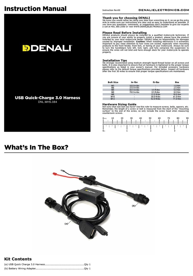
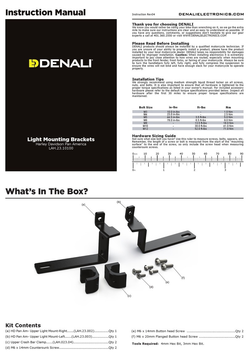
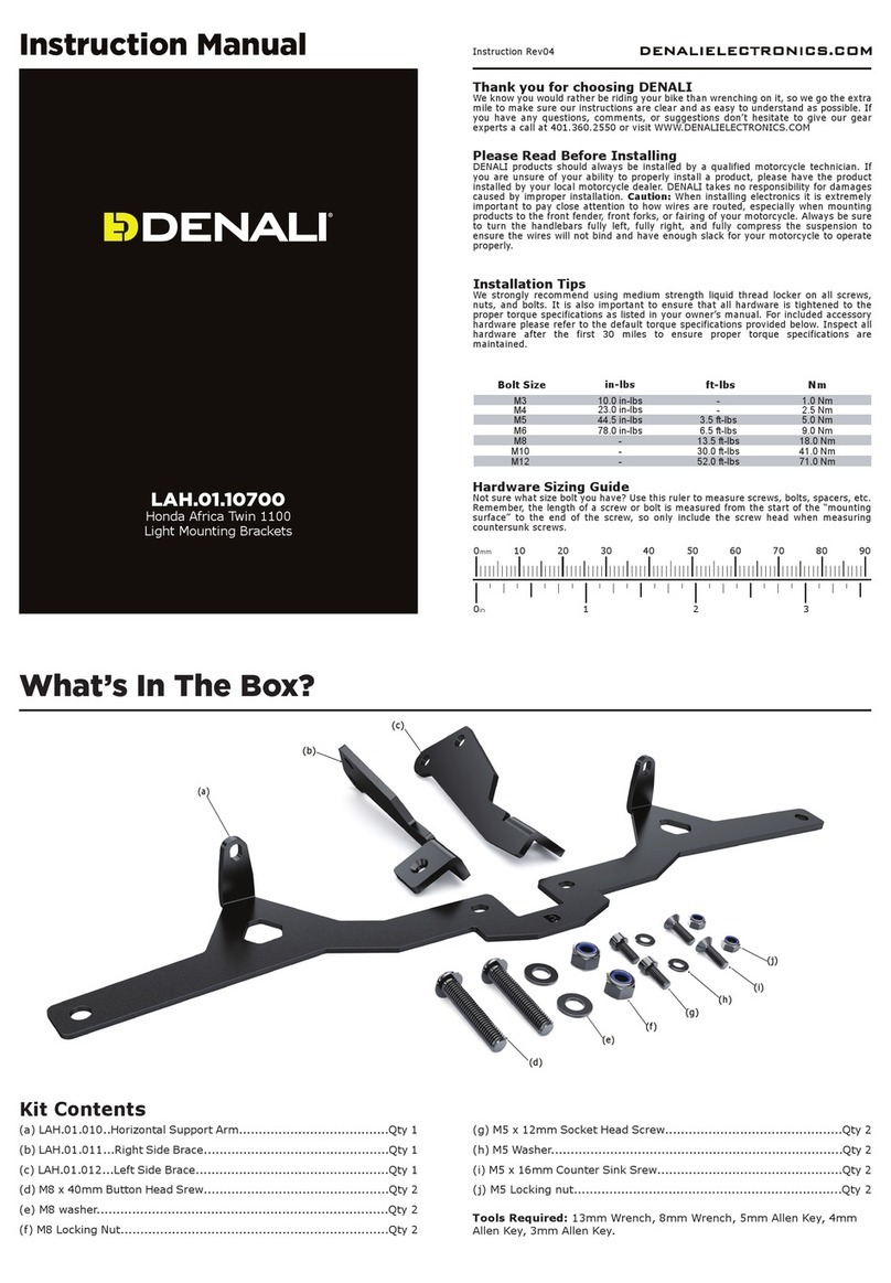
  9. Denali LAH.08.10900 User manual

Denali LAH.08.10900 User manual

Instruction Rev01
0mm 10 20 30 40 50 60 70 80 90
Thank you for choosing DENALI
We know you would rather be riding your bike than wrenching on it, so we go the extra
mile to make sure our instructions are clear and as easy to understand as possible. If
you have any questions, comments, or suggestions don’t hesitate to give our gear
experts a call at 401.360.2550 or visit WWW.DENALIELECTRONICS.COM
Please Read Before Installing
DENALI products should always be installed by a qualified motorcycle technician. If
you are unsure of your ability to properly install a product, please have the product
installed by your local motorcycle dealer. DENALI takes no responsibility for damages
caused by improper installation. Caution: When installing electronics it is extremely
important to pay close attention to how wires are routed, especially when mounting
products to the front fender, front forks, or fairing of your motorcycle. Always be sure
to turn the handlebars fully left, fully right, and fully compress the suspension to
ensure the wires will not bind and have enough slack for your motorcycle to operate
properly.
Installation Tips
We strongly recommend using medium strength liquid thread locker on all screws,
nuts, and bolts. It is also important to ensure that all hardware is tightened to the
proper torque specifications as listed in your owner’s manual. For included accessory
hardware please refer to the default torque specifications provided below. Inspect all
hardware after the first 30 miles to ensure proper torque specifications are
maintained.
Hardware Sizing Guide
Not sure what size bolt you have? Use this ruler to measure screws, bolts, spacers, etc.
Remember, the length of a screw or bolt is measured from the start of the “mounting
surface” to the end of the screw, so only include the screw head when measuring
countersunk screws.
M3 10.0 in-lbs - 1.0 Nm
M4 23.0 in-lbs - 2.5 Nm
M5 44.5 in-lbs 3.5 ft-lbs 5.0 Nm
M6 78.0 in-lbs 6.5 ft-lbs 9.0 Nm
M8 - 13.5 ft-lbs 18.0 Nm
M10 - 30.0 ft-lbs 41.0 Nm
M12 - 52.0 ft-lbs 71.0 Nm
in-lbs
ft-lbs NmBolt Size
0in 1 2 3
What’s In The Box?
DENALIELECTRONICS.COM
LAH.08.10900
Kawasaki KLR 650
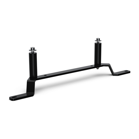
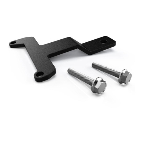
Upper Crash Bar Light Mount
Instruction Manual
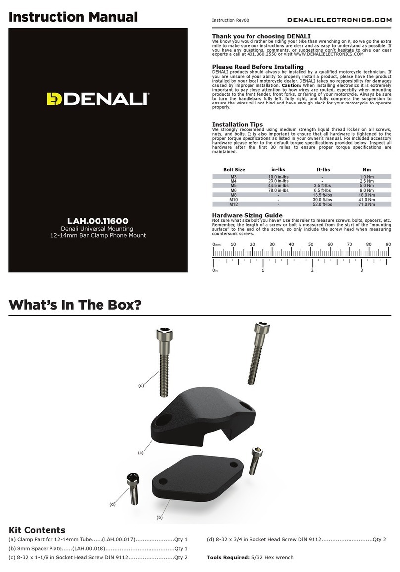
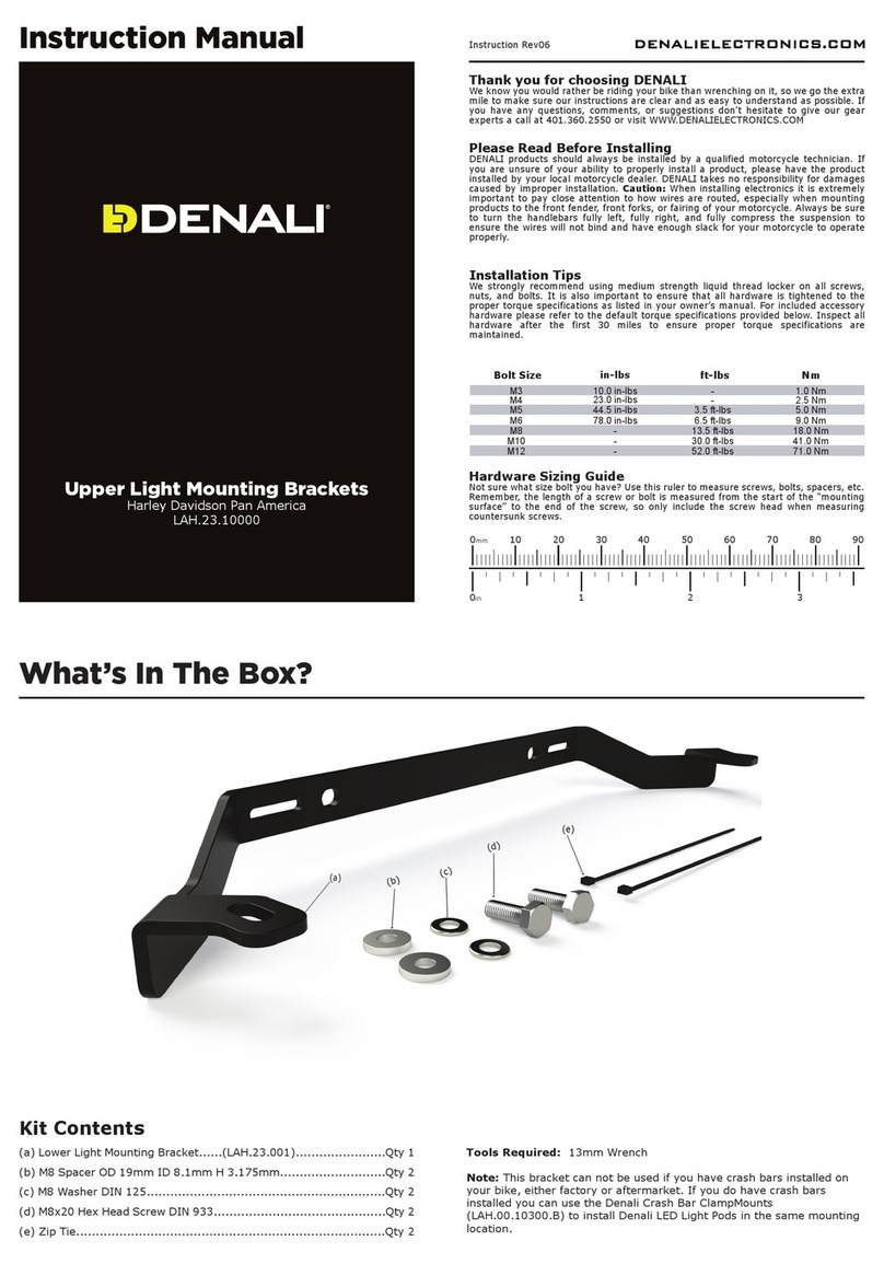
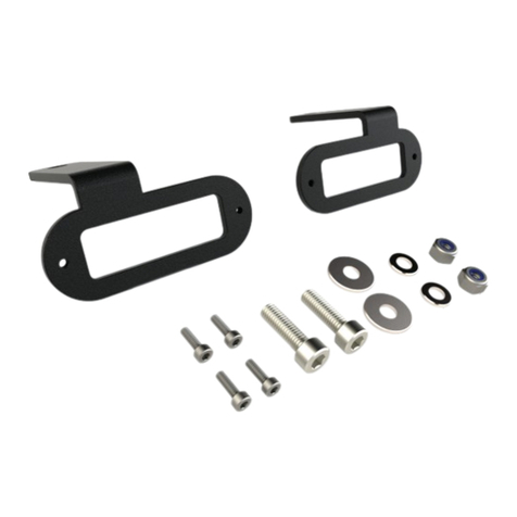
(a) Upper Crash Bar..................................................................Qty 1
(b) M8 Spacer OD:19mm ID:8.4mm Length:15mm.......................Qty 1
(c) M8 x 45mm Flanged Hex Head Screw DIN 6921.......................Qty 1
(d) Crash Bar Clamp Mount Upper...............................................Qty 2
(e) Crash Bar Clamp Mount Lower................................................Qty 2
(f) M5 x 14MM Socket Head Screw DIN 912..................................Qty 4
(g) M8 x 35mm Socket Head Screw DIN 912.................................Qty 2
(h) M8 x 10mm Socket Head Screw DIN 912 ................................Qty 2
Kit Contents
Tools Required: 4mm Hex, 6mm Hex, 12mm Wrench
(a)
(b)
(c)
(h)
(f)
(g)
(e)
(d)
1. Installing The Crash Bar Mount DENALIELECTRONICS.COM
1.1 - Crash Bar Mount Installation
Step One: Remove the front fender and the left & right side covers to gain access to all
of the mounting points. After removing the side covers locate the bottom right factory hex
head screw and remove it.
Step Two: Align the side mounting brackets on the crash bar mount (a) with the left &
right side mounting holes and attach it to the bike using the two M8 x 35mm Socket Head
screws (g). Be careful when bringing the mount up to the bike so as to not scratch the
paint.
Note: Don’t fully tighten the screws yet, leave loose enough to rotate the whole crash bar
mount up.
Step Three: Rotate the Crash Bar (a) up and attach the center bracket using the M8
Spacer (b) between the mounting surface and the top of the bracket and secure it in
place from below with the M8 x 45mm Flanged Hex head Screw (c).
Step Four: Properly tighten all mounting screws and reattach both side covers and
the front fender.
Step Five: Choose the mounting location for your Denali LED Light Pods and assemble
the Crash Bar Clamp Mount components (d,e,f,h). When installing the clamp mount
make sure they end up parallel with the ground and symmetrical with each other.

Other Denali Motorcycle Accessories manuals

Denali ALG.003 User manual

Denali

Denali ALG.003 User manual

Denali HMT.04.10200 User manual

Denali

Denali HMT.04.10200 User manual

Denali D2 User manual

Denali

Denali D2 User manual

Denali DialDim DNL.WHS.22800 User manual

Denali

Denali DialDim DNL.WHS.22800 User manual

Denali SoundBomb DNL.SB.050 User manual

Denali

Denali SoundBomb DNL.SB.050 User manual

Denali T3 User manual

Denali

Denali T3 User manual

Denali T3 User manual

Denali

Denali T3 User manual

Denali HMT.22.10100 User manual

Denali

Denali HMT.22.10100 User manual

Denali DialDim User manual

Denali

Denali DialDim User manual

Denali HMT.08.10300 User manual

Denali

Denali HMT.08.10300 User manual

Denali KLR650 User manual

Denali

Denali KLR650 User manual

Denali HMT.07.11000 User manual

Denali

Denali HMT.07.11000 User manual

Denali LAH.11.10700 User manual

Denali

Denali LAH.11.10700 User manual

Denali HMT.07.11001 User manual

Denali

Denali HMT.07.11001 User manual

Denali LAH.07.11000 User manual

Denali

Denali LAH.07.11000 User manual

Denali LAH.01.10700 User manual

Denali

Denali LAH.01.10700 User manual

Denali LAH.07.11300 User manual

Denali

Denali LAH.07.11300 User manual

Denali LAH.08.10700 User manual

Denali

Denali LAH.08.10700 User manual

Denali DNL.WHS.24200 User manual

Denali

Denali DNL.WHS.24200 User manual

Denali LAH.23.10000 User manual

Denali

Denali LAH.23.10000 User manual

Denali MA11729 User manual

Denali

Denali MA11729 User manual

Denali B6 User manual

Denali

Denali B6 User manual

Denali LAH.04.10700 User manual

Denali

Denali LAH.04.10700 User manual

Denali DialDim DNL.WHS.23900 User manual

Denali

Denali DialDim DNL.WHS.23900 User manual

Popular Motorcycle Accessories manuals by other brands

hepco & becker 5017655 00 01 manual

hepco & becker

hepco & becker 5017655 00 01 manual

Clarke SHW1 User instructions

Clarke

Clarke SHW1 User instructions

Alba Racing pro elite raptor installation instructions

Alba Racing

Alba Racing pro elite raptor installation instructions

Hudora 84201-03 INSTRUCTIONS ON ASSEMBLY AND USE

Hudora

Hudora 84201-03 INSTRUCTIONS ON ASSEMBLY AND USE

JIMS 5832 instructions

JIMS

JIMS 5832 instructions

SUOMY ARMOR User instructions

SUOMY

SUOMY ARMOR User instructions

Bagster Boomerang 7571CB Fitting instructions

Bagster

Bagster Boomerang 7571CB Fitting instructions

hepco & becker 630303 00 01 manual

hepco & becker

hepco & becker 630303 00 01 manual

Tusk X-Small Dry Duffel Bag instructions

Tusk

Tusk X-Small Dry Duffel Bag instructions

SHOEI rf 1000 Instructions for use

SHOEI

SHOEI rf 1000 Instructions for use

hepco & becker 501954 00 01 Mounting instructions

hepco & becker

hepco & becker 501954 00 01 Mounting instructions

SW-Motech GPS.06.525.10200/B Mounting instructions

SW-Motech

SW-Motech GPS.06.525.10200/B Mounting instructions

CATU MO-185 instruction manual

CATU

CATU MO-185 instruction manual

DYNATEK DDK1-10 installation guide

DYNATEK

DYNATEK DDK1-10 installation guide

R&G FI0058BK Fitting instructions

R&G

R&G FI0058BK Fitting instructions

Aketek LIFT-UP AIR Installation, operation and maintenance instructions

Aketek

Aketek LIFT-UP AIR Installation, operation and maintenance instructions

SRC H-CB500X-04-01-AL Installation / Parts List / Bill of Material for Mounting

SRC

SRC H-CB500X-04-01-AL Installation / Parts List / Bill of Material for Mounting

Dakota Digital VHX systems operating manual

Dakota Digital

Dakota Digital VHX systems operating manual

manuals.online logo
manuals.online logoBrands
  • About & Mission
  • Contact us
  • Privacy Policy
  • Terms and Conditions

Copyright 2025 Manuals.Online. All Rights Reserved.