manuals.online logo
Brands
  1. Home
  2. •
  3. Brands
  4. •
  5. Denali
  6. •
  7. Motorcycle Accessories
  8. •
  9. Denali SoundBomb TT-SB.10100.B User manual

Denali SoundBomb TT-SB.10100.B User manual

Instruction Rev02
0mm 10 20 30 40 50 60 70 80 90
Thank you for choosing DENALI
We know you would rather be enjoying your vehicle than wrenching on it, so we go the
extra mile to make sure our instructions are clear and as easy to understand as
possible. If you have any questions, comments, or suggestions don’t hesitate to give
our gear experts a call at 401.360.2550 or visit WWW.DENALIELECTRONICS.COM
Please Read Before Installing
DENALI products should always be installed by a qualified technician. If you are unsure
of your ability to properly install a product, please have the product installed by your
local motorcycle dealer. DENALI takes no responsibility for damages caused by
improper installation. Caution: When installing electronics it is extremely important to
pay close attention to how wires are routed, especially when mounting products to the
front fender, front forks, or fairing of a motorcycle. Always be sure to turn the handle-
bars fully left, fully right, and fully compress the suspension to ensure the wires will
not bind and have enough slack for your motorcycle to operate properly.
Installation Tips
We strongly recommend using medium strength liquid thread locker on all screws,
nuts, and bolts. It is also important to ensure that all hardware is tightened to the
proper torque specifications as listed in your owner’s manual. For included accessory
hardware please refer to the default torque specifications provided below. Inspect all
hardware after the first 30 miles to ensure proper torque specifications are
maintained.
Hardware Sizing Guide
Not sure what size bolt you have? Use this ruler to measure screws, bolts, spacers, etc.
Remember, the length of a screw or bolt is measured from the start of the “mounting
surface” to the end of the screw, so only include the screw head when measuring
countersunk screws.
M3 10.0 in-lbs - 1.0 Nm
M4 23.0 in-lbs - 2.5 Nm
M5 44.5 in-lbs 3.5 ft-lbs 5.0 Nm
M6 78.0 in-lbs 6.5 ft-lbs 9.0 Nm
M8 - 13.5 ft-lbs 18.0 Nm
M10 - 30.0 ft-lbs 41.0 Nm
M12 - 52.0 ft-lbs 71.0 Nm
in-lbs
ft-lbs NmBolt Size
0in 1 2 3
What’s In The Box?
DENALIELECTRONICS.COM
SoundBomb Split Dual-Tone Horn
TT-SB.10100.B
Instruction Manual
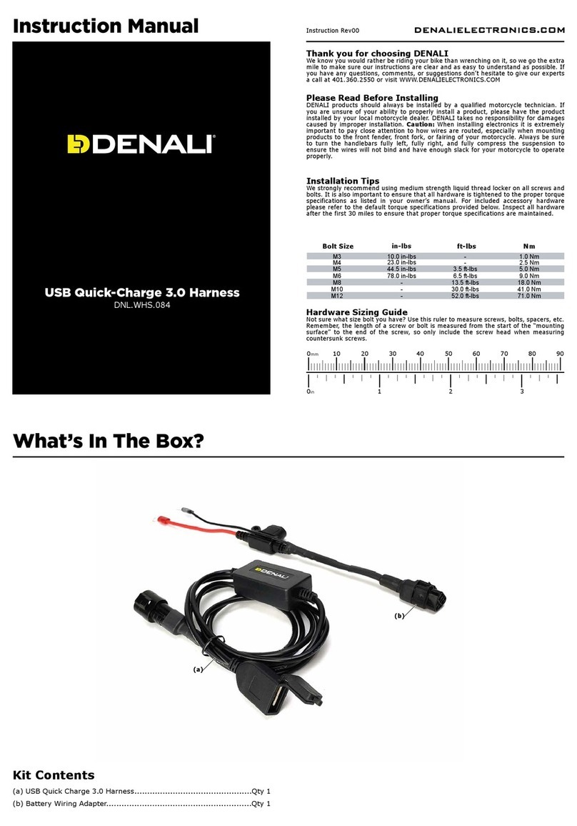
(a) Compressor........................................................................Qty 1
(b) Acoustic Unit......................................................................Qty 1
(c) M8x16 DIN 933...................................................................Qty 1
(d) M8 Nut DIN 985..................................................................Qty 1
(e) M6x20 DIN 933...................................................................Qty 1
(f) Vibration Dampener..............................................................Qty 1
(g) M6 Nut DIN 985..................................................................Qty 1
(h) Air Hose.............................................................................Qty 1
(i) Zip Tie................................................................................Qty 2
Kit Contents
(f)
(g)
(e)
(a)
(b)
(d)
(c)
(i)
(h)
1. Mounting The Horn
1.1 - Mounting The Compressor
Find a suitable mounting location on the vehicle that is protected from road debris and
spray from your tires. Universal and Vehicle-Specific Mounting Brackets are available for
purchase separately.
Step One: Use the M8x16 Bolt (c) and M8 Nut (d) to attach the compressor to the
mounting location.
Note: The compressor should be mounted so that the cylinder is vertical. There should
be no more than a 25 degree variance from the vertical position.
1.2 - Bolt-On Mounting The Acoustic Unit
Step One: Use the M6x20 Bolt (e), Vibration Dampener (f) and M6 Nut (g) to attach the
Acoustic Unit (b) to the mounting location.
Note: The Acoustic Unit can also be mounted using the supplied Zip Ties. Continue to
Section 1.3 for Zip Tie mounting.
DENALIELECTRONICS.COM
90º 115º
65º
-25º +25º
Maximum Allowable Mounting Angle
Compressor
Acoustic Unit
M8x16
M8 Nut
Example Mounting Bracket
M6x20
Vibration
Dampener
M6 Nut
Example Mounting Bracket
1.3 - Zip Tie Mounting The Acoustic Unit
Step One: Slide the Zip Tie (i) through the slots in the Acoustic Unit (b).
Step Two: Tighten the Zip Ties (i) to secure the Acoustic (b) Unit to the vehicle.
1.4 - Connecting The Air Hose
Once you have mounted the Compressor and Acoustic Unit you will need to connect
them using the supplied Air Hose.
Step One: Route the hose (h) through the vehicle to connect the two units. Be sure to
avoid areas of extreme heat such as the engine head or exhaust. The hose is rated for
175° F.
Step Two: Trim the hose to the correct length, then you can push each end of the hose
onto the nipples on the compressor and acoustic unit. It is helpful to heat up the ends
of the hose using a heat gun before
Air Hose
Acoustic Unit
Compressor
Zip Tie
Acoustic Unit
2. Wiring The Horn
2.1 - Wiring
We recommend using the DENALI Plug-N-Play SoundBomb Horn Wiring Kit the make
the install a breeze. (Available for separate purchase, P/N: DNL.ELC.10000) However
the horn can easily be wired using the included 12 Volt 30 Amp Relay (b) and some basic
electrical supplies.
Step One: Connect terminal 85 to the OEM horn harness negative (-) wire.
Step Two: Connect terminal 30 to the OEM horn harness positive (+) wire. Install a
fuse holder in-line.
Step Three: Connect terminal 87 to the positive terminal of the Compressor.
Step Four: Connect a ground wire from the negative (-) terminal of the Compressor to
a ground point on the vehicle or the negative terminal of the battery. Looking at the
front of the horn the negative terminal will be on the left.
Step Five: Connect Terminal 86 to the OEM horn harness positive (+) wire.
Step Six: Install a 30 Amp fuse into the fuse holder.
Note: Place the Relay in an easily accessible location for convenient service in the event
of a faulty relay.
85 86
30
87
+
-
+
-
Note: This drawing is not to scale. Components enlarged for illustration purposes only.
85 87
86 30
Relay Schematic
OEM Horn Harness Negative Wire (-) OEM Horn Harness Positive Wire (+)
Ground Point
(Connect to frame or negative battery terminal)
Battery
Compressor
Relay

Other Denali Motorcycle Accessories manuals

Denali KLR650 User manual

Denali

Denali KLR650 User manual

Denali D2 User manual

Denali

Denali D2 User manual

Denali DialDim DNL.WHS.23900 User manual

Denali

Denali DialDim DNL.WHS.23900 User manual

Denali DialDim User manual

Denali

Denali DialDim User manual

Denali MBK.22.10000 User manual

Denali

Denali MBK.22.10000 User manual

Denali B6 User manual

Denali

Denali B6 User manual

Denali LAH.00.10000.B User manual

Denali

Denali LAH.00.10000.B User manual

Denali DialDim DNL.WHS.22800 User manual

Denali

Denali DialDim DNL.WHS.22800 User manual

Denali MA11729 User manual

Denali

Denali MA11729 User manual

Denali T3 User manual

Denali

Denali T3 User manual

Denali LAH.04.10700 User manual

Denali

Denali LAH.04.10700 User manual

Denali SoundBomb DNL.SB.050 User manual

Denali

Denali SoundBomb DNL.SB.050 User manual

Denali LAH.07.11300 User manual

Denali

Denali LAH.07.11300 User manual

Denali HMT.04.10200 User manual

Denali

Denali HMT.04.10200 User manual

Denali LAH.00.11600 User manual

Denali

Denali LAH.00.11600 User manual

Denali LAH.23.10200 User manual

Denali

Denali LAH.23.10200 User manual

Denali HMT.07.11001 User manual

Denali

Denali HMT.07.11001 User manual

Denali LAH.23.10000 User manual

Denali

Denali LAH.23.10000 User manual

Denali LAH.23.10100 User manual

Denali

Denali LAH.23.10100 User manual

Denali DNL.WHS.12700 User manual

Denali

Denali DNL.WHS.12700 User manual

Denali HMT.07.11000 User manual

Denali

Denali HMT.07.11000 User manual

Denali LAH.01.10700 User manual

Denali

Denali LAH.01.10700 User manual

Denali CANsmart Controller GEN II User manual

Denali

Denali CANsmart Controller GEN II User manual

Denali DNL.WHS.084 User manual

Denali

Denali DNL.WHS.084 User manual

Popular Motorcycle Accessories manuals by other brands

hepco & becker 6547593 00 01 manual

hepco & becker

hepco & becker 6547593 00 01 manual

Dowco Rally Pack Value Series installation instructions

Dowco

Dowco Rally Pack Value Series installation instructions

Crivit 90095 Instructions for use

Crivit

Crivit 90095 Instructions for use

DYNATEK DFCH-3 user manual

DYNATEK

DYNATEK DFCH-3 user manual

Ironton 58043 owner's manual

Ironton

Ironton 58043 owner's manual

OKBABY 929 manual

OKBABY

OKBABY 929 manual

SHIN YO 550-505 quick start guide

SHIN YO

SHIN YO 550-505 quick start guide

ItsImagical neo secura manual

ItsImagical

ItsImagical neo secura manual

Blaupunkt MotoPilot 43 instruction manual

Blaupunkt

Blaupunkt MotoPilot 43 instruction manual

Husqvarna 25103990044 Information

Husqvarna

Husqvarna 25103990044 Information

LSL 377-500SW manual

LSL

LSL 377-500SW manual

PUIG 21340 Mounting instructions

PUIG

PUIG 21340 Mounting instructions

Gazzini 10020889 Instructions & installation

Gazzini

Gazzini 10020889 Instructions & installation

hepco & becker 6504531 00 01 manual

hepco & becker

hepco & becker 6504531 00 01 manual

Cobra 602-2027 manual

Cobra

Cobra 602-2027 manual

Gemini 7854T Installer manual

Gemini

Gemini 7854T Installer manual

DYNATEK DDK3-4 installation guide

DYNATEK

DYNATEK DDK3-4 installation guide

Cardo Systems PACKTALK CUSTOM Pocket guide

Cardo Systems

Cardo Systems PACKTALK CUSTOM Pocket guide

manuals.online logo
manuals.online logoBrands
  • About & Mission
  • Contact us
  • Privacy Policy
  • Terms and Conditions

Copyright 2025 Manuals.Online. All Rights Reserved.