manuals.online logo
Brands
  1. Home
  2. •
  3. Brands
  4. •
  5. DUCATI Performance
  6. •
  7. Motorcycle Accessories
  8. •
  9. DUCATI Performance 96513603B User manual

DUCATI Performance 96513603B User manual

Cod. ISTR - 120 Pag. 1/6
Modelli di riferimento: / Reference Ducati Motorcycles:
DUCATIPERFORMANCE
DUCATI MOTOR HOLDING S.p.A.
I particolari con riferimento cerchiato rappresentano l’accessorio da installare e gli eventuali
componenti di montaggio.
Quelli non cerchiati si riferiscono ai componenti originali che devono essere riutilizzati.
Per una lettura rapida e razionale sono stati impiegati simboli che evidenziano situazioni di
massima attenzione, consigli pratici o semplici informazioni.
Tutte le indicazioni destro o sinistro si riferiscono al senso di marcia del motociclo.
Part nos. that are circled represent the accessory to be installed and possible relevant fittings.
Part nos. that are not circled refer to original parts to be re-used.
For easy and rational reading, this document uses graphic symbols for
highlighting situations in which maximum care is required, practical advice or simple information.
Any right- or left-hand indication refers to the vehicle direction of travel.
Attenzione/Warning
La non osservanza delle istruzioni riportate può creare una situazione di pericolo e causare
gravi lesioni personali e anche la morte.
Failure to follow these instructions might give raise to a dangerous situation and provoke severe
personal injuries or even death.
Importante/Caution
Indica la possibilità di arrecare danno al veicolo e/o ai suoi componenti se le istruzioni
riportate non vengono eseguite.
Failure to follow these instructions might cause damages to the vehicle and/or its components.
Note/Note
Fornisce utili informazioni sull'operazione in corso.
Useful information on the procedure being described.
I particolari riquadrati si riferiscono a particolari da eliminare.
Boxed items must be removed permanently.
I particolari crociati si riferiscono a particolari presenti nel kit ma che non vengono utilizzati.
Crossed out items can be found in the kit but are not used.
Monster 620/800 ie / MS4R
Kit antifurto / Antitheft kit - 96513603B
1 Cablaggio antifurto
2 Guarnizione connettore
3 Centrale di allarme
4 Viti autofilettanti Ø 2,2x9,5
5 Passacavo
6 Vite centrale
7 Guarnizione antivibrante
8 Staffa supporto centrale
9 Dado
10 Microswitch
11 Guaina termorestringente grande
12 Dadi
13 Cablaggio led segnalatore
14 Trasmettitore
15 Anello portachiavi
16 Fascette
17 Staffa supporto microswitch
18 Viti
1 Antitheft system wiring
2 Connector seal
3 Alarm control unit
4 Self-tapping screws Ø 2.2x9.5
5 Fairlead
6 Control unit screws
7 Vibration damping pads
8 Control unit bracket
9Nuts
10 Microswitch
11 Heat-shrink sheath - big
12 Nuts
13 Signaler led wiring
14 Transmitter
15 Key ring
16 Ties
17 Microswitch support bracket
18 Screws
1
8
11
6
17
4
9
7
3
14
513
10 15
2
12
18
16
Cod. ISTR - 120
Pag. 2/6
DUCATIPERFORMANCE
DUCATI MOTOR HOLDING S.p.A.
Note
Read the attached instructions
carefully before proceeding.
How to fit the antitheft kit
Caution
The antitheft system operation is
quite complicated and it is very important
that it operates correctly, it is then
necessary that assembly be made by
qualified personnel such as by any Ducati
dealer.
Warning
Perform the procedure with the
engine stopped.
Support the motorcycle adequately, using a
service stand.
Caution
Check that all components are clean
and in perfect condition before installation.
Take any precaution necessary in order to
avoid damages to nearby surfaces.
Take the antitheft system wiring (1) from
the kit, remove cap (A) from inside the
connector with a screwdriver.
Take the seal (2) from the kit and fit it to
connector (1A) of wiring (1).
Take the control unit (3) from the kit, insert
connector (B) and route cable (C) inside the
suitable recess on connector shell (1A) of
wiring (1).
Take no.6 screws (4) and fairlead (5) from
the kit. Position connector shell (1A) of
wiring (1) to control unit (3), start the six
screws (4) and tighten without forcing.
Insert fairlead (5) onto cable (C) and fit it in
the relevant seat on the shell (1A) with the
help of a screwdriver.
Take no. 2 screws (6) and no. 2 pads (7)
from the kit. Insert screws (6) on the side of
control unit (3) rear end and fit two pads (7)
with the offset edge toward the control
unit.
1A
21A
B
1
3
1AC
34
5 C
41A 1
6
77
3
Note
Prima di iniziare l’operazione, leggere
attentamente le avvertenze riportate nel
foglio allegato.
Montaggio kit antifurto
Importante
La complessità e l’importanza del
corretto funzionamento del sistema
antifurto, richiedono il montaggio da parte di
personale specializzato, rintracciabile in
qualsiasi centro dealer Ducati.
Attenzione
Eseguire l’operazione con motore
spento.
Sostenere adeguatamente il motociclo,
utilizzando un cavalletto ausiliario.
Importante
Verificare, prima del montaggio, che
tutti i componenti risultino puliti e in
perfetto stato.
Adottare tutte le precauzioni necessarie per
evitare di danneggiare le superfici nelle
vicinanze delle quali si opera.
Prelevare dal kit il cablaggio antifurto (1) e,
con un cacciavite, togliere il tappo (A)
dall’interno del connettore.
Prelevare dal kit la guarnizione (2) e inserirla
nel connettore (1A) del cablaggio (1).
Prelevare dal kit la centrale (3), inserirvi il
connettore (B) e far passare il cavo (C)
all’interno dell’apposito incavo ricavato sul
guscio connettore (1A) del cablaggio (1).
Prelevare dal kit n.6 viti (4) e il passacavo (5).
Posizionare il guscio connettore (1A) del
cablaggio (1) sulla centrale (3), impuntare le
sei viti (4) e serrarle senza forzare. Inserire
sul cavo (C) il passacavo (5) e incastrarlo
nell’apposita sede sul guscio (1A) con l’aiuto
di un cacciavite.
Prelevare dal kit n.2 viti (6) e n.2 guarnizioni
(7). Inserire lateralmente le viti (6) sulla parte
posteriore della centrale (3) e montarvi le
due guarnizioni (7) con la parte in rilievo
rivolta verso la centrale.
Cod. ISTR - 120 Pag. 3/6
DUCATIPERFORMANCE
DUCATI MOTOR HOLDING S.p.A.
Take the bracket (8) and no. 2 nuts (9).
Position bracket (8) on control unit (3). Fit
and tighten nuts (9).
Take the microswitch (10), the bracket (17),
and no.2 screws (4) from the kit.
Fit microswitch (10) to bracket (17). Fit and
tighten screws (4).
With reference to the owner’s manual
supplied with the bike:
- Remove the seat.
- Remove the rear right side body panel.
- Raise the tank.
Undo the screws on terminals (D) and (E),
always start from the negative one. Release
rubber fastener (F) and remove the battery
(G).
Release regulator fuse support (H) from
battery mount and cut tie retaining the
wiring.
Loosen screw (J) and remove main and
injection relays (W), keep washer (K).
Loosen the four screws (L) and remove
battery mount (L1) together with rubber
pad.
Loosen the two vibration damping pads (L2)
that are close to the air box only.
8
9
3
10
4
17
FE
D
G
H
L1
JL
L
K
W
L2
Prelevare dal kit la staffa (8) e n.2 dadi (9).
Posizionare la staffa (8) sulla centrale (3);
Impuntare e serrare i dadi (9).
Prelevare dal kit il microswitch (10), la staffa
(17), e n. due viti (4).
Posizionare sulla staffa (17) il microswitch
(10); Impuntare e serrare le viti (4).
Facendo riferimento al libretto istruzioni in
dotazione alla moto:
- Rimuovere la sella.
- Rimuovere il fianchetto posteriore destro.
- Sollevare il serbatoio.
Svitare le viti sui morsetti (D) e (E) partendo
sempre da quello negativo. Sganciare il
gancio elastico (F), quindi sfilare la batteria
(G).
Sganciare il supporto fusibile regolatore (H)
dal supporto batteria e tagliare la fascetta
che vincola il suo cablaggio. Rimuovere i
relè (W) principale e iniezione svitando la
vite (J) e recuperando la rondella (K). Svitare
le quattro viti (L) e rimuovere il supporto (L1)
batteria insieme al tappeto in gomma.
Svitare i soli due antivibranti (L2) vicini alla
scatola filtro.
Cod. ISTR - 120 Pag. 4/6
DUCATIPERFORMANCE
DUCATI MOTOR HOLDING S.p.A.
Fit previously assembled control unit (3) to
battery mount. Fit and tighten the two
vibration damping pads (L2).
Refit the battery mount (L1), fit and tighten
the screws (L). Fix regulator fuse support
(H) to battery mount slot as shown. Loosen
only screw (L) (see picture) securing battery
mount.
Route the wiring as shown in the diagram.
Every connector is numbered in order to
identify every pin to be connected while
installing the kit.
Take no. 2 screws (18) and no. 2 nuts (12)
from the Kit.
Fit previously assembled bracket (17) to
battery mount. Fit screws (18) onto nuts
(12) and tighten. Connect the two faston
connectors of microswitch wiring (M) to the
main wiring harness faston connectors as
indicated: (M1) to (1B) and (M2) to (1C).
Take the two sheaths (11) from the kit.
Disconnect socket (N) from plug (O)
connecting ignition lock and insert a sheath
(11) at both ends. Connect plug (1D) to
socket (N) and plug (O) to socket (1E).
Center the sheaths on the connectors just
attached and heat them with an industrial
heater in order to make the sheaths stick to
the connectors and make them waterproof.
Caution
It is absolutely forbidden to use free
flames or lighters because they do not
ensure a smooth heat-shrinking of the
sheath.
L2
3
L
L1
L
H
1I 1H
1A
1B 1C 1R 1L
1D
1E 1P 1F
1M
1Q 1G
1O 1N
17
M
18
12
M1
1B
M2 1C
1
N
11
O
1D 1E 11
Posizionare il gruppo della centrale (3),
precedentemente montato, sul supporto
batteria. Impuntare e serrare i due
antivibranti (L2).
Rimontare il supporto batteria (L1)
impuntando e serrando le viti (L).
Agganciare il supporto fusibile regolatore
(H) nell’asola del supporto batteria indicato
in foto. Svitare la sola vite (L) di fissaggio
supporto batteria indicata in foto.
Disporre il cablaggio seguendo il disegno.
Ogni connettore è stato numerato al fine di
identificare ogni presa che andremo a
collegare man mano che proseguiremo
nell’installazione del kit.
Prelevare dal Kit n. due viti (18) e n. due dadi
(12).
Posizionare la staffa (17), precedentemente
montata, sul supporto batteria. Impuntare le
viti (18) sui dadi (12) e serrarli. Collegare i
due faston del cablaggio (M) del
microswitch nei faston del cablaggio
principale rispettivamente: (M1) con (1B) e
(M2) con (1C).
Prelevare dal kit due guaine (11). Scollegare
tra di loro la presa (N) dalla spina (O) di
collegamento blocco chiave e inserire una
guaina (11) in ognuno. Inserire la spina (1D)
nella presa (N) e la spina (O) nella presa (1E).
Centrare le guaine sui connettori appena
collegati e scaldarli con un Phon industriale
al fine di far aderire le guaine sui connettori
e renderli praticamente impermeabili.
Importante
E’ tassativamente vietato utilizzare
fiamme libere o accendini i quali non
permettono una termorestringenza
uniforme.
Cod. ISTR - 120 Pag. 5/6
DUCATIPERFORMANCE
DUCATI MOTOR HOLDING S.p.A.
Disconnect socket (P) from plug (Q)
connecting side stand switch. Connect plug
(1F) to socket (P) and plug (Q) to socket
(1G).
Take the two sheaths (11) from the kit.
Disconnect socket (R) from plug (S)
connecting starter motor solenoid contactor
and insert a sheath (11) at both ends.
Connect plug (1H) to socket (R) and plug (S)
to socket (1I). Center the sheaths on the
connectors just attached and heat them
with an industrial heater in order to make
the sheaths stick to the connectors and
make them waterproof.
Caution
It is absolutely forbidden to use free
flames or lighters because they do not
ensure a smooth heat-shrinking of the
sheath.
Loosen screw (U). Fit earth eyelet (1R) at
the screw threaded hole now free. Start
again screw (U) and tighten it.
Disconnect socket (V) from plug (Z)
connecting tail light wiring. Connect plug
(1L) to socket (V) and plug (Z) to socket
(1M).
Fit washer (K) onto screw (J) and refit relay
support (W).
1F
P1G Q
T
S
11
1I
1H
R
11
U1L
2
1M
1L V
JW
K
Scollegare tra di loro la presa (P) dalla spina
(Q) di collegamento interruttore cavalletto.
Inserire la spina (1F) nella presa (P) e la spina
(Q) nella presa (1G).
Prelevare dal kit due guaine (11). Scollegare
tra di loro la presa (R) dalla spina (S) di
collegamento teleruttore motorino
avviamento e inserire una guaina (11) in
ognuno. Inserire la spina (1H) nella presa (R)
e la spina (S) nella presa (1I). Centrare le
guaine sui connettori appena collegati e
scaldarli con un Phon industriale al fine di far
aderire le guaine sui connettori e renderli
praticamente impermeabili.
Importante
E’ tassativamente vietato utilizzare
fiamme libere o accendini i quali non
permettono una termorestringenza
uniforme.
Svitare la vite (U). Posizionare l’occhiello di
massa (1R) in corrispondenza del foro
filettato lasciato libero dalla vite. Impuntare
nuovamente la vite (U) e serrarla.
Scollegare tra di loro la presa (V) dalla spina
(Z) di collegamento cablaggio luci posteriori.
Inserire la spina (1L) nella presa (V) e la spina
(Z) nella presa (1M).
Impuntare la rondella (K) sulla vite (J) e
fissare nuovamente il supporto relais (W).
Cod. ISTR - 120 Pag. 6/6
DUCATIPERFORMANCE
DUCATI MOTOR HOLDING S.p.A.
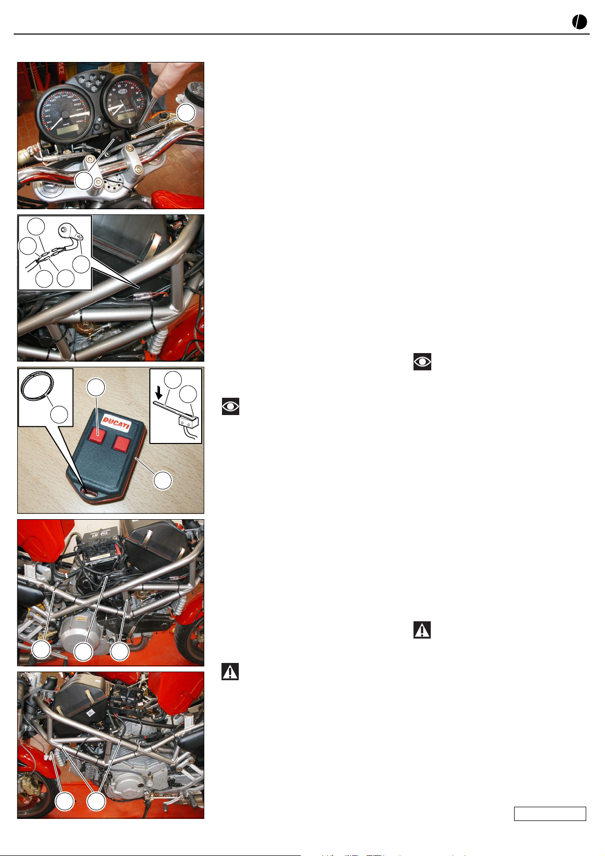
Take the Led Wiring (13) from the kit.
Loosen the right screw (Y) only, securing
instrument panel to front subframe. Fit
bracket with Led (13) under instrument
panel rib, fit and tighten screw (Y). Route
Led wiring so that it follows the cables
going from handlebar to the frame front
right side.
Connect the two faston connectors of Led
wiring (13) to main wiring harness faston
connectors as indicated: (13A) to (1P) and
(13B) to (1Q).
Checks
Take a transmitter (14) and the key ring (15)
from the kit. Fit the ring (15) on transmitter
slot (14) and insert the bike key. Hold down
microswitch (3) rod (3A) and press button
(14A) to enable antitheft system; make sure
it turned on.
Should it not be on, check indicated wiring
connections and make sure they are
properly made.
Note
Antitheft system operation is
explained in the operating instruction
supplied.
Turn handlebar in both directions until the
limit stop and make sure that led wiring (13)
is not too taut.
Take the ties (16) from the kit. Check that
the system works properly and secure the
antitheft system wiring (1) to the frame
using the ties (16), in the areas indicated in
the pictures.
With reference to the owner’s manual
supplied with the bike, refit:
- The battery, following the disassembly
procedure in the reverse order. Check
that contacts are not oxidized and apply
waterproof spray on terminals.
- Rear right side body panel.
- Reposition and secure the tank.
- Refit the seat.
Warning
The Engine Control Unit might store a
starter error that can be detected with the
help of the Mathesis tester.
Y
13
1Q
1P
13
13A
13B
3A
15
14A 3
14
16 116
116
Prelevare dal kit il Cablaggio Led (13).
Svitare la sola vite destra (Y) di fissaggio
cruscotto al telaietto anteriore
portastrumenti. Inserire sotto la nervatura
del cruscotto la staffa con Led (13),
impuntare e serrare la vite (Y). Disporre il
cablaggio del Led in modo che segua i cavi
che dal manubrio scendono fino a giungere
al lato destro, anteriore del telaio.
Collegare i due faston del cablaggio (13) del
Led segnalatore nei faston del cablaggio
principale rispettivamente: (13A) con (1P) e
(13B) con (1Q).
Verifiche
Prelevare dal kit un trasmettitore (14) e
l’anello portachiavi (15). Montare l’anello
(15) sull’asola del trasmettitore (14) e
applicarvi la chiave della moto. Tenendo
premuta l’astina (3A) del microswitch (3)
premere il pulsante (14A) di accensione
antufurto e assicurarsi che l’impianto entri
in funzione.
Nel caso non entri in funzione controllare
tutti i collegamenti elettrici citati e
assicurarsi che siano stati eseguiti a regola
d’ arte.
Note
Le procedure di funzionamento
dell’antifurto sono indicate all’ interno della
confezione.
Ruotare in entrambi i lati e a fine corsa il
manubrio ed assicurarsi che il cablaggio led
(13) non risulti in tensione.
Prelevare dal kit le fascette (16). Constatata
la funzionalità dell’impianto procedere al
fissaggio del cablaggio antifurto (1) al telaio,
nelle zone indicate dalle foto, utilizzando le
fascette (16).
Facendo riferimento al libretto istruzioni in
dotazione alla moto rimontare:
- La batteria con sequenza inversa rispetto
alla rimozione. Verificare che i contatti
non siano ossidati e applicare spray
idrorepellente sui morsetti.
- Il fianchetto posteriore destro.
- Abbassare e agganciare il serbatoio.
- Rimontare la sella.
Attenzione
Può accadere che la centralina di
iniezione della moto registri in memoria un
errore di starter rilevabile con il sistema di
diagnosi Mathesis.
06DE1869A

Other DUCATI Performance Motorcycle Accessories manuals

DUCATI Performance 96780551A User manual

DUCATI Performance

DUCATI Performance 96780551A User manual

DUCATI Performance Superbike 959 User manual

DUCATI Performance

DUCATI Performance Superbike 959 User manual

DUCATI Performance 97180791AA User manual

DUCATI Performance

DUCATI Performance 97180791AA User manual

DUCATI Performance 96681144AA User manual

DUCATI Performance

DUCATI Performance 96681144AA User manual

DUCATI Performance 96981321AA User manual

DUCATI Performance

DUCATI Performance 96981321AA User manual

DUCATI Performance ISTR-1083/01 User manual

DUCATI Performance

DUCATI Performance ISTR-1083/01 User manual

DUCATI Performance 97480171A User manual

DUCATI Performance

DUCATI Performance 97480171A User manual

DUCATI Performance 96780231C User manual

DUCATI Performance

DUCATI Performance 96780231C User manual

DUCATI Performance 96680702A User manual

DUCATI Performance

DUCATI Performance 96680702A User manual

DUCATI Performance 97480161A User manual

DUCATI Performance

DUCATI Performance 97480161A User manual

DUCATI Performance 96880541AA User manual

DUCATI Performance

DUCATI Performance 96880541AA User manual

DUCATI Performance 96680702A User manual

DUCATI Performance

DUCATI Performance 96680702A User manual

DUCATI Performance 96981261AA User manual

DUCATI Performance

DUCATI Performance 96981261AA User manual

DUCATI Performance 96781310B User manual

DUCATI Performance

DUCATI Performance 96781310B User manual

DUCATI Performance 96981461AA User manual

DUCATI Performance

DUCATI Performance 96981461AA User manual

DUCATI Performance 97180821AA User manual

DUCATI Performance

DUCATI Performance 97180821AA User manual

DUCATI Performance 96780231C User manual

DUCATI Performance

DUCATI Performance 96780231C User manual

DUCATI Performance 96681011AA User manual

DUCATI Performance

DUCATI Performance 96681011AA User manual

DUCATI Performance 96880921AA User manual

DUCATI Performance

DUCATI Performance 96880921AA User manual

DUCATI Performance 96781421A User manual

DUCATI Performance

DUCATI Performance 96781421A User manual

DUCATI Performance 96780655A User manual

DUCATI Performance

DUCATI Performance 96780655A User manual

DUCATI Performance 97380182A User manual

DUCATI Performance

DUCATI Performance 97380182A User manual

DUCATI Performance 96780851A User manual

DUCATI Performance

DUCATI Performance 96780851A User manual

DUCATI Performance 96680572A User manual

DUCATI Performance

DUCATI Performance 96680572A User manual

Popular Motorcycle Accessories manuals by other brands

SRC H-AFT17-04-01-AL quick start guide

SRC

SRC H-AFT17-04-01-AL quick start guide

Shad H0CB11ST owner's manual

Shad

Shad H0CB11ST owner's manual

SRC H-ADV150-01-01-SL Installation

SRC

SRC H-ADV150-01-01-SL Installation

LSL ZGT40A FITTING INSTRUCTION

LSL

LSL ZGT40A FITTING INSTRUCTION

Shad NADSA TOPMASTER Y0VR33ST quick start guide

Shad

Shad NADSA TOPMASTER Y0VR33ST quick start guide

Acewell MD-052-2 Series user manual

Acewell

Acewell MD-052-2 Series user manual

PUIG 3173 Mounting instructions

PUIG

PUIG 3173 Mounting instructions

NZI Helmets Street Track owner's manual

NZI Helmets

NZI Helmets Street Track owner's manual

PerTronix Compu-Fire 53730 installation instructions

PerTronix

PerTronix Compu-Fire 53730 installation instructions

Dynojet Power Commander III ZX10R installation instructions

Dynojet

Dynojet Power Commander III ZX10R installation instructions

LAZER Bayamo user guide

LAZER

LAZER Bayamo user guide

Dynojet Power commander V installation instructions

Dynojet

Dynojet Power commander V installation instructions

Thunderbike Old style manual

Thunderbike

Thunderbike Old style manual

Shad K0ZS11ST quick start guide

Shad

Shad K0ZS11ST quick start guide

CAMP SPPED COMP manual

CAMP

CAMP SPPED COMP manual

Digitsole Warm Series user manual

Digitsole

Digitsole Warm Series user manual

kellermann KH 1000 Mounting instructions

kellermann

kellermann KH 1000 Mounting instructions

LUIMOTO DL1 installation instructions

LUIMOTO

LUIMOTO DL1 installation instructions

manuals.online logo
manuals.online logoBrands
  • About & Mission
  • Contact us
  • Privacy Policy
  • Terms and Conditions

Copyright 2025 Manuals.Online. All Rights Reserved.