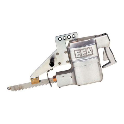
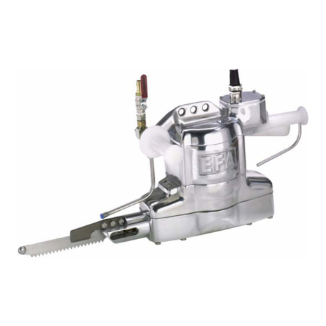
EFA SL24 WB Guide

Ersatzteilliste
Betriebsanleitung
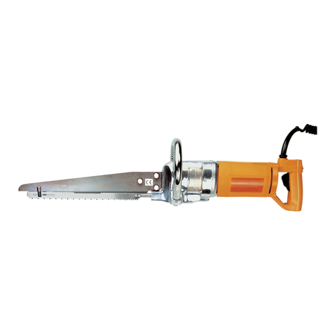
Stichsäge
Typ EFA SL24 WB
Spare Parts List
Instruction Manual
List Englisch page 9

Printed in Federal Republic of Germany 12.2001
Änder
ungen vorbehalten
Copyri
ght by EFA
- 2 -
Bild-Nr.
Ref.-No Stück
p
iece Benennung
Description Bestell-Nr.
Order no. Bestell-Nr.
Order no.
42 V 230 V
Stichsäge EFA SL 24 WB EFA SL 24 WB 110890215 110890205
1 Motor komplett mit 1-45 Motor compl . 1-45 008010589 008009960
1 1 Motorgehäuse Motor housing 001607919 001607919
2 1 Feldpaket kompl. Stator compl. 001607934 001607929
3 2 Linsenblechschraube Lens sheet metal screw 001607917 001607917
4 1 Luftleitscheibe Air washer 001607916 001607916
5 1 Anker Armature 001607933 001607912
6 1 Rillenkugellager Ball bearing 001345301 001345301
7 1 Rillenkugellager Ball bearing 001607915 001607915
7a 1 Scheibe Washer 003009319 003009319
8 1 Ritzel Pinion 003008836 003008836
9 1 Zwischenflansch Intermediate flange 003008830 003008830
9a 1 Zwischenscheibe Intermediate disk 003009958 003009958
10 2 Hülse Socket 001606701 001606701
11
1
Lagerschild vst. mit Nr.
10,12, 12a End shield compl .with no.
10.12.12a 007009959 007009959
12 4 Stiftschraube Stud bolt 001326209 001326209
12a 1 Nadelhülse Needle bush 001342705 001342705
13 8 Linsenblechschraube Lens sheet metal screw 001327507 001327507
14 2 Kohlehalter vst. Carbon brush holder 001607935 001607910
15 2 Kohlebürste Carbon brush 001607911 001607911
16 2 Rundschnurring Toroidal ring 001317734 001317734
17 2 Kohlehalterdeckel Carbon brush cover 003008856 003008856
18 2 Linsenblechschraube Lens sheet metal screw 001607920 001607920
19 1 Zwischenflansch Intermediate flange 003008829 003008829
20 1 Elektronik, Electronic 003010604 003010168
21 1 Handgriff Handle 003009071 003009071
22 1 Kabel mit Stecker Cable with plug 001601746 001607931
23 1 Kabelschutz Protective covering of cable ------------ 001606339
24 1 Verschraubung screw 001325516 ------------
24 1 Druckschraube Pressure screw ------------ 001606711
25 1 Scheibe Disk ------------ 001606712
26 1 Dichtring Packing ring ------------ 001606713
27 1 Kabelschelle Cable clamp ------------ 001606338
28 2 Linsenblechschraube Lens. sheet metal screw ------------ 001327512
29 1 Dichtung Seal 001606721 001606721
30 1 Abdeckkape Cover cap 007001867 007001867
31 1 Schalter Switch 001601213 001601203
33 1 Linsenblechschraube metal screw 001327503 001327502
40 5 Kabelbinder Cable tie 001371912 001371912
41 1 Kondensator Condenser 001607924 001607924

Printed in Federal Republic of Germany 12.2001 Änderungen vorbehalten Copyright by EFA
- 3 -
41a 1 Sicherungseinheit Protection unit 003009518 ------------
41b 1 Halter plate 003008476 ------------
43 1 Handgriffdeckel Handle cover 001606720 001606720
44 3 Linsenblechschraube Lens sheet metal screw 001327511 001327511
45 3 Scheibe Disk 001318210 001318210
9a´
41a 41b

Printed in Federal Republic of Germany 12.2001 Änderungen vorbehalten Copyright by EFA
- 4 -
Bild-Nr.
Ref-No. Stück
piece Benennung
Description
Bestell-Nr.
Order no.
Getriebekopf kpl.Nr. 60-76, 78-97
Gear head, complete
no. 60-76,78-97 008009961
60 1 Nadelhülse Needle bush 001342723
61 3 Schmiernippel Lubricant 001305802
62 1 Stirnrad Spur gear 003009957
63 1 Paßfeder Adjusting spring 001305414
64 2 Sechskantmutter Hexagon nut 001304203
65 1 Fettkammerblech Grease chamber plate 003006023
66 2 Zylinderschraube m.I.-Skt Cheese head screw 001320236
67 1 Sicherungsring Circlip 001317511
68 1 Paßscheibe Shim ring 001315215
69 1 Schrägkugellager Angular ball bearing 001340503
50 1 Taumelglocke Wobble bell 003006026
71 1 Schrägkugellager Angular ball bearing 001340502
72 8 Federring spring ring 001317001
73 4 Sechskantschraube Hexagon screw 001325901
74 1 Sicherungsring Circlip 001317509
75 1 Handgriff Handle 003006030
76 1 Taumelwelle Wobble shaft 003006027
77
1
1 Sägeblatt 200mm *Standard
Sägeblatt 300mm Saw blade 200 mm *standard
Saw blade 300 mm 003006035
003006036
78 4 Senkschraube Flat head screw 001326512
79 1 Dichtung Sealing 003006032
80 1 Dichtring Sealing ring 003006031
81 1 Dichtring Sealing ring 001344106
82 2 Selbsts. Sechskantmutter Self adjusting hexagon nut 001304503
83 1 Spannplatte Z-clamp 003006034
84 2 Sechskantschraube Hexagon screw 001325907
85 1 Hubspindel Lifting spindle 003006021
86 1 Deckel vst. mit Nr. 80 Cover complete with No. 80 007006290

Printed in Federal Republic of Germany 12.2001 Änderungen vorbehalten Copyright by EFA
- 5 -
Bild-Nr .
Ref-No Stück
piece Benennung
Descritpion
Bestell-Nr
Order no.
87
88 2
4 Flanschlager vst. mit Nr. 61
Sechskantschraube Flange bear.compl with no. 61
Hexagon screw 007006292
001325912
89
90 4
1 Federring
Gelenkbolzen spring ring
Hinge pin 001317002
003006024
91
92
93
94
95
1
1
1
2
1
Gelenklager
Pendelhülse vst. mit Nr. 81
Sicherungsring
Sprengring
Pleuel
Pivot bearing
Floating adapter with no. 81
Circlip
Retaining ring
Connecting rod
001345202
007006291
001312409
001313916
003006020
96
97
98
1
1
4
Bügelöse
Gehäuse vst. mit Nr. 61
Zylinderschraube m. I-Skt.
Clip release
Housing cpl.with no. 61
Cylinder screw
002000185
007006289
001326023
Zubehör, im Lieferumfang enthalten
Accessories.incl. in tue scope of
supplies:
1
Ring- Gabelschlüssel
Ring open-end wrench
001367804
A
B
1
1
1
1
1
1
Sonderzubehör
Federzug
Werkzeugsatz (A-B)
Montagedorn
Abziehwerkzeug
Fettpresse
Tube Spezialfett 0,8 kg
Special accessories
Spring balancer
Set of tool (A-B)
Mounting rod
Dismantling tool
Grease gun
Tube of special grease
001620030
007899667
003006607
007006606
001365403
001365613
001603511
5. Technische Daten
Spannung 42 V ~ Spannung 230 V ~
Motorleistung 1020 W Motorleistung 1020 W
Sägeblatt 200 mm
(
Standardausführun
g)
Sägeblatt 200 mm
(
Standardausführun
g)
Sägeblatt 300 mm Sägeblatt 300 mm
Schnitte 9000 / min Schnitte 9000 / min
Hublänge 25 mm Hublänge 25 mm
Gewicht 6,4 kg
Gewicht 6,4 kg
5. Technical Data
Voltage 42 V
Voltage 230 V
Motor Output 1020 W Motor Output 1020 W
Saw blade 200 mm (Standard) Saw blade 200 mm (Standard)
Sawblade 300 mm Sawblade 300 mm
Cutting 9000/min Cutting 9000/min
Stroke length 25 mm Stroke length 25 mm
Weight 6,4 kg
Weight 6,4 kg

Printed in Federal Republic of Germany 12.2001 Änderungen vorbehalten Copyright by EFA
- 6 -
Achtung!
Nur gültig für Reparatur-Fachpersonal.
Laie darf keine Reparatur ausführen,
sonst Unfallgefahr!
1. Anschluß und Inbetriebnahme
Die Stichsäge muß entsprechend den Vorschriften von VDE und der Örtlichen EVU durch
einen anerkannten Elektrotechniker angeschlossen werden. Vor dem Einsatz sind Betriebsdaten
von Betriebsnetz und Gerät auf Übereinstimmung zu prüfen. Die Stichsäge ist serienmäßig mit 4
m Kabel und einer Steckvorrichtung versehen.
2. Bestimmungsgemäßer Einsatz
2.1 Einsatzgebiet
Für den rationellen Schlacht- und Zerlegebetrieb, zum Zerlegen von Rindern, Kälbern und
Schweinen. Einsatz ´in Mittel- und Großbetrieben. Besonders vorteilhaft für Abvierteln von
Rinderhälften - Abtrennen des Lappen vom Hinterviertel -und Abvierteln von ganzen Kälbern.
2.2 Arbeitsganq
- Stichsäge einschalten
- im laufenden Zustand in Tierkörper führen
- im laufenden Zustand Stichsäge aus Tierkörper nehmen und dann erst
abschalten.
2.3 Betriebssicherheit
Zur sicheren Handhabung Führung) sollte die Stichsäge an einem Federzug aufgehängt sein.
Maschine an beiden Handgriffen (33+75) führen. Im eingeschalteten Zustand besonders
umsichtig handeln. Sägeblatt (77) nicht verkannten oder verklemmen. Maschine vor
Reinigungs-, Wartungs- und Reparaturarbeiten vom Stromnetz trennen.
Die Luftschlitze beiderseitig am Motor sind von Schmutz freizuhalten - der Motor darf nicht in
Wasser getaucht werden, da sonst Unfallgefahr durch elektrische Einwirkung !
Die Stichsäge ist nach Schutzklasse II Schutzart IP 24 (Spritzwasser geschützt) gebaut.
Das Motorgehäuse (1) darf (z.B. zum Anbringen von Schildern) nicht angebohrt
werden, da hierdurch die Wirksamkeit der Schutzisolierung aufgehoben werden könnte.
Handgeführte elektrische Maschinen müssen zur Erhöhung der Sicherheit mit einem
Personenschutzstecker (Fi- Schutzschalter 30 mA) ausgerüstet werden
(Bestell-Nr. 001 603 511). Maschinen mit Kleinspannung sind davon ausgenommen.
Achtung!
Bei Werkzeugwechsel und vor Reinigungs-
Wartungs- oder Reparaturarbeiten
Maschine vom Netzbetrieb trennen
3. Wartung
Maschine vom Netz trennen.
Nach dem Einsatz muß die Stichsäge einwandfrei gereinigt werden, damit diese den
hygienischen Anforderungen genügt.
Die Dichtung (49) am Handgriff und die Schalterabdeckkappe (42) sind bei jeder
Wartung auf Funktion zu prüfen.
Die Maschine muß alle 50 Betriebsstunden durch die Schmiernippel (61) mit 3
Stößen aus der Fettpresse gewartet werden.
Schmiermittel: EFA-Spezialfett (0,8 kg), Bestell-Nr. 001 365 613,

Printed in Federal Republic of Germany 12.2001 Änderungen vorbehalten Copyright by EFA
- 7 -
Sägeblattwechsel:
Stecker aus Steckdose ziehen, beide Skt.-Muttern (82) mit Ring-Gabelschlüssel
abschrauben und Sechskantschrauben (84) mit Spannplatte (83) und Sägeblatt (77)
abnehmen. Die Montage erfolgt in umgekehrter Reihenfolge.
4. Kohlebürstenwechsel
4.1 Abschaltautomatik
Wenn die Kohlebürsten (28) abgenutzt sind, unterbricht die Abschaltautomatik die
Stromzufuhr und die Maschine bleibt stehen. Dadurch entfällt die laufende Kontrolle
der Kohlebürsten (28) und der Kollektor des Ankers (15) kann nicht durch die
Bürstenfedern beschädigt werden,
4.2 Hinweise
ACHTUNG! Zuerst den Stecker aus der Steckdose ziehen. Die Kohlebürsten (28)
müssen paarweise ausgetauscht werden.
6. Montageanleitung
Maschine von Betriebsnetz trennen,
6.1 Demontage Getriebekopf kpl.
6.1.1 Skt.-Mutter (82) ausschrauben. Spannplatte (83) und Sägeblatt (77)
abnehmen. Schrauben (98+73) ausschrauben, Getriebekopf kpl. von Motor kpl.
trennen und Deckel vst. (86) abnehmen.
6.1.2 Taumelwelle (76) an Vierkant halten und Skt.-Mutter (64) auf der Motorseite
ausschrauben (SW 19, Linksgewinde). Stirnrad (62) mittels Abziehwerkzeug (B)
abziehen. Dazu die beiden äußeren Zyl.-Schrauben in Stirnrad (62), und die
mittlere Zyl.-Schraube gegen den Lagerzapfen einschrauben.
6.1.3 Zyl.-Schrauben (66), Fettkammerblech (65) und Sicherungsring (93)
demontieren.
6.1.4 Schraube M6 in Pleuel (95) schrauben, mit Gummihammer abwechselnd auf
beide Seiten des Pleuels (95) leichte Schläge ausführen und Pleuel (95)
mittels Schraube abziehen.
6.1.5 Sprengringe (94) mit spitzem Gegenstand demontieren. Gelenklager (91) und
Nadelhülse (60) mit Montagedorn (A) auspressen.
6.1.6 Senkschrauben (78) ausschrauben und Flanschlager (87) ausbauen. Paßfeder
(63) demontieren. Taumelwelle (76) verbunden mit Hubspindel (85) und
Pendelhülse (92) aus Gehäuse (97) auspressen.
6.1.7 Sicherungsring (67) demontieren und .Schrägkugellager (69) samt Paßscheibe
(68) mittels Montagedorn (A) auspressen
6.1.8 Skt.-Mutter (64) ausschrauben (Linksgewinde) und Sicherungsring (74)
demontieren. Taumelwelle (76) aus Schrägkugellager (71) und dieses mittels
Montagedorn (A) auspressen. Dichtringe (80+81) mit spitzem Gegenstand
demontieren und gemeinsam austauschen.
6.2 Demontage Motor kpl.

Printed in Federal Republic of Germany 12.2001 Änderungen vorbehalten Copyright by EFA
- 8 -
Der Motor kpl. ist mit werkstattüblichen Werkzeugen zu zerlegen. Vor dem Ausbau des
Ankers (5 ) sind unbedingt zuerst die 2 x Deckel (17) undKohlebürsten ( 15) auszubauen, um
eine Zerstörung derselben zu vermeiden.
6.4 Montage Getriebekopf
- erfolgt in umgekehrter Reihenfolge von P. 6.1
Hinweis:
Dichtringe (80+81) von Hand einbauen. Schrägkugellager (71+69), Gelenklager (91)
und Nadelhülse (60) mit Montagedorn (A) einpressen.
Taumelglocke (70), Pendelhülse (92) und Hubspindel (85) zusammengesteckt in
Gehäuse vst. (97) einbauen.
Anzugsmomente:
Skt.-Mutter (64) = 50,0 Nm
Senkschraube (78) = 3,0 Nm
Zyl.-Schraube (66) = 1,5 Nm
Skt.-Schraube (73) = 3,0 Nm
Zyl.-Schraube (98) = 4,5 Nm
Skt.-Mutter (82) = 6,5 Nm
Skt.-Schraube (88) = 6,5 Nm
6.5 Montage Motor kpl.
-erfolgt in umgekehrter Reihenfolge von P. 6.2
Stellung der Tellerfedern (31) beachten (siehe Expl. Zn.). 2 x Deckel (17) und
Kohlebürsten (15) erst nach Montage des Ankers ( 5) einbauen

Printed in Federal Republic of Germany 12.2001 Änderungen vorbehalten Copyright by EFA
- 9 -
Instruction Manual EFA SL24 WB
Warning!
Only valid for specialists in repairs
Laymen should not carry out any repairs
otherwise danger of accidents
1. Connection and Initial Operation
The saw must be connected by a reputable electrician in accordance with the regulations of
the VDE and the local EVU. Before use, the operating data, power supply and works
equipment must be checked for conformity. The saw is equipped with a 4 m cable, plug and
socket as Standard.
2. Intended Use
2.1 Field of Application
For efficient use in the slaughtering and carving trade - for carving up cattle, calves and pigs.
Application in middle-sized and large-sized companies. In particular, advantageous for
quartering cattle halves - removal of thin flank from hindquarter and quartering of calves.
2.2 Operation
• Switch on saw
• Whilst saw is running place on carcass
• Whilst still running remove the saw from the carcass and then switch off.
2.3 Operational Safety
For safe handling (control), the saw should be suspended by a sprung-tensile force. Hold the
machine with both handles (33 + 75). When the machine is switched on be extremely careful.
Do not twist or jam saw blade. Disconnect machine from the mains before cleaning and
carrying out maintenance and repair work.
The air slit on both sides of the motor must be free from dirt - the motor must not be dipped in
water due to possible electrical dangers!
The saw is constructed in compliance with protection class II, international protection lP 24
(splash proof).
The motor casing (1) should not be drilled into (e.g. when affixing plates), äs the
effectiveness of the protective Isolation could be offset.
Hand held electrical machinery must be equipped with a protection cover (residual current
operated-device circuit breaker 30 mA) to increase safety (order No. 001 603 511). Machines
with extra-low voltage are exempt.

Printed in Federal Republic of Germany 12.2001 Änderungen vorbehalten Copyright by EFA
- 10 -
Warning!
When changing tools and before cleaning
or carrying out maintenance and repair work
disconnect from the mains
3. Maintenance
Disconnect machine from the mains. After use, the saw must be fully rinsed, in order to satisfy
the hygienic requirements.
During every maintenance check, the seal (49) on the handle and switch plate (42) must be
examined to see if they function properly.
Every 50 hour of Operation the machine must be maintained by lubricant (61) and with 3
squirts from the grease gun.
Lubricant: EFA special grease (0.8 kg). Order No. 001 365 613.
Changing of Saw Blades:
Disconnect plug from socket, unscrew both hexagon nuts (82) with ring open-end wrench,
remove hexagon screws (84) and saw blade (77) with Z-clamp (83). Assembly proceeds in
the reverse order.
4. Changing of Carbon Brush
4.1 Automatic Cut Off
If the carbon brushes (28) are worn out, the automatic cut off breaks the power supply and the
machine comes to a standstill. Through this the runnihg control of the carbon brushes (28) is
cancelled and the collector of the armature can not be damaged by the brush spring.
4.2 Note
WARNING! First pull the plug out of the socket. The carbon brushes (28) may only be
changed in pairs.

Printed in Federal Republic of Germany 12.2001 Änderungen vorbehalten Copyright by EFA
- 11 -
6. Assembly Instructions
Disconnect machine from the mains.
6.1 Dismantle complete gear head
6.1.1 Unscrew hexagon nut (82). Remove Z-clamp (83) and saw blade (77). Unscrew screws
(98 + 73), remove complete gear head from complete motor coupling and cover
completely. (86).
6.1.2 Place wobble shaft (76) on shank and unscrew hexagon nut (64) on the motor side, (SW
19, left hand thread). Take out spur gear (62) with dismantling tool (B). As a result both
external cheese head screws are screwed into the spur gear (62) and the middle
cheese heads screws driven home to the bearing Journal.
6.1.3 Dismantle cheese head screw (66), Grease chamber plate (65) and circlip (93).
6.1.4 Drive home screw M6 into connecting rod (95), With rubber mallet lightly hit the
connecting rod (95) alternating from side to side and remove connecting rod (95) by
means of the screws.
6.1.5 Carefully dismantle retaining rings (94). Force out pivot bearing (91) and needle bush
(60) with mounting rod (A).
6.1.6 Unscrew flat head screws (78) and dismount flange bearing (87). Dismantle adjusting
spring (63). Force out wobble shaft connected to lifting spindle (85) and floating adapter
(92) from casing (97):
6.1.7 Dismantle circlip (67), angular ball bearing (69) and all shims (68) by means of mounting
rod (A).
6.1.8 Unscrew hexagon nut (64) (left hand thread) and dismount circlip (74). Via the mounting
rod (A) force out the wobble shaft (76) from the angular ball bearing (71). Carefully
dismantle sealing rings (80 + 81) and replace them together.
6.2 Dismantling of complete motor
The complete motor must be dismantled with Standard workshop tools. Before dismantling
the armatures (5), 2 x cover (17) and carbon brushes (15) must be removed to avoid the
motor from being ruined.
6.4 Assembly of the gear head
Instructions on p. 6.1 are carried out in the reverse order
Note:
Install sealing rings (80 + 81) by hand. Press in angular ball bearing (71 + 69), pivot bearing
(91) and needle bush (60) with mounting rod (A).
Fit together wobble bell (70), floating adapter (92) and lifting spindle (85) and completely
install in casing (97).

Printed in Federal Republic of Germany 12.2001 Änderungen vorbehalten Copyright by EFA
- 12 -
Tightening torque
Hexagon nut (64) = 50.0 Nm
Fiat head screw (78) = 3.0 Nm
Cheese head screw (66) =1.5 Nm
Hexagon screw (73) = 3.0 Nm
Cheese head screw (98) = 4.5 Nm
Hexagon nut (82) = 6.5 Nm
Hexagon screw (88) = 6.5 Nm
6.5 Assembly of complete motor
- Instructions on p. 6.2 are carried out in the reverse order Pay attention when positioning the
disk spring (31), (see example drawing). After mounting the armature (5) install 2 x cover (17)
and carbon brushes (15).
Maybachstrasse 2
D-75433 Maulbronn • Deutschland
Telefon 07043/102-81/82 • Fax 07043/10278
Table of contents
Languages:
Other EFA Saw manuals
Popular Saw manuals by other brands
MasterCraft
MasterCraft Maximum Hawkeye Laser 055-6746-0 owner's manual

Hitachi
Hitachi C 6MEY Handling instructions
Wacker Neuson
Wacker Neuson BFS 1350AL Operator's manual
Craftsman
Craftsman 315.212180 owner's manual
Craftsman
Craftsman 109.22620 Operating and parts manual
GÖLZ
GÖLZ FS125 Operating instructions and parts manual


