Erbe VIO 300 D User manual

2022-0480116-288_V23381
USA
SERVICE MANUAL
VIO®300 D
V 2.1.x
V 2.2.x
V 2.3.x
V 2.7.x
ELECTROSURGERY


SERVICE MANUAL
VIO®300 D

Erbe Elektromedizin GmbH owns these trademarks in the United States: APC, APC 300, AUTO CUT, BICLAMP, ENDO CUT,
ERBE, ERBECRYO, erbe power your performance., ERBEJET, ERBELIFT, ERBOKRYO, FIAPC, FORCED COAG, HYBRIDAPC,
HYBRIDKNIFE, ICC 200, KYRON, NESSY, NESSY Ω, PRECISE APC, PULSED APC, REMODE, SOFT COAG, SWIFT COAG, THERMO
SEAL, TWIN COAG, VIO.
Trademarks®
Erbe USA, Inc. owns these trademarks: CLEVERCAP, ECO2, ERBEFLO, ERBEFLO AeroRinse, THE TRUE BLUE PROBE FOR APC,
THE TRUE BLUE PROBE FOR ARGON PLASMA COAGULATION and the color blue for APC probes.
TrademarksTM
Erbe USA, Inc. uses these trademarks: APC 360° Circumferential Probe, AUTO START, AUTO STOP, BIPOLAR COAG, BIPOLAR
CUT, DRY CUT, dryCUT, EIP, ESM, FORCED APC, forcedAPC, highCUT, POWER PEAK SYSTEM PPS, preciseSECT, PULSED COAG,
PULSED CUT, SPRAY COAG, sprayCOAG.
For an up-to-date list of all Erbe trademarks, please visit www.erbe-med.com/IP.
All rights to this manual, in particular rights of duplication, dissemination and translation, are reserved. No part of this man-
ual may be reproduced in any form (by photocopying, microfilming or other methods) or processed, duplicated or dissem-
inated by the use of electronic systems without the written consent of Erbe Elektromedizin GmbH.
The information contained in this manual may be amended or supplemented without prior notice and represents no obli-
gation on the part of Erbe Elektromedizin GmbH.
The display illustrations in these instructions may deviate from one another depending on the software version. The display
illustrations used in these instructions are generally taken from the latest software version. Display illustrations from older
software versions will only be used if necessary due to service activities; these will be specifically labeled.
Printed by Erbe Elektromedizin
Printed in Germany
Copyright © Erbe Elektromedizin GmbH, Tübingen 2022

5 / 110
Table of Contents
80116-288_V23381
2022-04
Table of Contents
1Safety information . . . . . . . . . . . . . . . . . . . . . . . . . . . . . . . . . . . . . . . 7
Classification of the safety information. . . . . . . . . . . . . . . . . . . . . . . . . . . . . . . . . 7
Meaning of the note . . . . . . . . . . . . . . . . . . . . . . . . . . . . . . . . . . . . . . . . . . . . . . . . 7
Knowledge of the User Manual . . . . . . . . . . . . . . . . . . . . . . . . . . . . . . . . . . . . . . . 7
Protection from the risk of electric shock . . . . . . . . . . . . . . . . . . . . . . . . . . . . . . . 8
Electrostatically sensitive components . . . . . . . . . . . . . . . . . . . . . . . . . . . . . . . . 10
Liability and warranty. . . . . . . . . . . . . . . . . . . . . . . . . . . . . . . . . . . . . . . . . . . . . . 10
2Modifications. . . . . . . . . . . . . . . . . . . . . . . . . . . . . . . . . . . . . . . . . . . 11
From VIO version 2.2.x . . . . . . . . . . . . . . . . . . . . . . . . . . . . . . . . . . . . . . . . . . . . . 11
From VIO version 2.3.x . . . . . . . . . . . . . . . . . . . . . . . . . . . . . . . . . . . . . . . . . . . . . 11
From VIO version 2.7.x . . . . . . . . . . . . . . . . . . . . . . . . . . . . . . . . . . . . . . . . . . . . . 12
3Controls . . . . . . . . . . . . . . . . . . . . . . . . . . . . . . . . . . . . . . . . . . . . . . . 13
Controls at the front . . . . . . . . . . . . . . . . . . . . . . . . . . . . . . . . . . . . . . . . . . . . . . . 13
Controls at the rear. . . . . . . . . . . . . . . . . . . . . . . . . . . . . . . . . . . . . . . . . . . . . . . . 14
4Technical Data . . . . . . . . . . . . . . . . . . . . . . . . . . . . . . . . . . . . . . . . . . 15
5Circuit Descriptions . . . . . . . . . . . . . . . . . . . . . . . . . . . . . . . . . . . . . . 17
Block diagram VIO 300 D . . . . . . . . . . . . . . . . . . . . . . . . . . . . . . . . . . . . . . . . . . . 18
Description of the various assemblies. . . . . . . . . . . . . . . . . . . . . . . . . . . . . . . . . 19
Line input . . . . . . . . . . . . . . . . . . . . . . . . . . . . . . . . . . . . . . . . . . . . . . . . . . . . . 19
Low voltage power supply unit (l.v. supply) . . . . . . . . . . . . . . . . . . . . . . . . . . 19
Power supply (high-voltage power supply unit) . . . . . . . . . . . . . . . . . . . . . . 20
HF generator II . . . . . . . . . . . . . . . . . . . . . . . . . . . . . . . . . . . . . . . . . . . . . . . . . 21
CPU + Sensors II . . . . . . . . . . . . . . . . . . . . . . . . . . . . . . . . . . . . . . . . . . . . . . . . 22
User Interface (control panel) . . . . . . . . . . . . . . . . . . . . . . . . . . . . . . . . . . . . . 23
ECB (Erbe Communication Bus) . . . . . . . . . . . . . . . . . . . . . . . . . . . . . . . . . . . 23
IIF (Instrument Interface). . . . . . . . . . . . . . . . . . . . . . . . . . . . . . . . . . . . . . . . . 24
NESSY2 II. . . . . . . . . . . . . . . . . . . . . . . . . . . . . . . . . . . . . . . . . . . . . . . . . . . . . . 25
6Setup . . . . . . . . . . . . . . . . . . . . . . . . . . . . . . . . . . . . . . . . . . . . . . . . . 27
General information . . . . . . . . . . . . . . . . . . . . . . . . . . . . . . . . . . . . . . . . . . . . . . . 27
Overview of settings for Setup level 1. . . . . . . . . . . . . . . . . . . . . . . . . . . . . . . . . 27
Overview of settings for Setup level 2 (Service settings). . . . . . . . . . . . . . . . . . 28
Call up Setup . . . . . . . . . . . . . . . . . . . . . . . . . . . . . . . . . . . . . . . . . . . . . . . . . . . . . 32
Change settings . . . . . . . . . . . . . . . . . . . . . . . . . . . . . . . . . . . . . . . . . . . . . . . . . . 32

Table of Contents
6 / 110
80116-288_V23381
2022-04
7Remedying malfunctions. . . . . . . . . . . . . . . . . . . . . . . . . . . . . . . . . . 33
Safety information. . . . . . . . . . . . . . . . . . . . . . . . . . . . . . . . . . . . . . . . . . . . . . . . . 33
ERROR list for VIO system. . . . . . . . . . . . . . . . . . . . . . . . . . . . . . . . . . . . . . . . . . . 33
A-Errors . . . . . . . . . . . . . . . . . . . . . . . . . . . . . . . . . . . . . . . . . . . . . . . . . . . . . . .34
B-Errors . . . . . . . . . . . . . . . . . . . . . . . . . . . . . . . . . . . . . . . . . . . . . . . . . . . . . . .38
C-Errors . . . . . . . . . . . . . . . . . . . . . . . . . . . . . . . . . . . . . . . . . . . . . . . . . . . . . . .52
F-Errors . . . . . . . . . . . . . . . . . . . . . . . . . . . . . . . . . . . . . . . . . . . . . . . . . . . . . . .58
2,3,5,6-Errors. . . . . . . . . . . . . . . . . . . . . . . . . . . . . . . . . . . . . . . . . . . . . . . . . . .59
4 (NE)-Errors . . . . . . . . . . . . . . . . . . . . . . . . . . . . . . . . . . . . . . . . . . . . . . . . . . .63
9-Errors . . . . . . . . . . . . . . . . . . . . . . . . . . . . . . . . . . . . . . . . . . . . . . . . . . . . . . .65
8Maintenance and servicing . . . . . . . . . . . . . . . . . . . . . . . . . . . . . . . . 67
Who is allowed to perform servicing and maintenance work? . . . . . . . . . . . . . 67
What is a technical safety check?. . . . . . . . . . . . . . . . . . . . . . . . . . . . . . . . . . . . . 67
How often does a technical safety check have to be performed? . . . . . . . . . . . 67
Technical safety check. . . . . . . . . . . . . . . . . . . . . . . . . . . . . . . . . . . . . . . . . . . . . . 68
9Spare parts. . . . . . . . . . . . . . . . . . . . . . . . . . . . . . . . . . . . . . . . . . . . . 69
Hardware . . . . . . . . . . . . . . . . . . . . . . . . . . . . . . . . . . . . . . . . . . . . . . . . . . . . . . . . 69
For front frame: 30140-218. . . . . . . . . . . . . . . . . . . . . . . . . . . . . . . . . . . . . . .70
For front frame: 30140-233. . . . . . . . . . . . . . . . . . . . . . . . . . . . . . . . . . . . . . .71
For front frame: 30140-243. . . . . . . . . . . . . . . . . . . . . . . . . . . . . . . . . . . . . . .72
Wiring . . . . . . . . . . . . . . . . . . . . . . . . . . . . . . . . . . . . . . . . . . . . . . . . . . . . . . . . . . . 77
Circuit Boards. . . . . . . . . . . . . . . . . . . . . . . . . . . . . . . . . . . . . . . . . . . . . . . . . . . . . 79
Socket modules . . . . . . . . . . . . . . . . . . . . . . . . . . . . . . . . . . . . . . . . . . . . . . . . . . . 80
Bipolar sockets . . . . . . . . . . . . . . . . . . . . . . . . . . . . . . . . . . . . . . . . . . . . . . . . .80
Monopolar sockets . . . . . . . . . . . . . . . . . . . . . . . . . . . . . . . . . . . . . . . . . . . . . .80
Multifunction sockets . . . . . . . . . . . . . . . . . . . . . . . . . . . . . . . . . . . . . . . . . . . .81
Sockets for return electrode . . . . . . . . . . . . . . . . . . . . . . . . . . . . . . . . . . . . . . .81
10 Circuit and Component diagrams . . . . . . . . . . . . . . . . . . . . . . . . . . . 83
HF generator II: 30140-828 . . . . . . . . . . . . . . . . . . . . . . . . . . . . . . . . . . . . . . . . . 84
HF generator II: 40140-828 . . . . . . . . . . . . . . . . . . . . . . . . . . . . . . . . . . . . . . . . . 86
CPU and Sensors II: 30140-830 . . . . . . . . . . . . . . . . . . . . . . . . . . . . . . . . . . . . . . 87
CPU and Sensors II: 40140-830 . . . . . . . . . . . . . . . . . . . . . . . . . . . . . . . . . . . . . . 93
Power Supply: 30140-810 . . . . . . . . . . . . . . . . . . . . . . . . . . . . . . . . . . . . . . . . . . 94
Power Supply: 40140-810 . . . . . . . . . . . . . . . . . . . . . . . . . . . . . . . . . . . . . . . . . . 96
Motherboard: 30140-811. . . . . . . . . . . . . . . . . . . . . . . . . . . . . . . . . . . . . . . . . . . 97
Motherboard: 40140-811. . . . . . . . . . . . . . . . . . . . . . . . . . . . . . . . . . . . . . . . . . . 98
CAN-HF II: 30140-833 . . . . . . . . . . . . . . . . . . . . . . . . . . . . . . . . . . . . . . . . . . . . . 99
CAN-HF II: 40140-833 . . . . . . . . . . . . . . . . . . . . . . . . . . . . . . . . . . . . . . . . . . . . 100
NESSY2 II: 30140-832. . . . . . . . . . . . . . . . . . . . . . . . . . . . . . . . . . . . . . . . . . . . . 101
NESSY2 II: 40140-841. . . . . . . . . . . . . . . . . . . . . . . . . . . . . . . . . . . . . . . . . . . . . 104
Instrument Interface: 30140-814 . . . . . . . . . . . . . . . . . . . . . . . . . . . . . . . . . . . 105
Instrument Interface: 40134-800 . . . . . . . . . . . . . . . . . . . . . . . . . . . . . . . . . . . 109
7 / 110
1 •Safety information
80116-288_V23381
2022-04
CHAPTER 1
Safety information
Classification of the safety information
DANGER
indicates an imminently hazardous situation which, if not
avoided, will result in death or serious injury.
WARNING
indicates a potentially hazardous situation which, if not
avoided, could result in death or serious injury.
CAUTION
indicates a potentially hazardous situation which, if not
avoided, may result in minor or moderate injury.
NOTICE
indicates a potentially hazardous situation which, if not
avoided, may result in property damage.
Meaning of the note
"Note:"
Refers a) to manufacturer's information that relates directly or indirectly
to the safety of people or protection of property. The information does not
relate directly to a risk or dangerous situation.
Refers b) to manufacturer's information that is important or useful for op-
erating or servicing the unit.
Knowledge of the User Manual
The User Manual for this unit constitutes an integral part of this Service
Manual. For performing servicing activities it is assumed that the reader
has knowledge of the User Manual, especially procedures for installation,
putting into operation, and handling.
1 •Safety information
8/ 110
80116-288_V23381
2022-04
Protection from the risk of electric shock
WARNING
Line voltage applied to the unit housing in a single-fault
condition.
Risk of electric shock and resulting consequential injuries.
The unit/objects in the vicinity of the unit can be damaged.
Use a ground fault interrupt system, e.g. personal pro-
tection outlet with a circuit breaker/r.c.c.b. independent
of line voltage, or an isolating transformer. If an isolating
transformer is used, the tests for ground conductor re-
sistance and ground leakage current must be performed
without the isolating transformer. For these tests the
unit is supplied with current via the safety tester.
Connect the unit to a properly installed grounded power
outlet.
Only connect the unit using an Erbe power cord (see the
user manual for REF numbers). Alternatively: power ca-
bles with a length of no more than 5 m can be used in
accordance with country/region requirements, e.g. hos-
pital grade power cables.
Multiple outlets and extension cords should not be used.
If their use is unavoidable for servicing work, only use
multiple outlets and extension cords with proper ground
terminals.
WARNING
Unit accidentally carrying voltage.
Risk of electric shock and resulting consequential injuries.
The unit/objects in the vicinity of the unit can be damaged.
Before opening, repairing and cleaning, switch off the
unit and unplug at the power outlet.

9 / 110
1 •Safety information
80116-288_V23381
2022-04
WARNING
Open unit intentionally carrying voltage for servicing
work.
Risk of electric shock and resulting consequential injuries.
The unit/objects in the vicinity of the unit can be damaged.
Under no circumstances should you touch live compo-
nents, e.g. unprotected wires, conductive surfaces inside
of the unit.
Use insulated, non-conductive tools (conforming to IEC
60900).
Use a ground fault interrupt system, e.g. personal pro-
tection outlet with a circuit breaker/r.c.c.b. independent
of line voltage, or an isolating transformer.
WARNING
Moist or defective power cord.
Risk of electric shock and resulting consequential injuries.
The unit/objects in the vicinity of the unit can be damaged.
Check the power cord for damage. Do not use a damaged
power cord.
Connect the unit with a dry power cord only.
WARNING
Incorrect line fuse.
The unit/objects in the vicinity of the unit can be damaged.
Have blown line fuses replaced by a competent techni-
cian only.
Only use line fuses with the rating indicated on the rating
plate of the unit.
Before resuming operation on the unit have a perfor-
mance test conducted by a competent technician (see
Repair Instructions, chapter "Maintenance and servic-
ing", section "Performance tests").
1 •Safety information
10 / 110
80116-288_V23381
2022-04
NOTICE
Incorrect line voltage.
The unit will be damaged or destroyed beyond repair.
Make sure the line voltage agrees with the voltage indi-
cated on the rating plate of the unit.
Make sure the line voltage agrees with the voltage indi-
cated on the line input module of the unit.
Electrostatically sensitive components
NOTICE
Electrostatically charged persons or environment during
servicing work.
The unit or unit components will be damaged. The damage
causes a unit failure either instantly or with a delay.
Put on a grounding armband.
Provide the workbench with a grounded antistatic mat.
Use antistatic containers when transporting electrostat-
ically sensitive components, e.g. printed circuit boards.
Liability and warranty
CAUTION
Servicing work not performed properly.
Risk of total or partial unit failure that can result in hazards
to the patient and medical staff.
System adjustments, modifications, and repair work may
only be performed by Erbe or persons trained and autho-
rized by Erbe. If any unauthorized work as stated above
is performed, Erbe accepts no liability and warranty
rights become void.
CAUTION
Use of non-original Erbe replacement parts.
Risk of total or partial unit failure that can result in hazards
to the patient and medical staff.
Only use original Erbe spare parts. Erbe accepts no liabil-
ity and warranty rights shall be void if non-original Erbe
spare parts are used.
11 / 110
2 •Modifications
80116-288_V23381
2022-04
CHAPTER 2
Modifications
From VIO version 2.2.x
Hardware
No changes
Software
From VIO version 2.3.x
Hardware
No changes
Software
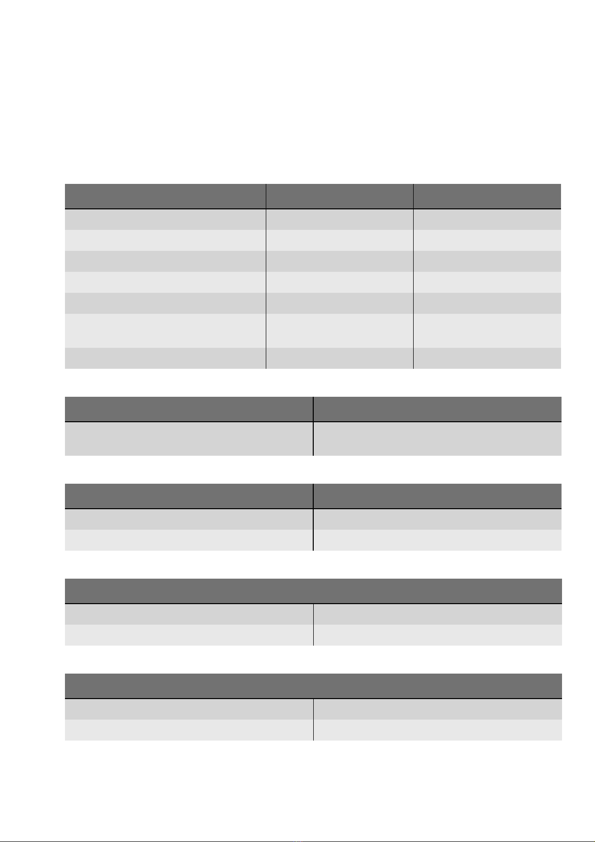
Component affected Description of the modification
Bipolar resection adapter The bipolar resection adapter can be connected to the multifuc-
tion socket on the VIO. Supplement to the safety check to test the
bipolar resection adapter.
Setup 2 settings New setup setting ° modes
Generator adjustment Generator adjustment is possible without APC 2.
Component affected Description of the modification
Setup 2 settings New setup setting AUTO START Limit

2 •Modifications
12 / 110
80116-288_V23381
2022-04
From VIO version 2.7.x
Hardware
No changes
Software
Component affected Description of the modification
Setup 2 settings New setup setting BiCision SC Info.
13 / 110
3 •Controls
80116-288_V23381
2022-04
CHAPTER 3
Controls
Note: This chapter contains an overview of the controls of the unit(s). The
relevant User Manual for the unit(s), knowledge of which is assumed for
servicing work, provides detailed information about how to use the unit(s).
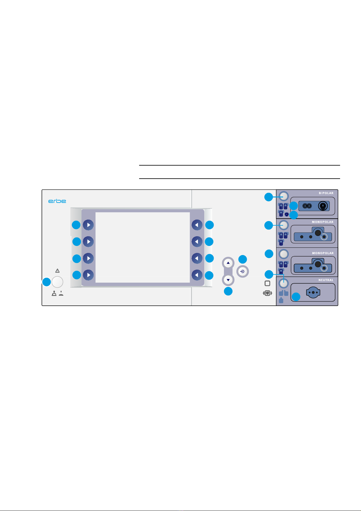
Controls at the front
Fig. 3-1
1Power Switch
2 – 9 Selection buttons
10 Up/Down buttons
11 Enter button
12 – 15 Focus buttons
16 Indicator lights for footswitches
17 Indicator light for AUTO START
18 Indicator lights for neutral electrode
VIO 300 D
F
1
2
3
4
5
6
7
8
9
10
11
12
13
14
15
16
17
18

3 •Controls
14 / 110
80116-288_V23381
2022-04
Controls at the rear
Fig. 3-2
ECB
234
1
1 Footswitch sockets
2ECB socket (Erbe Communication Bus)
3Grounding terminal pin
4Power supply module with fuses
15 / 110
4 •Technical Data
80116-288_V23381
2022-04
CHAPTER 4
Technical Data
Power connection
Rated supply voltage 100 V – 120 V (± 10%) 220 V – 240 V (± 10%)
Rated supply frequency 50 / 60 Hz 50 / 60 Hz
Line current 8 A 4 A
Power input in standby mode 40 watts 40 watts
Power input with max. HF output 500 watts / 920 VA 500 watts / 920 VA
Terminal for grounding (potential equal-
ization)
yes yes
Power fuses T 8 A H / 250 V T 4 A H / 250 V
Operating mode
Intermittent operation ON time 25% (e.g. activated for 10 sec. / deacti-
vated for 30 sec.)
Dimensions and weight
Width x height x depth 410 x 165 x 380 mm / 16.1" x 6.5" x 15.0"
Weight 9.5 kg / 20 lbs. 17 oz.
Ambient conditions for transport and storage of unit
Temperature -40 °C to +70 °C / -40 °F to +158 °F
Relative humidity 10% – 95%
Ambient conditions for operation of unit
Temperature +10 °C to +40 °C / +50 °F to +104 °F
Relative humidity 15% – 80%, noncondensing

4 •Technical Data
16 / 110
80116-288_V23381
2022-04
Acclimatizing
If the unit has been stored or transported at temperatures below +10 °C (+50 °F) or above +40 °C (+104 °F),
the unit will require approx. 3 hours to acclimatize at room temperature.
Standards
Protective class according to UL 2601-1 I
Classification according to EC Directive 93/42/EEC II b
Protection class as per EN 60 601-1 I
Type as per EN 60 601-1 CF

17 / 110
5 •Circuit Descriptions
80116-288_V23381
2022-04
CHAPTER 5
Circuit Descriptions
5 •Circuit Descriptions
18 / 110
80116-288_V23381
2022-04
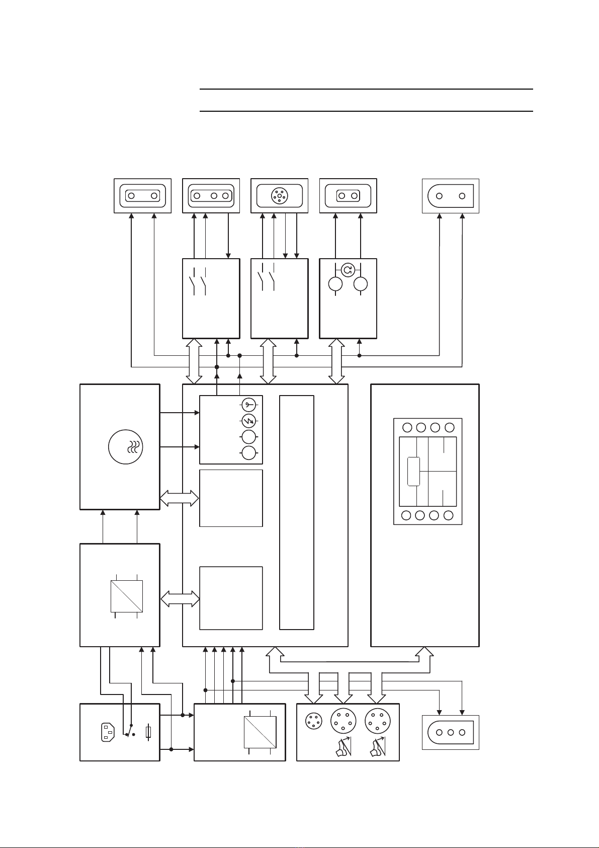
Block diagram VIO 300 D
Fig. 5-1
SCI
SCI
SPI
115 V
230 V
AC
DC
AC
DC
ECB
1
2
AE NE
AE
NE
AE
NE
AE
NE
A
A
IK
LN
CUT COAG
NE1
NE2
ECB ERBE Communication Bus
Power Supply HF generator II
CPU + Sensors II
Line Input
I.v. supply
Power Supply
Control
Generator
Control
CPLD
Sensors
Controller Unit
IIF
NESSY2 II
User Interface
AE
NE
Display
Keyboard
Power PC
Operating
Voltages
AK
AE
NE
AK
Instrument
Interface
VA
IIF
Instrument
Interface
G
0...450V
0...3,5A
230V 50Hz
115V 60Hz
BIPOLAR
MONOPOLAR/
MF/
NEUTRAL
Connector
to APC 2
AK: Aktivierungserkennung
activation recognition
IK: Instrumentenerkennung
instrument recognition
+5V
+15V
+24V
0V
-15V
Connector
to APC 2
BIPOLAR
MONOPOLAR

19 / 110
5 •Circuit Descriptions
80116-288_V23381
2022-04
Description of the various assemblies
Line input
The VIO system can be operated with a line voltage of either 220 – 240 V
or 100 – 120 V. For this the corresponding value (230 V for a line voltage
of 220 – 240 V or 115 V for 100 – 120 V) must be visible in the inspection
window on the power connection, and fuses corresponding to the value
given on the rating plate must be used.
Low voltage power supply unit (l.v. supply)
The low voltage power supply unit produces the operating voltages +5 V,
+15 V, –15 V and +24 V. A special socket on the underside of the unit is
used to supply the +24 V voltage to other system components (e.g. APC 2).
The input voltage range for this power supply unit is 90...264 V with 50 or
60 Hz. Switching over the line voltage at the power connection has no ef-
fect on this power supply unit.
Pin assignment
Fig. 5-2

5 •Circuit Descriptions
20 / 110
80116-288_V23381
2022-04
Power supply (high-voltage power supply unit)
The high-voltage power supply unit provides the HF generator with a DC
voltage which may reach 450 V. It depends on the surgical effect selected
and the alternating voltage necessary for this.
The line input voltage is directly rectified using a bridge-connected recti-
fier. The AC line voltage of 230 V changes to a DC voltage of approx. 320
V; this can be checked between MP3 (ground) and the holding clips of the
fuse holder.
If the power connection is set to 115 V, the bridge circuit becomes a volt-
age doubler connection, also producing approx. 320 V.
The input circuit contains two NTC resistors to limit the high charging cur-
rent which flows when the unit is switched on. Once the capacitors of the
high-voltage power supply unit are charged, limitation is no longer neces-
sary. The NTC resistors are therefore jumpered during activation via the
closed contacts of relay Rel10.
The resulting DC voltage is changed by a chopper regulator and supplied
to a transformer. The transformer is equipped with two identical output
windings which produce a DC voltage through the rectification. With relay
Rel13 these two output windings can be connected either in series or in
parallel, resulting in two operating ranges for the power supply unit: in the
range up to 250 V the maximum output current is 3.5 A, and in the range
up to 450 V 1.75 A max. is possible.
The high voltage power supply unit is controlled by two analog inputs:
The nominal voltage is predefined at J21 pin 11. Thus 4.5 V control voltage
results in a power supply unit output voltage of 450 V. The current limita-
tion is predefined at pin 9. Here 5 V corresponds to the maximum current
of 3.5 A.
Measuring equipment for voltage and current is available. The measured
values are also reported back analogously to pin 8 (voltage actual value)
and pin 6 (current actual value) with the same gain factor.
In addition, there are also two control inputs available: an enable signal
(pin 7 5 V –> off), with which the high voltage power unit can be switched
on and off, and the activation for the discharge circuit (pin 1 5 V –> on),
with which the output capacitors can be discharged.
Other manuals for VIO 300 D
5
Table of contents
Other Erbe Medical Equipment manuals


Erbe
Erbe ICC 200 User manual

Erbe
Erbe BiClamp 110/340 User manual

Erbe
Erbe 20183-067 User manual

Erbe
Erbe APC 2 User manual

Erbe
Erbe LAP BiSect User manual

Erbe
Erbe 20191-331 Operating instructions

Erbe
Erbe 20191-395 User manual

Erbe
Erbe 20191-179 Operating instructions

Erbe
Erbe ERBOTOM ICC 300 User manual

Erbe
Erbe 20150-020 Operating instructions


