FAAC 959 B-E User manual

959 B-E
959 B-E
ist umweltfreundlich
100% Altpapier
pour la nature
papier recyclé 100%
for nature
recycled paper 100%
per la natura
carta riciclata 100% para la naturaleza
100% papel reciclado
C
E
R
M
E
T
A
Z
I
E
N
D
A
C
E
R
T
I
F
I
C
A
T
A
UNI EN ISO 9001-085

ENGLISH
EC MACHINE DIRECTIVE COMPLIANCE DECLARATION
(DIRECTIVE 89/392 EEC,APPENDIX II,PART B)
Manufacturer: FAAC S.p.A.
Address: Via Benini, 1
40069 - Zola Predosa
BOLOGNA - ITALY
Hereby declares that: the 959 B-E automation system
•isintendedtobeincorporatedintomachinery,ortobeassembledwithother
machinery to constitute machinery in compliance with the requirements of
Directive 89/392 EEC, and subsequent amendments 91/368 EEC, 93/44 EEC
and 93/68 EEC;
•complieswiththeessentialsafetyrequirementsinthefollowingEECDirectives:
73/23 EEC and subsequent amendment 93/68 EEC.
89/336 EEC and subsequent amendments 92/31 EEC and 93/68 EEC.
and furthermore declares that unit must not be put into service until the
machinery into which it is incorporated or of which it is a component has
been identified and declared to be in conformity with the provisions of
Directive89/392EECandsubsequentamendmentsenactedbythenational
implementing legislation.
Bologna, 1 January 1997
Managing
Director
A. Bassi

ENGLISH
IMPORTANT NOTICE FOR THE INSTALLER
GENERAL SAFETY REGULATIONS
1) WARNING! FAAC strongly recommends to follow these instructions literally for the safety of persons. Improper
installation or misuse of the product will cause very serious damages to persons.
2) Packaging material (plastic, polystyrene etc.) is a potential hazard and must be kept out of reach of children.
3) Read the instructions carefully before installing the product.
4) Keep these instructions for future reference.
5) Thisproduct hasbeen designed andmanufactured onlyforthe usestated in thismanual. Anyotheruse notexpressly
set forth will affect the reliability of the product and/or could be source of hazard.
6) FAAC S.p.A. cannot be held responsible for any damage caused by improper use or different from the use for which
the automation system is destined to.
7) Do not use this device in areas subject to explosion: the presence of flammable gas or fumes is a serious hazard.
8) Mechanical constructive elements must comply with CEN pr EN 12650-1 and CEN pr EN 12650-2 standards.
CountriesoutsidetheECshallfollowtheregulationsabovebesidestheirnationalnormativereferencesinordertooffer
the utmost safety.
9) FAAC cannot be held responsible for failure to observe technical standards in the construction of gates and doors,
or for any deformation of the gates which may occur during use.
10) Before carrying out any operations, turn off the system’s main switch.
11) An omnipower switch shallbeprovidedforthe installation with anopeningdistanceofthe contacts of 3mmormore.
Alternatively, use a 6A thermomagnetic breaker with multi-pole switching.
12) Ensure that there is a differential switch up-line of the electrical system, with a trip threshold of 0.03A.
13) Check thattheearthing plantisin perfectconditionand connectitto themetallicparts. Alsoearththe yellow/green
wire of the operator.
14) The automation is fitted with an anti-crush safety system that is a torque control device. In any case, further safety
devices shall be installed.
15) Thesafetydevices(e.g.photocells,safety edges,etc.)protectareaswherethereisamechanicalmovementhazard,
e.g. crushing, entrapment and cutting.
16) Each installation must be fitted with at least one warning plate suitably fixed to the gate, besides the safety devices
as per point 15. above.
17) FAAC cannotbeheld responsibleregardingsafety andcorrect functioning ofthe automation inthe event thatparts
other than FAAC original parts are used.
18) Use only FAAC original spare parts for maintenance operations.
19) Do not carry out any modifications to automation components.
20) The installer must supply all information regarding manual operation of the system in the event of an emergency and
provide the end-user with the leaflet attached to the product.
21) Keep out of persons when the product is in operation.
22) Keepout of reach ofchildrentheremoteradiocontrolsandanycontroldevices. The automation could beoperated
unintentionally.
23) The end-user mustavoidanyattemptto repair oradjusttheautomationpersonally. These operationsmustbecarried
out exclusively by qualified personnel.
24) What is not explicitly stated in these instructions is not permitted.

3
ITALIANO
Fig. 2a
Fig. 3
Fig. 2b
Fig. 4 Fig. 8
2x0,5 mm
2
2x0,5 mm
2
2x0,5 mm
2
3x1,5 mm
2
230 V˜
2 x 0,5 mm
2
6 5 437
182 2
2x0,5 mm
2
(schermato
•
screened
•
blindé
•
abgeschimt
•
apantallado)

4
ITALIANO
Fig. 5
90˚ 90˚
2
12
1
3
7
6
5
4
2
1
(a) (b)
45˚
45˚
1
3
2
1
4
4
1
(a) (b)
Fig. 6

5
ITALIANO
Piano di foratura •Drilling template •Schéma de perçage •Bohrbild •Plano de perforación
Quote d'installazione • Installation distances • Cotes d’implantation • Installationsmaße • Cotas de instalación
530
(*) 64 100
530
100
(*)64
0 - 125 (Var. 01)
126 - 250 (Var. 02)
˜ 385
(*) Quota con prolunga albero standard.
Nel caso sia necessario aumentare la di-
stanzatra l'operatore edil braccio sostituire
la prolunga standard con una delle due
prolungheopzionali:
- prolunga albero 20 mm
- prolunga albero 50 mm
In tal caso aumentare le quote interessate
dell'altezza relativa (+20 o +50 mm)
(*) MaßmitStandard-Wellenverlängerung.
BeigrößeremAbstandzwischenAntriebund
Arm die Standardverlängerung durch eine
der beiden optionalen Verlängerungen
ersetzen:
- Wellenverlängerung 20 mm
- Wellenverlängerung 50 mm
In diesem Fall ebenfalls die betreffenden
Höhenmaßevergrößern(+20bzw.+50mm).
(*) Cota con prolongación del eje estándar.
Si fuera necesario aumentar la distancia
entre el actuador y el brazo, sustituir la
prolongación del eje estándar por una de
lasopcionales:
- prolongación de 20 mm
- prolongación de 50 mm
Ental caso, sumaralas cotas interesadasla
altura correspondiente (20 ó 50 mm).
Quote in mm • Dimensions in mm • Cotes en mm • Maßangaben in mm • Cotas en mm
(*) Distance with standard extension.
If a greater distance between the operator
andthearmisrequired,replacethestandard
extensionwithoneoftheoptionalextensions:
- 20 mm extension
- 50 mm extension
In this case increase the corresponding
height values (+20 or +50 mm)
(*) Cote avec rallonge d’arbre standard.
Dans le cas d’installation nécessitant une plus
grande distance entre l’opérateur et le bras,
remplacerlarallongestandardparunedesdeux
rallonges en option:
- rallonge d’arbre de 20 mm
- rallonge d’arbre de 50 mm
Le cas échéant, augmenter les cotes selon le
modèlederallonge choisi (+20mmou + 50 mm).
Tav. A: MONTAGGIO SULL’ARCHITRAVE (BRACCIO ARTICOLATO A SPINGERE) • Table A: LINTEL MOUNTING (PUSHING ARTICULATED ARM)
Schéma A: MONTAGE SUR LE LINTEAU (BRAS ARTICULÉ À POUSSER)
• Übersicht A: STURZEINBAU (DRÜCK-GELENKARM)
Lám. A: MONTAJE EN EL DINTEL (BRAZO ARTICULADO DE EMPUJE)
53 172 292
M6
72
(*)58
M6
14
0 - 14
402 45
(*)
45 402
M6
M6
53
172
292
14
0 - 14
72
(*)58
285 140
56
104
56
104
140 285

6
ITALIANO
Tav. B: MONTAGGIO SULLA PORTA (BRACCIO ARTICOLATO A SPINGERE) • Table B: DOOR MOUNTING (PUSHING ARTICULATED ARM)
Schéma
B:
MONTAGE SUR LA PORTE (BRAS ARTICULÉ À POUSSER)
• Übersicht B: TÜREINBAU (DRÜCK-GELENKARM)
Lám. B: MONTAJE EN LA PUERTA (BRAZO ARTICULADO DE EMPUJE)
Piano di foratura •Drilling template •Schéma de perçage •Bohrbild •Plano de perforación
Quote d'installazione • Installation distances • Cotes d’implantation • Installationsmaße • Cotas de instalación
530
64 (*)100
530
64 (*)
100
˜ 385
Quote in mm • Dimensions in mm • Cotes en mm • Maßangaben in mm • Cotas en mm
(*) Quota con prolunga albero standard.
Nel caso sia necessario aumentare la di-
stanzatra l'operatore edil braccio sostituire
la prolunga standard con una delle due
prolungheopzionali:
- prolunga albero 20 mm
- prolunga albero 50 mm
In tal caso aumentare le quote interessate
dell'altezza relativa (+20 o +50 mm)
(*) MaßmitStandard-Wellenverlängerung.
BeigrößeremAbstandzwischenAntriebund
Arm die Standardverlängerung durch eine
der beiden optionalen Verlängerungen
ersetzen:
- Wellenverlängerung 20 mm
- Wellenverlängerung 50 mm
In diesem Fall ebenfalls die betreffenden
Höhenmaßevergrößern(+20bzw.+50mm).
(*) Cota con prolongación del eje estándar.
Si fuera necesario aumentar la distancia
entre el actuador y el brazo, sustituir la
prolongación del eje estándar por una de
lasopcionales:
- prolongación de 20 mm
- prolongación de 50 mm
Ental caso, sumaralas cotas interesadasla
altura correspondiente (20 ó 50 mm).
(*) Distance with standard extension.
If a greater distance between the operator
andthearmisrequired,replacethestandard
extensionwithoneoftheoptionalextensions:
- 20 mm extension
- 50 mm extension
In this case increase the corresponding
height values (+20 or +50 mm)
(*) Cote avec rallonge d’arbre standard.
Dans le cas d’installation nécessitant une plus
grande distance entre l’opérateur et le bras,
remplacerlarallongestandardparunedesdeux
rallonges en option:
- rallonge d’arbre de 20 mm
- rallonge d’arbre de 50 mm
Le cas échéant, augmenter les cotes selon le
modèle de rallonge choisi (+ 20 mm ou + 50 mm).
45408
M6
14 0 - 14
292172
128
72 58 (*)
128172292
72 58 (*)
M6
14 0 - 14
40845
M6
285140
56
104
140285
56
104

7
ITALIANO
Tav. C: MONTAGGIO SULL’ARCHITRAVE (BRACCIO A PATTINO)•
Table C: LINTEL MOUNTING (SLIDING ARM)
•
Schéma C: MONTAGE SUR LE LINTEAU (BRAS À PATIN) •
Übersicht C: STURZEINBAU (GLEITARM)
Lám. C: MONTAJE EN EL DINTEL (BRAZO CON PAT
Í
N )
Piano di foratura •Drilling template •Schéma de perçage •Bohrbild •Plano de perforación
Quote d'installazione • Installation distances • Cotes d’implantation • Installationsmaße • Cotas de instalación
Quote in mm • Dimensions in mm • Cotes en mm • Maßangaben in mm • Cotas en mm
(*) MaßmitStandard-Wellenverlängerung.
BeigrößeremAbstandzwischenAntriebund
Arm die Standardverlängerung durch eine
der beiden optionalen Verlängerungen
ersetzen:
- Wellenverlängerung 20 mm
- Wellenverlängerung 50 mm
In diesem Fall ebenfalls die betreffenden
Höhenmaßevergrößern(+20bzw.+50mm).
(*) Cota con prolongación del eje estándar.
Si fuera necesario aumentar la distancia
entre el actuador y el brazo, sustituir la
prolongación del eje estándar por una de
lasopcionales:
- prolongación de 20 mm
- prolongación de 50 mm
Ental caso, sumaralas cotas interesadasla
altura correspondiente (20 ó 50 mm).
0 ... 160
(*) Quota con prolunga albero standard.
Nel caso sia necessario aumentare la di-
stanzatra l'operatore edil braccio sostituire
la prolunga standard con una delle due
prolungheopzionali:
- prolunga albero 20 mm
- prolunga albero 50 mm
In tal caso aumentare le quote interessate
dell'altezza relativa (+20 o +50 mm)
(*) Distance with standard extension.
If a greater distance between the operator
andthearmisrequired,replacethestandard
extensionwithoneoftheoptionalextensions:
- 20 mm extension
- 50 mm extension
In this case increase the corresponding
height values (+20 or +50 mm)
(*) Cote avec rallonge d’arbre standard.
Dans le cas d’installation nécessitant une plus
grande distance entre l’opérateur et le bras,
remplacerlarallongestandardparunedesdeux
rallonges en option:
- rallonge d’arbre de 20 mm
- rallonge d’arbre de 50 mm
Le cas échéant, augmenter les cotes selon le
modèlede rallongechoisi (+ 20mm ou +50 mm).
104
104
600
172
292
72
M6
M6
33
170
51
81 (*)
172 292 33
M6
72
51
81 (*)
M6
170600
530
(*) 67 100
160 620
265
530
160620
265
(*) 67 100

8
ENGLISH FAAC 959 B-E
Table 1: Technical specifications of 959 B-E Operator
Power supply 230 Vac (+6 -10%) - 50 (60) Hz
Absorbed power 100 W
Current drawn 0.5 A
Electric motor 24 Vdc with encoder
Dimensions 530 x 100 x 104 (length x height x depth)
Weight 10 kg
Ambient temperature -15 + 70 °C
Housing protection IP 23
Dimensions and max. weight of leaf see Table 3 (section 1.1)
Duty cycle continuous
Operation in event of power failure Manualpush/pullopening
Configuration of driving arms •pushingarticulatedarm
(version for jamb depth 0 ÷125 mm)
•pushingarticulatedarm
(version for jamb depth 126 ÷250 mm)
• sliding arm
Anti-crushing device standard
Opening angle 70 ÷95°
Opening time 3.5 ÷10 s (adjustable)
Closing time 6 ÷13 s (adjustable)
Max. weight of leaf
(kg)
Sliding arm
a
Cable hole
b
Support profile
c
959 MP electronic control unit
d
Position monitoring microswitch
e
Transmission shaft
f
Transmission shaft
f
Drive system
g
DC motor
h
959 B-E programming unit
i
Protective casing
j
Operating function switch
k
End cover (2)
Fig. 1
3
1
2
5
6
11
10
9
8
7
4
Max. weight of leaf
(kg)
Pushing articulated arm
Length of leaf
(mm)
mm
Sliding arm
Table 2: Technical specifications of 959MP Electronic Control
Unit + 959 B-E Programming unit
Power supply 230 Vac (+6 -10%) - 50 (60) Hz
Accessories power supply 24 Vdc / 500 mA max.
Electric lock power supply (N.O./N.C.) 24 Vdc / 0.5 A max.
Standard operating functions (switch) Open / Automatic / Manual
(Night)
Adjustable functions (trimmer) Openingspeed-Closingspeed
Pulling force - Pause time
Selectable functions (microswitches) Overclosingstroke
Standard/non-standardinitialisationprocedure
Push and Go - Function switch (pos. “0”)
Terminal strip outputs Malfunctionalarmsignal-
24 Vdc electric lock power supply
(N.O./N.C.)- 24 Vdc accessoriespowersupply
Terminal strip inputs Functionswitch/CODIS(optional)-
Internal / external / emergency /
STOP safety device / CLOSURE safety device
1.1 APPLICATION LIMITS
Important: To ensure correct application of the FAAC 959 B-E
unittheweightof the door must not exceed the value given in
Table 3 corresponding to its length.
The maximum length of the leaf is 1000 mm.
The values of maximum weight vary according to the driving
arm used.
Foreachdrivingarmthereisalsoadifferentmaximumvaluefor
the depth of the doorpost (Table 4) beyond which it is not
possible to install the system correctly.
Table 3: Application limits of 959 B-E automatic unit
700 130 -
750 124 -
800 118 92
850 113 89
900 108 85
950 104 83
1000 100 80
Table 4: Max. depth of doorpost
2. ELECTRICAL SETUP (fig. 2a Standard system)
a
959 B-E operator
b
Microwave radar / Passive infrared sensor
c
T20E external key-switch (KEY command)
d
Emergency Closing/Opening pushbutton
e
CODIS programming unit (optional)
f
CODIS inhibition switch (optional)
g
24 Vdc electric lock
h
Junction box
If the operator is installed on the door, make the electrical
connections using a junction box and suitable commercially
available pipes/unions (fig. 2b).
Pushing
articulated arm
(Var. 02)
Pushing
articulated arm
(Var. 01)
0 - 125 126 - 250 0 - 160
The 959 B-E automatic unit for swing doors is a one-piece unit
consisting of an electromechanical device that allows door
opening to be controlled by means of a driving arm.
Theoperatorcan beinstalledeitheron thelinteloron thedoor
structure itself.
Thealuminiumprotectivecasinghousestheelectroniccontrol
unit used to program and control the operation of the system.
In the event of a power failure the door can be pushed (or
pulled) open manually.
1. DESCRIPTION AND TECHNICAL CHARACTERISTICS

9
ENGLISH
N.B.: 1) For installation of electrical cables use suitable rigid
or flexible piping.
2) Alwayskeepthelowvoltageaccessoryconnection
cables separate from the 230 V power cables. Use
separate sheaths to avoid any interference.
3. INSTALLATION
3.1 PRELIMINARY CHECKS
Toensurecorrectoperationoftheautomaticunitthestructure
of the existing door must meet the following requirements:
-
length and weight as specified in Table 3 (section 1.1);
- max. doorpost depth as specified in Table 4;
- robust and rigid structure of the leaf;
- good condition of the existing hinges;
- smooth, uniform movement of the leaf with no abnormal
friction at any point of its travel;
-
“neutral” position of the door during its entire travel. If the
door tends to close or open, check the alignment of the
hinges.
- Presence of mechanical end stops.
3.2 MOUNTING THE OPERATOR
1) Remove the protective casing (fig. 3) and the end covers
(fig. 4) from the operator.
Warning: Before removing the end cover with the function
switch, remove the connector joining the switch to the 959MP
electronic control unit.
2)
As regards the mounting position of the operator (on the
lintel or on the door) and the type of arm to use (pushing,
pullingorsliding), refertotherelevantmountingtableand
drill the holes required to mount the operator and the
pulling arm.
N.B.: The two intermediate operator fixing holes are not in a
central position (see mounting tables). The holes are offset in
order to ensure that the operator is mounted with the correct
direction of rotation of the mechanism.
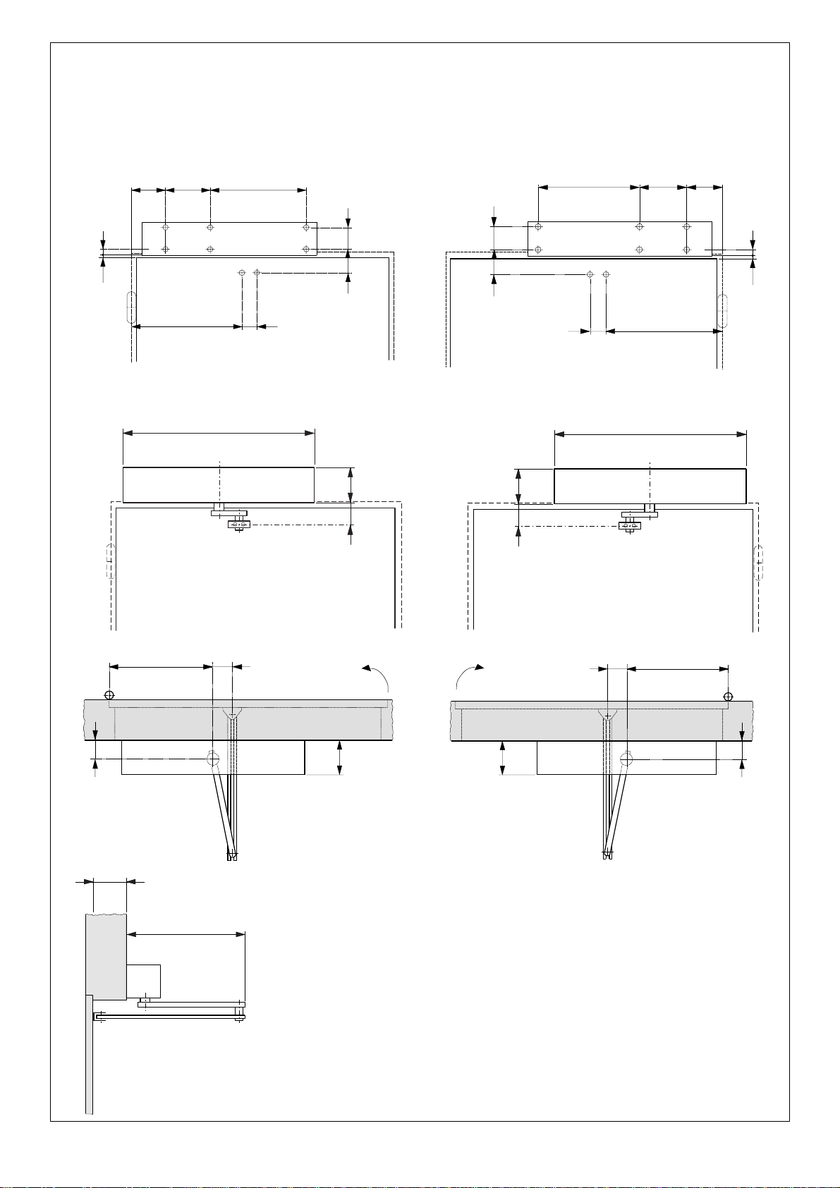
The mounting tables are the following:
Table A: LINTEL MOUNTING (PUSHING ARTICULATED ARM)
Outward opening
Table B: DOOR MOUNTING (PUSHING ARTICULATED ARM)
Inward opening
Table C: LINTEL MOUNTING (SLIDING ARM) Inward opening
3) Mount the operator using the six M6 screws and washers
provided.
Warning:
- The structure of the lintel (or the door) at the operator
mounting position must not exhibit any significant
deformation.
- The operator must be mounted parallel to the floor.
N.B.: If the sliding arm is to be used, the driving arm must be
mounted before the operator is fixed on the lintel (see section
3.3.3.).
3.3 MOUNTING THE DRIVING ARMS
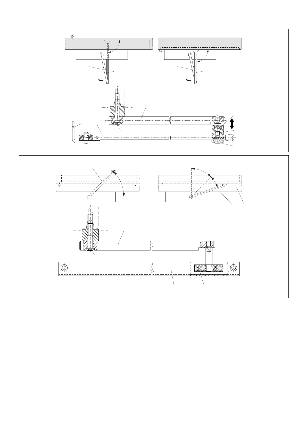
3.3.1 MOUNTING THE PUSHING ARTICULATED ARM (fig. 5)
1) Close the door.
2) Free arms (1) and (2) by pulling apart the coupling (3)
manually as shown in fig. 5.
3) Fit arm (1) on the operator transmission shaft by means of
the extension and the screw (4) provided (fig. 5). The arm
must be mounted perpendicular to the closed door.
N.B.:
If a greater distance between the operator and the arm
is required, use the higher extensions available as accessories
(see Table A/B).
4) Mountplate(5)ofarm(2)onthedoororthelintelusingthe
two M6 screws and the washers provided (fig. 5). The
installation distances are given in Table A/B.
5) Slackenthefixingscrew (6) andassemblethetwoarms by
means of coupling (3) (fig. 5).
6) Turn arm (1) until arm (2) is perpendicular to the closed
door or the lintel as shown in fig. 5 (a-b), sliding the spacer
(7) along arm (2).
7) Tighten the fixing screw (6) between the two arms.
The length of arm (2) is given in the relevant mounting
tables.Ifnecessary,cutoffthesectionofthearmextending
beyondthearticulationandthencovertheendsusingthe
caps provided (fig. 5).
8) Check manually that the door is free to open and close
fully and that it comes to rest against the mechanical end
stops.Ifthedoordoesnotclosecorrectly,adjustthereturn
spring as described in section 10.
3.3.2 MOUNTING THE SLIDING ARM (fig. 6)
1) Mountarm(1)ontheoperatortransmissionshaftbymeans
of the extension and the screw (2) provided (fig. 6). The
arm must be fitted pointing 45° outwards as shown in fig.
6(a).
N.B.: Ifa larger distance is required between theoperatorand
thearmusethehigherextensionsavailableasaccessories(see
Table C).
Warning: Mount arm (1) on the transmission shaft before fitting
the operator on the lintel (fig. 6).
2) Insert the roller (3) inside the sliding guide (4) (fig. 6).
3) Pull arm (1) inwards manually as shown in fig. 6(b) and
secure the sliding guide (4) by means of two M6 screws on
the closed door as shown in Table C.
4) Check manually that the door is free to open and close
fully and comes to rest against the mechanical end stops.
Ifthedoordoesnotclosecorrectly,adjustthereturnspring
as described in section 10.
4. START-UP
1) Make the electrical connections to the 959 MP electronic
control unit as described in section 6.
Togainaccessto thecontrolunit,passthe cables through
the special conduit (fig. 1 - ref. 1) as shown in fig. 8.
2) Fitthetwoendcoversandconnectupthefunctionswitch.
Theendcoverwiththeswitch may be fitted on the right or
the left. For cable routing refer to fig. 8.
3) Turn the operating function switch (fig. 1 - ref. 12) to
position I (AUTOMATIC logic).
4) Check that the programming unit microswitches (fig. 10)
are all in the OFF position.
Important:Whenmountingthe“pullingarticulated”or“sliding”
arms or for opening angles greater than 90°, turn microswitch
no. 2 to ON before connecting power to the system.
5) Close the door.
6) Poweruptheoperator.Poweringissignalledbyanacoustic
signal from a buzzer.
7) Check that the 5V LED on the programming unit (fig. 9)
lights up.
8) Attheendof the initialisation procedure, check the status
ofthesignallingLEDs on the programming unit as shown in
Table 5.

1 0
ENGLISH
Table 5: Operation of status LEDs
²
LED ON OFF
5 V logic powered logic not powered
OK command active command inactive
YES safety devices active safety devices inactive
N.B.: ThestatusoftheLEDswiththe door closed at rest isshown
in bold type.
4.1. INITIALISATION PROCEDURE
As soon as the system is powered up, it runs an initialisation
procedure which includes setting the following parameters:
- measuring the mass of the door;
- determining the end stop positions;
- determining the point at which the STOP safety device
intervenes (see section 6).
The door opens at low speed, then closes half way before
switching back to opening.
Subsequent closure is performed by the return spring.
The initialisation procedure is indicated by an intermittent
acoustic signal (frequency 1 sec) emitted by a buzzer on the
programming unit (table 6).
The process may be inhibited due to:
- function switch in the 0 (MANUAL) position;
- incorrect connection of the accessories (electric lock,
control/safety devices);
- incorrectpositioningoftheprogrammingunitmicroswitches.
N.B.: TorepeattheinitialisationprocedureholddowntheRESET
button (fig. 11 - ref. 4) for more than 4 seconds.
5. 959 B-E PROGRAMMING UNIT
5.1 LAYOUT AND DESCRIPTION
5.2. SETTING THE ADJUSTING TRIMMERS
The programming unit features trimmers (fig. 9 - ref. 3) which
regulate the following parameters:
Trimmer Vo to set the opening speed.
Setting 30 ⇒100% of the initialisation value.
Standard setting 50%.
Trimmer Vc to set the closing speed.
Setting 30 ⇒100% of the initialisation value.
Standard setting 50%.
N.B.: The speed initialisation values depend on the dimensions
and the mass of the door.
Trimmer To to set the pause time (AUTOMATIC logic).
Setting from 1 to 30 seconds.
Standard setting 3 seconds.
Trimmer Fm to set the pulling force of the operator.
Setting 60 ⇒100% of maximum value.
Standard setting 100%.
Turn the trimmers clockwise to increase the values of the
settings.
Turn the trimmers anticlockwise to reduce the values of the
settings.
5.3. PROGRAMMING THE MICROSWITCHES (fig. 10)
The programming unit has a series of microswitches which
allow the functions shown in fig. 10 to be selected.
The system is supplied with all the microswitches in the OFF
position.
5.3.1. OVERCLOSING STROKE
Thisfunctionenablestheclosedpositionforcetobeincreased
by further loading the transmission system after the door has
reached the mechanical closure end stop.
It is advisable to use this function if the door is subject to
pressure caused by atmospheric agents (e.g. gusts of wind)
when closed.
5.3.2. INITIALISATION PROCEDURE
If pulling articulated arms or sliding arms are mounted or in the
eventofopeninganglesofmorethan90°,theNON-STANDARD
processmustbeselected.In this case anexternalmechanical
stop must always be provided.
5.3.3. FUNCTION SWITCH (“0” POSITION)
This function allows the operating function to be selected with
the switch in the “0” position (see section 7).
5.3.4. PUSH AND GO
Whenactivated,thisfunctionenablestheopeningcommand
tobegiven bypushingtheclosed doormanually.Itis sufficient
to give the door an initial push in the opening direction.
5.4. SIGNALLING BUZZER
The programming unit incorporates a buzzer which emits
sequences of acoustic signals corresponding to different
statuses of the system. The statuses that have occurred and
their identification sequence can be seen in Table 6.
S1 S2 S3 S4 S5 S6
S2
Initialisation
procedure
OFF Standard
ON Non-standard
S1
Overclosing stroke
OFF Inactive
ON Active
S3
Function switch
position “0”
OFF Manual
ON Night
S4
“Push and Go”
OFF Active
ON Inactive
S5-S6
Inactive
Fig. 10
ON
N.B.: Press RESET after every programming operation.
▼▼
▼▼
▼
e
Connector (16 pole) for connection
with 959 MP electronic control unit
f
Encoder
g
Connector (2 pole) for connection
with 959 MP electronic control unit
a
Signalling LEDs (see Table 5)
b
Signalling buzzer (see section 5.4.)
c
Adjusting trimmer
d
Programming microswitches
Fig. 9
123456
S1
S2
S3
S4
S5
S6
Fm
To
Vc
Vo
SI
OK
5V
43 2 1
7
65

11
ENGLISH
Suono
Pausa
1 s
4 s
8 s
Sound
Pause
Table 6: Acoustic signals
STATUS SIGNALLED ACOUSTIC SEQUENCE
Connection to mains
power supply
Initialisation procedure
Alarm: Error "A"
Alarm: Error "B"
The indication of error A does not inhibit the operation of the
automationunit.The indication oferrorB inhibits theoperation
of the automation unit until the fault is eliminated.
Table 8 (paragraph 8.4) contains a list of the malfunction
conditionsindicatedbythesystem.Toidentifythefault,connect
the CODIS external programming unit (optional).
6. 959 MP ELECTRONIC CONTROL UNIT
Warning: Always disconnect the electric power supply before
carrying out any work on the control unit (connection,
maintenance).
6. Electric lock - N.O. contact (max. capacity 0.5 A/24 V) (fig.
16). If no power is supplied the electric lock is active and
therefore guarantees-CLOSING mechanical locking. In
the NIGHT function the electric lock is active even if no
power is supplied. In the event of an opening command
(internalcommandorEMERGENCYOPENING),theelectric
lock is temporarily powered to enable the door to be
opened. In this case a reverse stroke command is also
given to enable the mechanical release of the system.
7. Accessories power supply (+24 Vdc)
8. Accessories power supply (0 Vdc)
9. Internal command: any control device (pushbutton,
photocell, sensor, etc.) which, by closing a contact, can
command an opening cycle of the system from inside.
10. External command: any control device (pushbutton,
photocell, sensor, etc.) which, by closing a contact, can
command an opening cycle of the system from outside.
Fig. 17 shows the control device connection. To install
more than one internal/external control device, connect
the N.O. contacts in parallel.
Connecting microwave radar / passive infrared sensors.
In the conventional configurations the control units are
microwave radar and/or passive infrared sensors. To
connect the FAAC sensors/radar units equipped with a 5-
pole electrical cable, refer to fig. 18.
11. Emergency control (fig. 19/a): anycontroldevice(normally
a pushbutton) which, by opening a contact, commands
an emergency closure of the system. Alternatively this
input can be used to command emergency opening by
programming the system in a suitable manner using the
CODIS programming unit (optional).
To install more than one emergency control device,
connect the N.C. contacts in series.
N.B.: If emergency control devices are not connected,
jumper inputs 11 and 15.
Activating function no. 6 at CODIS programming level III
enablestheemergencycontroltobeactivatedbyclosing
a N.O. contact.
In this case, in order to install more than one emergency
control device, connect the N.O. contacts in parallel.
12. STOP safety control (fig. 19/a): any device (safety sensor,
photocell,etc.)which,byopeningacontact,hasasafety
effect on the operating cycle. In particular, this safety
device interrupts the opening/closing movement of the
door.
When the safety device is disengaged, the door resumes
its opening/closing movement and continues to the end
of the cycle.
To install more than one STOP safety device, connect the
N.C. contacts in series.
N.B.: If STOP safety devices are not installed, jumper inputs
12 and 15.
13. CLOSURE safety command (fig. 19/a): any device (safety
sensor, photocell, etc.) which, by opening a contact, has
a safety function on the closing movement of the door.
The safety device causes an immediate reversal of the
closing movement of the door, but has no effect on the
opening movement of the door.
To install more than one CLOSURE safety device, connect
the N.C. contacts in series.
N.B.:IfCLOSUREsafetydevicesarenotconnected,jumper
inputs 13 and 15.
Connection of MINISWITCH photocells
TheMINISWITCHphotocellscanbeusedasasafetydevice.
For connection, see figure 19/b.
14. Accessories power supply (+24 Vdc)
15. - 16. Accessories power supply (0 Vdc)
dRESET button
N.B.: ToRESET,hold down thebuttonforat least 4seconds.
ePosition monitoring microswitch connector (fig. 1 - ref. 4).
fProgramming unit connector (2 pole)
Fig. 11
12345678 9 10 11 12 13 14 15 16 17 18 19 20 21 22 23 24 25 26 27 28
X6
X5
X7
X2 X4
X1
F1
7
6
5
4
3
1
2
aFuse F1 1AT/230Vac - 5x20
bTerminal strip X1 (230 V) - fig. 12
cLow voltage terminal strip X2 / X4
Description of the terminal strip
1. - 2. - 3. Connectionoffunctionswitch(fig.1-ref.12)asshown
in fig. 13.
Connection of CODIS programming unit (optional) as
shown in fig. 14.
Use a 2 x 0.5 mm2screened cable (bus communication)
fortheconnection.Thescreeningmustbefixedunderneath
the special screws (fig. 14 - ref. 1).
Important: The maximum permissible length of the
connection cable is 50 m.
To inhibit operation of the CODIS, interrupt the jumper
betweenterminals3and4andinstallaswitch(fig.14-ref.2).
Warning: If the CODIS is used on a continuous basis,
functionno.7mustbeactivated at level III (see section 8).
Activation of input 3 (fig. 14) enables the NIGHT or ONE-
WAY operating functions to be given priority over the
function selected on the CODIS unit. To select the priority
function, program the CODIS suitably at level III (function
no. 2 - see section 8.3). The input can be activated by
means of a timer.
4. Electric lock - Common
5. Electric lock - N.C. contact (max. capacity 0.5 A/24 V) (fig.
15). The output is suitable for commanding a magnetic
closure system. If no power is supplied, the electric lock is
notactive.IntheNIGHTfunctiontheelectriclockispowered
and hence active. In the event of an opening command
(internal command or EMERGENCY OPENING), the power
supplytotheelectriclockistemporarilycutofftoallowthe
door to be opened.

12
ENGLISH
Fig. 17
Fig. 16
Fig. 15
Fig. 19/a
Fig. 18 Fig. 19/b
Fig. 14
Fig. 13
Fig. 12
0
12
123
white
brown
green
0 Vcc
INTERNAL
COMMAND
0 Vdc
8910
EXTERNAL
COMMAND
45678
EL. LOCK N.C.
EL LOCK N.O.
+24 Vcc
0 Vdc
< 0,5A
max. 0,5A/24 Vdc
EL. LOCK COM.
45678
+24 Vcc
0 Vdc
max. 0,5A/24 Vdc
< 0,5A
EL. LOCK N.C.
EL LOCK N.O.
EL. LOCK COM.
L = screened cable 2 x 0,5 mm
2
; 50 m max.
2
NIGHT
(ONE-WAY)
CODIS
L
L
123
2
1
4
3
0 Vdc
1
1
230 V (+6 -10%)
50 (60) Hz
N.F. N.O.
C±+
INTERNAL SENSOR
N.F. N.O.
C±+
EXTERNAL CONNECTOR
BROWN
WHITE
GREEN
YELLOW
GREY
(not connected)
+24 Vdc
0 Vdc
INTERNAL COMMAND
EXTERNAL COMMAND
GREY
(not connected)
78910
BROWN
WHITE
GREEN
YELLOW
78 13
+ 24 Vdc
0 Vdc
CL. SAFETY
BROWN
WHITE
GREEN
TX RX
MINISWITCH
BROWN
WHITE
N.C.
contacts
11 12 13 14 15
EMERGENCY CLOSURE
(OPENING)
STOP SAFETY
CLOSURE SAFETY
+24 Vdc
0 Vdc

13
ENGLISH
o LED 5 OPEN
The door opens and remains open.
o LED 4 AUTOMATIC
The door opens when internal or
externalcommandsareactive and
re-closes after the pause time.
o LED 3 AUTOMATIC (SPARE)
o LED 2 ONE-WAY
Entry (or exit) inhibited; only one
direction of exit (or entry); opening
wheninternal(orexternal)command
is active; closing after pause time.
The external (or internal) control
devices are inactive.
o LED 1 NIGHT
Thedoorislockedshutbytheelectric
lock.
The external command is inactive.
The door can be opened solely by
activatingtheinternalcommandor
EMERGENCY OPENING input. The
door closes after the night pause
time.
Vc
P
Tp
Vo
1
0
2
Fig. 20
POSITION “1”: AUTOMATIC
When an internal/external command is given, the
door opens and then re-closes after the pause
time.
POSITION “0”: MANUAL/NIGHT
The position “0” can be used to select two different
operatingfunctionsaccordingtotheprogramming
carried out on the 959 B-E programming unit (see
section 5.3).
The two functions are:
MANUAL: The door can be opened manually. The
return spring pulls the door closed again.
NIGHT: The external command is inactive. The door
can be opened solely by activating the internal
command (fig. 17) or EMERGENCY OPENING (fig.
19/a) input.
POSITION “2”: OPEN
When this function is selected, the door opens and
remains open. The door can be closed only by
activating the EMERGENCY CLOSURE input (fig.19/
a).
LEDS DI SEGNALAZIONE
FUNZIONI
REGOLABILI
PULSANTI DI COMANDO
FUNZIONI
OPERATIVE
ERROR
Tpn
Tp
P
Vc
Vo
RESET
6
5
4
3
2
1
OPERATING
FUNCTIONS
STATUS LEDS
PUSHBUTTON
CONTROLS
ADJUSTABLE
FUNCTIONS
8.2. LEVEL II - ADJUSTABLE FUNCTIONS
Important: LevelIIisactiveonlyiftheCODISisusedpermanently
(function7ofLevelIIIactivated).TheCODISprogrammingunit
has one adjusting level.
Six parameters can be set. They are displayed on the right-
hand side of the CODIS front panel, with the relevant LEDs:
RESET LED 6 o RESET: repeat initialisation process
(see paragraph 4.1).
LED 5 o OPENING SPEED:adjustto30⇒100%
of initialisation value.
The standard setting is 100%.
LED 4 o CLOSING SPEED: adjust to 30 ⇒
66% of initialisation value.
The standard setting is 66%.
LED 3 o OPENING EXCURSION: adjust
maximum opening by 60 to 100%.
The standard setting is 100%.
LED 2 o PAUSE TIME:adjustto0-30seconds.
Theopeningiscontrolledbymeans
Fig. 21
gProgramming unit connector (14 pole)
7. FUNCTION SWITCH
The 959 B-E operator has a 3-position function switch (0-1-2)
mounted on one of the end covers (fig. 1 - ref. 12). This cover
can be fitted on the right or the left as required (fig. 8).
The switch electrical connection is shown in fig. 13.
The selectable operating functions are shown in fig. 20.
8. “CODIS” EXTERNAL PROGRAMMING UNIT (OPTIONAL)
The 959 B-E automation unit can also be controlled by an
external programming unit in place of the function selector
and of the 959 B-E programming unit.
The CODIS (see figure 21) has four levels of operation, where
theusercanselecttheoperatingfunctionsandset,programme
and monitor the operation of the system.
If the CODIS is used permanently, it is necessary to activate
function7atLevelIII(programmingfunctions):seeparagraph
8.3.
For the electrical connection of the CODIS, consult figure 14.
The operation of the CODIS can be inhibited in the two
following ways:
- by cutting the jumper between terminals 3 and 4 by means
of a switch (fig. 14);
- byactivatingfunction9atLevelIII;inthiscaseitispossibleto
operate the unit temporarily after having entered code
“+ + - - + +” by means of the “+” and “-” pushbuttons.
After 2 minutes the CODIS will stop again automatically.
Note:theCODIScanalsobeusedasatemporaryprogramming
unit. In this case, Level II (adjustable functions) is inactive.
When the programming of the system has been completed,
theCODIScanberemoved:all theprogrammedfunctionswill
remain unaltered.
Afterhavingremoved theCODIS,performaRESETorswitch off
the system.
8.1 LEVEL I - OPERATING FUNCTIONS
This is the level that is accessible to the user. By pressing either
the“+”orthe“-”pushbutton,theusercanselecttheoperating
function.
Five operating functions are available. They are displayed on
the left-hand side of the front panel of the CODIS.
When a function has been selected, the corresponding LED
lights up on the front panel.
Press the “+” pushbutton to move the lighting of the LEDs one
position up.
Press the “-” pushbutton to move the lighting of the LEDs one
position down.
The five available functions displayed on the panel are:
o LED 6 MANUAL
The door is released and can be
operated manually.
The control devices are inactive.

14
ENGLISH
of the activation of the internal/
external control devices.
The standard setting is 2 seconds.
LED 1 o NIGHT PAUSE TIME: adjust to 0-30
seconds.Theopeningiscontrolled
by means of the activation of the
KEY/EMERGENCY OPENING
commands.
The standard setting is 7 seconds.
8.2.1. ADJUSTMENT OF PARAMETERS
To access Level II (adjustable functions), proceed as follows:
1) Selecttheparametertobeadjustedbycausingtherelevant
LED to light up. Press the “+” pushbutton to move the
lightingoftheLEDsonepositionup.Pressthe“-”pushbutton
to move the lighting of the LEDs one position down.
2) Press the “+” and “-” pushbuttons simultaneously.
The LED relevant to the selected parameter will start
flashing in order to give information about the stored
value: if the flashing rate is high, a high door speed or a
shortpausetime hasbeenstored;iftheflashingrate islow,
a low door speed or a long pause time has been stored.
3) Press the “+” or “-” pushbutton repeatedly, in order to
increase or decrease the flashing frequency of the LED,
that is to say, to change the value of the selected
parameter. When the “+” pushbutton is pressed, the door
speed, opening excursion and pause time are increased.
When the “-” pushbutton is pressed, the door speed,
opening excursion and pause time are decreased.
4) Return to Level I (operating functions) by pressing the “+”
and “-” pushbuttons simultaneously.
Notes: - The CODIS automatically returns to Level I after 2
minutes of inactivity.
- To prevent the settings from returning to standard
values after a RESET or a voltage drop, “protect” the
programmed values by activating function 18 at
Level III (see paragraph 8.3).
8.3. LEVEL: III - PROGRAMMING FUNCTIONS
The CODIS has a programming level where certain functions
can be selected.
These functions are required for several special applications.
Note: a voltage drop or a RESET command will not cancel the
programming on Level III.
Standardprogrammingcanberestoredbymeansoffunction
15 (see Table 7).
To access Level III, proceed as follows:
1) Select the NIGHT operating function by causing LED 1 to
light up. Press the “+” pushbutton to move the lighting of
theLEDsoneposition up.Pressthe“-”pushbutton to move
the lighting of the LEDs one position down.
2) Pressthe“+”and“-”pushbuttonssimultaneouslyforabout
2 seconds, until the red ERROR LED lights up.
3) Enter the access code by pressing the “+” and “-”
pushbuttons in the following sequence: “+ + + - - + + +”.
Note: after the lighting up of the red ERROR LED, if the code is
not entered within 10 seconds the CODIS will automatically
return to Level I.
4) .Selectthefunctiontobeprogrammedbypressingthe“+”
or “-” pushbutton so as to obtain the combination of lit
LEDs indicated in Table 7.
5) Pressthe“+”and“-”pushbuttonssimultaneouslytoactivate
or deactivate the function, and check the status of LED 6,
according to the indications of Table 7.
Note: the standard programming is the one with LED 6 unlit
(OFF).
6) ToreturntoLevelI(operating functions),repeatedly press
the “-” pushbutton until all the six LEDs are off, then press
the “+” and “-” pushbuttons simultaneously.
Note: the CODIS will automatically return to Level I after 2
minutes of inactivity.
FUNCT.NO.
LEDS FUNCTIONS LED 6
12345
0 OFF OFF OFF OFF OFF Output Level III OFF
1 ON OFF OFF OFF OFF One-way with lock active OFF
One-way with lock inactive ON
2 OFF ON OFF OFF OFF NIGHT function (terminal 3-959MP) OFF
ONE-WAY function (terminal ON
3-959MP)
5 ON OFF ON OFF OFF Emergency closing (terminal OFF
11-959MP)
Emergency opening (terminal ON
11-959MP)
6 OFF ON ON OFF OFF Emergency command - N.C. OFF
contact (terminal 11-959MP)
Emergency command - N.O. ON
contact (terminal 11-959MP)
7 ON ON ON OFF OFF CODIS - temporary connection OFF
CODIS - permanent installation ON
8 OFF OFF OFF ON OFF 15 kg static force OFF
9 kg static force ON
9 ON OFF OFF ON OFF CODIS inhibited inactive OFF
CODIS inhibited active ON
10 OFF ON OFF ON OFF Standard opening pause time OFF
Immediate closing ON
15 ON ON ON ON OFF Restore STANDARD settings OFF
Retain programmed settings ON
17 ON OFF OFF OFF ON TEST programme inactive OFF
TEST programme active ON
18 OFF ON OFF OFF ON Level II RESET active OFF
Level II RESET inactive ON
19 ON ON OFF OFF ON STANDARD internal command OFF
(terminal 9-959MP)
STEP-BY-STEP internal command ON
(terminal 9-959MP)
Table 7: programming functions
Tpn
8.3.1. AVAILABLE FUNCTIONS
function 1
One-way with lock activated: in the ONE-WAY operating
function, the closed door is locked by the electric lock.
One-way with lock deactivated: in the ONE-WAY operating
function, the closed door is not locked by the electric lock.
function 2
NIGHT function: the activation of the input between terminals
2 and 3 (959MP) selects the NIGHT operating function, with
priority over the function selected on the CODIS.
ONE-WAY function: the activation of the input between
terminals 2 and 3 (959MP) selects the ONE-WAY operating
function,with priority overthefunctionselectedontheCODIS.
The control panel will show which function has been selected,
by means of the lighting up of LED 1 or 2.
When the input is deactivated, the operating function
previously selected on the CODIS returns automatically.
function 5
Emergency closing: the activation of the input between
terminals11and15(959MP)controls theclosingofthedoorno
matter which operating function has been selected.
Emergency opening: the activation of the input between
terminals 11 and 15 (959MP) controls the opening of the door
no matter which operating function has been selected.

15
ENGLISH
function 6
Emergency command - N.C. contact: to activate the input
between terminals 11 and 15 (see function 5), an opening
pulse of a N.C. contact is required.
Emergency command - N.O. contact: to activate the input
between terminals 11 and 15 (see function 5), a closing pulse
of a N.O. contact is required.
function 7
CODIS - temporary connection: the CODIS can be used only
initially to activate certain functions. When the external
programming unit is removed, the function that has been
activated remains stored. In this case, Level II is inhibited, and
the settings (speed, pause times, etc.) must be performed by
means of the internal 959 B-E programming unit.
CODIS - permanent installation: the CODIS is installed
permanently; the four operating levels are all active.
function 8
15 kg static force / 9 kg static force: this function makes
it possible to change the sensitivity of the anti-crushing
device.
function 9
CODIS inhibited inactive / CODIS inhibited active: this function
makes it possible to activate the CODIS electronic inhibition. In
this condition, no programming can be performed at any level.
To release the CODIS temporarily, press the “+” and “-”
pushbuttons in the following sequence: “+ + - - + +”.
This operation may be carried out for two purposes:
1) to change the operating function or modify some settings
atLevel II; in this case, after2minutestheCODIS inhibition
will come again;
2) to remove the CODIS inhibition; in this case, it is necessary
to access Level III and to disable that function.
function 10
Standard opening pause time: the pause time begins with the
door open and the control devices (e.g., sensors) inactive.
Immediate closing: the door closes when the control devices
(e.g.,sensors)areinactive.Inthiscase,directionalsensorsmust
be used.
function 15
Restore STANDARD settings / Retain programmed functions:
this function makes it possible to check whether any function
has been programmed differently from the standard settings.
If at least one function has been programmed differently from
the standard settings, LED 6 is lit (ON).
In this case all the standard settings can be restored by
pressing the “+” and “-” pushbuttons simultaneously.
After this operation, it is advisable to perform a RESET.
function 17
TESTprogrammeinactive/active:thisfunctionmakesitpossible
toactivateconsecutiveoperatingcycles.Thecontroldevices,
in any case, take priority over the operation of the system. The
programme can be cancelled by performing a RESET.
function 18
LevelIIRESETactive/ inactive:thisfunctionmakesitpossibleto
preserve the settings of the opening, closing and opening
excursion speeds even in case of a voltage drop or RESET.
function 19
STANDARD internal command: the activation of the internal
control device controls a complete door cycle (standard
operation).
STEP-BY-STEP internal command: the activation of the internal
controldevicecontrolsasequenceofdooropening/stopping
/ closing / stopping / opening, and so on.
Table 8
NO. LEDS FAILURE NOTE
1 2 3 4 5 (*)
1 ON OFF OFF OFF OFF
Motor fault
B
2 OFF ON OFF OFF OFF
Governor and brake fault
B
3 ON ON OFF OFF OFF
Initialisation process not possible
B
Opening angle insufficient
4 OFF OFF ON OFF OFF
Initialisation process not possible
B
Opening angle excessive
5 ON OFF ON OFF OFF
Friction or spring load excessive
B
6
7 ON ON ON OFF OFF
Motor overload
B
8 OFF OFF OFF ON OFF
Encoder fault (disconnected
B
or in short circuit)
9 ON OFF OFF ON OFF
Cut-off relay fault
B
10 OFF ON OFF ON OFF
EPROM / RAM / relay fault (automatic
B
control)
11 ON ON OFF ON OFF
Short circuit on 24 V (959MP electronic
B
control unit or external)
12 OFF OFF ON ON OFF
Monitoring microswitch fault
A
13 ON OFF ON ON OFF
Electric lock fault
B
14 ON ON ON ON OFF
Power supply insufficient
(< 140 V) B
15 OFF OFF OFF OFF ON
Microprocessor fault
B
16 ON OFF OFF OFF ON
Incorrect “door closed” position
A
17 OFF ON OFF OFF ON
Microprocessor alarm
B
18
(*)
A
: this error condition does not inhibit the operation of the system.
B
: thiserrorconditioninhibitstheoperationoftheautomationunituntil
the fault has been eliminated.
9. MAINTENANCE
It is advisable to check the automation unit once a year, in
ordertomakesurethatthedraggingsystemandclosingspring
are in perfect working order.
Drive system (fig. 1 - ref. 7)
Check the toothed wheels and, if necessary, lubricate them
with grease for gears or bearings TRIBOTECH VTP 473.
Important: never use spray lubricants.
8.4. LEVEL IV - SELF-DIAGNOSIS
TheCODISprogrammingunithasaself-diagnosticlevel,which,
in case of a fault, interrupts the display of the operating
function every 2 seconds in order to display the malfunction
conditionfor0.5seconds.Thetypeoffaultcanbeidentifiedby
observingthecombinationofLEDs1-5thatarelittogetherwith
the red ERROR LED (see Table 8).

26
ENGLISH
END-USER GUIDE
959 B-E Automation Systems
The different logic modes are active when the corresponding
LED is illuminated steadily. To change the operating function
press the + or - control button.
MANUAL OPERATION
If the door has to be activated manually due to failure of the
electricalpowersupplyoramalfunctionoftheautomaticunit,
proceed as follows:
Function selector
- Turn the selector to the “0” MANUAL/NIGHT position
- Open or close the door manually
CODIS unit
- Pressthe+buttontosettheoperatingfunctiontothemanual
position with LED 6 lit steadily.
RETURN TO NORMAL OPERATION
Function selector
- Turn the function selector to the “1” AUTOMATIC position.
CODIS unit
- Press the - button to set the operating function in the desired
position (LED lit steadily). See fig. 2.
Fig. 2
LEDS DI SEGNALAZIONE
PULSANTI DI COMANDO
FUNZIONI
OPERATIVE
ERROR
Tpn
Tp
P
Vc
Vo
RESET
6
5
4
3
2
1
STATUSLEDS
PUSHBUTTONCONTROLS
OPERATING
FUNCTIONS
1
0
2
POSITION “1”: AUTOMATIC
When an internal/external command is given, the
door opens and then re-closes after the pause
time.
POSITION “0”: MANUAL/NIGHT
The position “0” can be used to select two different
operatingfunctionsaccordingtotheprogramming
carried out on the 959 B-E programming unit.
The two functions are:
MANUAL: The door can be opened manually. The
return spring pulls the door closed again.
NIGHT: The external command is inactive. The door
can be opened solely by activating the internal
command or EMERGENCY OPENING input.
POSITION “2”: OPEN
When this function is selected, the door opens and
remains open. The door can be closed only by
activating the EMERGENCY CLOSURE input.
Fig. 1
Read the end user guide carefully before using the product
and keep it in a safe place for future reference.
GENERAL SAFETY REGULATIONS
When correctly installed and used, the 959 B-E automatic unit
assures a high level of safety. A few simple rules should be
followed to prevent problems from arising accidentally:
- Donotstand or allow children or adults to standwithinrange
of the door, especially during operation, and do not leave
objects near it.
- Do not allow children to play with the door.
- Do not deliberately obstruct movement of the door.
- Keepthe“automaticdoor”signsefficientand clearly visible.
- In the event of a malfunction, select MANUAL OPERATION
and wait for a qualified technician to perform the necessary
repair work.
- Do not modify the components of the automatic unit.
- Donotattempttorepairtheautomaticunitortoperformany
operation on it. Call qualified FAAC technicians only.
- Atleastonceevery6monthshavequalifiedpersonnelcheck
thattheautomaticunit,safetydevicesandearthconnection
are in working order.
DESCRIPTION
The 959 B-E automatic unit for swing doors is a one-piece unit
consisting of an electromechanical device that allows door
opening to be controlled by means of a driving arm. The door
is re-closed by a spring system.
The operator can be installed either on the lintel or on the door
structure itself.
Thestainlesssteelprotectivecasinghousestheelectroniccontrol
unit used to program and control the operation of the system.
The automatic unit 959 B-E has a selector which can be used
to choose the operating logic shown in fig. 1. A CODIS
programming unit (fig. 2) can be installed as an alternative to
the function selector, in which case the following operating
functions are available:
OPERATING FUNCTIONS
o LED 6 MANUAL
The door is released and can be
operated manually.
The control devices are inactive.
o LED 5 OPEN
The door opens and remains open.
o LED 4 AUTOMATIC
The door opens when internal or
externalcommandsareactive and
re-closes after the pause time.
o LED 3 AUTOMATIC (SPARE)
o LED 2 ONE-WAY
Entry (or exit) inhibited; only one
direction of exit (or entry); opening
wheninternal(orexternal)command
is active; closing after pause time.
The external (or internal) control
devices are inactive.
o LED 1 NIGHT
The door is locked shut by the
electric lock.
The external command is inactive.
The door can be opened solely by
activatingtheinternalcommandor
EMERGENCY OPENING input. The
door closes after the night pause
time.

Timbro del Rivenditore:/Distributor’s Stamp:/Timbre de l’Agent:/ Fachhändlerstempel:/Sello del Revendedor:
Le descrizioni e le illustrazioni del presente manuale non sono impegnative. La FAAC si riserva il diritto,
lasciando inalterate le caratteristiche essenziali dell’apparecchiatura, di apportare in qualunque
momento e senza impegnarsi ad aggiornare la presente pubblicazione, le modifiche che essa ritiene
convenienti per miglioramenti tecnici o per qualsiasi altra esigenza di carattere costruttivo o
commerciale.
The descriptions and illustrations contained in the present manual are not binding. FAAC reserves the
right, whilst leaving the main features of the equipments unaltered, to undertake any modifications
it holds necessary for either technical or commercial reasons, at any time and without revising the
present publication.
Les descriptions et les illustrations du présent manuel sont fournies à titre indicatif. FAAC se réserve le
droitd’apporteràtoutmomentlesmodificationsqu’ellejugerautilessurceproduittoutenconservant
les caractéristiques essentielles, sans devoir pour autant mettre à jour cette publication.
Die Beschreibungen und Abbildungen in vorliegendem Handbuch sind unverbindlich. FAAC behält
sich das Recht vor, ohne die wesentlichen Eigenschaften dieses Gerätes zu verändern und ohne
Verbindlichkeiten in Bezug auf die Neufassung der vorliegenden Anleitungen, technisch bzw.
konstruktiv/kommerziell bedingte Verbesserungen vorzunehmen.
Las descripciones y las ilustraciones de este manual no comportan compromiso alguno. FAAC se
reserva el derecho, dejando inmutadas las características esenciales de los aparatos, de aportar, en
cualquier momento y sin comprometerse a poner al día la presente publicación, todas las
modificaciones que considere oportunas para el perfeccionamiento técnico o para cualquier otro
tipo de exigencia de carácter constructivo o comercial.
FAAC S.p.A.
Via Benini, 1
40069 Zola Predosa (BO) - ITALIA
Tel.:051/6172411-Tlx.:521087
Fax:051/758518
FAAC per la natura
• La presente istruzione è realizzata al 100% in carta riciclata.
• Non disperdete nell'ambiente gli imballaggi dei componenti dell'automazione bensì selezionate
i vari materiali (es. cartone, polistirolo) secondo prescrizioni locali per lo smaltimento rifiuti e le
norme vigenti.
FAAC for the environment
• The present manual is produced in 100% recycled paper
• Respecttheenvironment.Disposeofeachtypeofproductpackagingmaterial(card,polystyrene)
in accordance with the provisions for waste disposal as specified in the country of installation.
FAAC der Umwelt zuliebe
• Vorliegende Anleitungen sind auf 100% Altpapier gedruckt.
• Verpackungsstoffe der Antriebskomponenten (z.B. Pappe, Styropor) nach den einschlägigen
Normen der Abfallwirtschaft sortenrein sammeln.
FAAC écologique
• La présente notice a été réalisée 100% avec du papier recyclé.
• Ne pas jeter dans la nature les emballages des composants de l’automatisme, mais sélectionner
les différents matériaux (ex.: carton, polystyrène) selon la législation locale pour l’élimination des
déchets et les normes en vigueur.
FAAC por la naturaleza.
• El presente manual de instrucciones se ha realizado, al 100%, en papel reciclado.
• Los materiales utilizados para el embalaje de las distintas partes del sistema automático (cartón,
poliestireno)nodebentirarsealmedioambiente,sinoseleccionarseconformealasprescripciones
locales y las normas vigentes para el desecho de residuos sólidos.
para la naturaleza
100% papel reciclado
ist umweltfreundlich
100% Altpapier
pour la nature
papier recyclé 100%
for nature
recycled paper 100%
carta riciclata 100%
per la natura
xxxxxx - Rev. X xxxxx - xxx -x
Table of contents
Other FAAC Door Opening System manuals
Popular Door Opening System manuals by other brands

Entrematic
Entrematic Ditec VALLOKA installation manual

Entrematic
Entrematic Ditec HA8 LP Installation instructions manual

Salto
Salto Conlan CT1000 v2 user manual

B&D
B&D PanelMax SDO-8 installation instructions

Dorma
Dorma 9600 Series installation instructions

MAAX
MAAX C6000 Series installation instructions

Command access
Command access MLRK1-KAWP Insert Instructions

hager
hager 4700S Installation instructions manual

Falcon
Falcon SC80 installation instructions

D+H
D+H VCD 204-K Original instructions

CornellCookson
CornellCookson SGHN4-100 Series Installation instructions and operation manual

GEZE
GEZE TS4000 installation instructions