FAAC A140 AIR Series User manual

A140 AIR
H100-H140
EN16005


1
ENGLISH
EC DECLARATION OF INCORPORATION OF PARTLY COMPLETED MACHINE
The undersigned, representing the following manufacturer :
Manufacturer : FAAC S.p.A.
Address : Via Calari ,10 - 40069 Zola Predosa BOLOGNA - ITALIA
herewith declares that to the partly completed machinery :
Description : Linear sliding door to 1 or 2 leaf
Model : A140 AIR H100-H140
the essential requirements of the following EC directive (including all applicable amendments)
• 2006/42/EC Machinery Directive
have been applied and fulfilled, and that the relevant technical documentation is compiled in accordance with part B
of Annex VII of the above mentioned Machinery Directive.
The above identified partly completed machinery is also in compliance with the all the relevant provisions of the
following EC directive (including all applicable amendments)
• 2004/108/EC EMC Directive
The following harmonized standards have been applied:
o EN 16005:2012
o EN 61000-6-2:2005
o EN 61000-6-3:2007
The above identified partly completed machinery must not be put into service until the final machinery into which it is
to be incorporated has been declared in conformity with the provisions of the above mentioned Machinery
Directive 2006/42/EC.
Bologna, 23-07-2013 Managing Director
A. Marcellan

2
ENGLISH
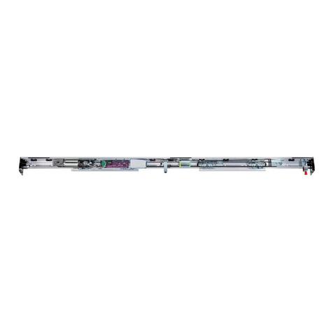
AUTOMATIC DOOR A140 AIR H100 - H140
1 DESCRIPTION
The FAAC series A140 AIR systems automatically activate,
manage and control the operation of single-leaf or two-leaf
sliding doors.
The FAAC series A140 AIR automated systems are supplied
completely assembled, wired and tested in the configuration
requested by the customer, using the appropriate order form, or
in kits to be assembled by the installation technician.
An automation cross beam (fig.1) consists of the following
parts:
Support profile (fig.1 ref.)
This is the profile used when the cross beam can be completely
secured to a load bearing structure.
Motor unit (fig. 1 ref.)
The 24= motor has an encoder and a leaf locking system
(accessory).
The Electronics Module includes:
Control unit (fig. 1 ref. )
When powered, the control unit with microprocessor, initialises
the door’s operational parameters.
Power feed unit (fig. 1 ref. )
The power feed unit, directly connected to the control unit,
supplies the voltage values required to correctly power the
automated system.
Leaf support carriages (fig.1 ref.)
The carriages have two wheels with ball bearings, one counter
thrust wheel in the top part, and a screw based system for
adjusting the height of the leaves.
Drive belt (fig. 1 ref. )
Transmission pulley unit (fig. 1 ref. )
1.1 ACCESSORIES SUPPLIED WITH THE CROSS BEAM
These parts are assembled on the cross beam.
Closing housings (fig. 1 ref. )
This is the aluminium profile enabling closure of the automated
system. The side panels (fig.1 ref.) completely close the
system.
Motor lock unit (fig. 1 ref. )
The motor lock unit guarantees mechanical locking of the door
while the leaves are closed. The motor lock unit can be used for
single and double leaves.
The motor lock unit is supplied with the internal release device
(Fig.1 ref.) used for emergency opening if needed. It is also
designed for installation of the external release (optional) if
required. The motor lock unit acts directly on the motor, locking
it mechanically.
Supervision of motor lock
It controls if the motor lock unit is operating correctly and verifies
if the door is actually closed. If necessary, the system is designed
for remotely activating an indicator light or buzzer/siren.
Emergency battery (fig. 1 ref. )
In the event of a mains power cut, the battery kit enables the
automated system to operate until its charge is exhausted. The
battery condition test is performed continuously by the control
unit.
fig. 1

3
115V/230V~
RX
TX
ENGLISH
MODEL A140 AIR A140 AIR 2
No. of leaves 1 2
Max leaf weight 200 Kg 120 + 120 Kg
Transit space (VP) 700 ÷ 3000 mm 800 ÷ 3000 mm
Max thickness of framed leaf 65 mm
Use frequency 100 %
Protection class IP 23 (for indoor use)
Operating ambient temperature -20°C ÷ +55°C
Power supply 115V/230 V~ 50/60 Hz
Max absorbed power 100 W
Beam length Vp x 2 +100 mm
Drive unit 24 Vdc with encoder
Opening speed adjustment (load free) 5 ÷ 70 cm/sec. 10 ÷ 140 cm/sec.
Closing speed adjustment (load free) 5 ÷ 70 cm/sec. 10 ÷ 140 cm/sec.
Partial opening adjustment 10% ÷ 90% of total opening
Pause time adjustment 0 ÷ 30 sec.
Night pause time adjustment 0 ÷ 240 sec.
Static force adjustment automatic
Anti-crushing device active at opening/closing
Failsafe on photocells Yes (can be activated by programming)
2 ELECTRICAL PREPARATIONS
3 TECHNICAL SPECIFICATIONS
Route the electrical cables for connecting the accessories and
electrical power supply as shown in Fig. 2.
N° DESCRIPTION CABLES
External radar 4x0.25mm²
Internal radar 4x0.25mm²
Photocell transmitter 2x0.25mm²
Photocell receiver 3x0.25mm²
SD-Keeper / SDK-Light 2x0.5mm² max 50 m
Key operated switch
for locking SD-Keeper /
SDK-Light (future accessory)
2x0.5mm²
Control push-buttons
Emerg/Key/Reset
2x0.5mm²
Power supply
115/230V
~
2x1.5mm² + earth
1.2 DOOR FRAME ACCESSORIES
To facilitate the door profile to adapt to the carriages and to enable correct finish of the installation, FAAC offers the following
series of articles:
Pair of sliding blocks (fig. 24-25 ref. )
Supplied as a pair, they can be secured on a wall (or on the fixed leaf) or directly on the floor.
Lower guide profile (fig. 24-25 ref. )
For adapting the lower profile of the leaf to the above sliding blocks.
Brush for lower guide profile (fig. 24-25 ref. )
Completes the on-floor guide system.
Leaf fitting profile (fig. 17-18 ref. )
Adapts the leaf’s top profile to the carriage fittings.
Pair of lower sliding blocks for glass panel leaf
They enable the glass leaves to slide
4 CROSS BEAM CONFIGURATION
To suitably position the cross beam components, refer to the
dimensions in figures 7, 8, and 9.
fig. 2

4
ENGLISH
SUPPORT PROFILE
HOUSING PROFILE H100 and H140
LEAF FITTING PROFILE
LOWER GUIDE PROFILE
GRIPPER FOR GLASS LEAF
LOWER SLIDING BLOCK FOR GLASS LEAF
CABLE ROUTING COMPARTMENT
FREE-STANDING PLATE
FREE-STANDING PROFILE
TRANSOM PROFILE
PROFILES KEY
fig. 3
H140 LEAF CARRIAGE SPACER

5
A140 AIR H100 - H140
ENGLISH
fig. 4

6
ENGLISH
fig. 5
A140 AIR H100
- H140
glass leaf

7
ENGLISH
A140 AIR H140 with door carriage spacer
fig. 6

8
I
Motore
82,5
Lt
B
Vp
CI
82,5
Lt
B
Vp
Vp Lt B I C D
700 1500 465 915 432 2000
800 1700 565 1015 532 2200
900 1900 665 1115 632 2400
1000 2100 765 1215 732 2600
1100 2300 865 1315 832 2800
1200 2500 965 1415 932 3000
1300 2700 1065 1515 1032 3200
1400 2900 1165 1615 1132 3400
1500 3100 1265 1715 1232 3600
1600 3300 1365 1815 1332 3800
1700 3500 1465 1915 1432 4000
1800 3700 1565 2015 1532 4200
Vp Lt B I C D
1900 3900 1665 2115 1632 4400
2000 4100 1765 2215 1732 4600
2100 4300 1865 2315 1832 4800
2200 4500 1965 2415 1932 5000
2300 4700 2065 2515 2032 5200
2400 4900 2165 2615 2132 5400
2500 5100 2265 2715 2232 5600
2600 5300 2365 2815 2332 5800
2700 5500 2465 2915 2432 6000
2800 5700 2565 3015 2532 6200
2900 5900 2665 3115 2632 6400
3000 6100 2765 3215 2732 6600
Lt = Vp X 2 + 100
ENGLISH
Motor Control
board Power feeder Transmission
pulley
fig. 7
B = Securing distance of carriages on sliding leaf
C = Motor position dimension
D = Transmission belt length
I = Between centres distance: motor/transmission
unit
Lt = Cross beam length
Vp = Transit space
100 = mm of overlap between leaves (see
par.1.1B)
A140 AIR Single Leaf, Right hand opening
Emergency
batteries

9
Lt
B
CI
Vp
82,5
Vp Lt B I C D
700 1500 465 915 432 2000
800 1700 565 1015 532 2200
900 1900 665 1115 632 2400
1000 2100 765 1215 732 2600
1100 2300 865 1315 832 2800
1200 2500 965 1415 932 3000
1300 2700 1065 1515 1032 3200
1400 2900 1165 1615 1132 3400
1500 3100 1265 1715 1232 3600
1600 3300 1365 1815 1332 3800
1700 3500 1465 1915 1432 4000
1800 3700 1565 2015 1532 4200
Vp Lt B I C D
1900 3900 1665 2115 1632 4400
2000 4100 1765 2215 1732 4600
2100 4300 1865 2315 1832 4800
2200 4500 1965 2415 1932 5000
2300 4700 2065 2515 2032 5200
2400 4900 2165 2615 2132 5400
2500 5100 2265 2715 2232 5600
2600 5300 2365 2815 2332 5800
2700 5500 2465 2915 2432 6000
2800 5700 2565 3015 2532 6200
2900 5900 2665 3115 2632 6400
3000 6100 2765 3215 2732 6600
Lt = Vp X 2 + 100
ENGLISH
Motor Control
board
Power feeder Transmission
pulley
fig. 8
B = Securing distance of carriages on sliding leaf
C = Motor position dimension
D = Transmission belt length
I = Between centres distance: motor/transmission
unit
Lt = Cross beam length
Vp = Transit space
100 = mm of overlap between leaves (see
par.1.1B)
A140 AIR Single Leaf, Left hand opening
Emergency
batteries

10
82,5
Lt
Vp
B
3030
B82,5
CI
Vp Lt B I C D
800 1700 165 1365 167,5 2900
900 1900 215 1465 217,5 3100
1000 2100 265 1565 267,5 3300
1100 2300 315 1665 317,5 3500
1200 2500 365 1765 367,5 3700
1300 2700 415 1865 417,5 3900
1400 2900 465 1965 467,5 4100
1500 3100 515 2065 517,5 4300
1600 3300 565 2165 567,5 4500
1700 3500 615 2265 617,5 4700
1800 3700 665 2365 667,5 4900
Vp Lt B I C D
1900 3900 715 2465 717,5 5100
2000 4100 765 2565 767,5 5300
2100 4300 815 2665 817,5 5500
2200 4500 865 2765 867,5 5700
2300 4700 915 2865 917,5 5900
2400 4900 965 2965 967,5 6100
2500 5100 1015 3065 1017,5 6300
2600 5300 1065 3165 1067,5 6500
2700 5500 1115 3265 1117,5 6700
2800 5700 1165 3365 1167,5 6900
2900 5900 1215 3465 1217,5 7100
3000 6100 1265 3565 1267,5 7300
Lt = Vp X 2 + 100
ENGLISH
B = Securing distance of carriages on sliding leaf
C = Motor position dimension
D = Transmission belt length
I = Between centres distance: motor/transmission
unit
Lt = Cross beam length
Vp = Transit space
100 = mm of overlap between leaves (see
par.1.1B)
Motor
Control
board Power feeder Transmission
pulley
fig. 9
A140 AIR Double Leaf
Emergency
batteries

11
Lt
50 50
Vp
ENGLISH
A. ASSEMBLY OF IN-KIT AUTOMATED SYSTEMS
1A PREPARING THE SUPPORT PROFILE
Support profiles are available in two sizes:
4300 mm or 6100 mm.
Cut the support profile to measure using the following formula:
LT = Vp x 2 + 100
Where:
• Lt is the length of the support profile
• VP is the transit space
• 100 are the overlap millimeters between the leaves (50 + 50)
This section describes the assembly of the in-kit automated systems. After you have prepared the necessary profiles, we advise you
to assemble and install at the same time.
Automation free-standing refer to Chapter 21
fig. 10
1.1A SUPPORT PROFILE - SECURING ON WALL
Define the exact height position of the support profile, considering
the dimensions of fig. 4 and fig. 6; for doors with glass leaves,
refer to fig.5.
The cross beam must be fastened parallel to the
floor.
Initially fix the support profile on a vertical slot at one end, and
on a horizontal slot at the other end (using M8 screws and
appropriate expansion plugs which are not supplied) and level
parallel to the floor. Fasten centrally, lifting the support profile with
force to align the three securing points. Carry out the remaining
fastenings.fig.11

12
200200
30 30 30
37,5
80
ENGLISH
fig. 12
fig. 13
1.2A FITTING THE ELECTRONICS MODULE ROD
The mechanical stops are 2 for single leaf and to 4 and double
leaf . Insert the sliding guide on the profile fig 13-and insert
sideways the mechanical stop fig 13-.
Then secure it with the 2 Allen screws fig.13 and fig.14-.
1.3A ASSEMBLING THE SLIDING GUIDE
Important : the rod with tie-rods be fitted before securing
the support profile to the wall.
If the rod was not fitted, you can fit the small plates with the
relevant screws instead of it
Insert the rod with tie-rods sideways on the support profile
in order to fit the electronics module fig.12
Important : The central and side mechanical stops must
be fitted sideways, after the sliding guide, as first element
of the A140 AIR door.
fig. 11

13
ENGLISH
2A PREPARING THE LEAVES
Prepare the leaves as described below.
1. Secure to the leaf, the leaf fitting profile cut to the same
length, and secure it with adequate screws on the upper
part (fig. 17).
2. Place two carriages on each leaf making use of the supplied
plates and screws; then mount the leaf and carriage unit on
the sliding profile, as shown in fig. 18 .
3. Secure the carriages on the leaf, using the dimensions in
figure 9 for the double leaf, and fig. 7-8 for the single leaf.
Tighten the carriage securing screws.
4. Cut the lower guide profile to the same length as the leaf
and secure with adequate screws on the lower part.
5. If specified, insert the brush in the seat of the sliding profile
Fig. 19 ref. .
Use an Allen key M5.
To lock the 2 Allen screws of the side and central mechanical
stops, use an Allen key M5( fig.15 and fig.16 ).
fig. 18
fig. 17
fig. 19
fig. 15 fig. 16
fig. 14
Important : place the side and central mechanical stops
correctly, abutting with the profile, before
blocking them (fig.14
).

14
ENGLISH
2A-1 PREPARING THE LEAVES – Alternative method to fit heavy leaves
Prepare the leaves as described below:
Disassemble the carriage by withdrawing the upper and lower plate of the carriage fig.20 ref.
and removing the 2 fastening screws M6 fig.20 ref.
.
Then, fit the upper plate of the carriage on the sliding profile fig 21 ref.
and fit the lower plate of the
carriage in the leaf fitting profile fig 21 ref.
. Then secure using the bolts fig 21 ref.
.
fig.20
fig.21

15
ENGLISH
Lift the leaf – carriage lower plate assembled unit to the height of the carriage upper plate. fig 22 ref.
Secure the 2 parts of the carriage using the 2 screws M6 fig 22 ref.
Adjust the carriages on the leaf observing the dimensions indicated in fig. 9 for double leaf and fig. 7-8 for single
leaf versions.
Tighten the screws securing the carriages fig 23.
fig.22
fig.23

16
ENGLISH
The carriages allow leaf height adjustment of ± 7.5 mm.
Adjustment procedure:
• Slightly loosen the two screws M6 - fig.28 ref..
• Turn the screw (fig.27 ref.5 clockwise to raise the leaves or anti-
clockwise to lower them.
• Tighten the two screws M6 you had loosened
4.1A LEAF HEIGHT ADJUSTMENT
4A ADJUSTING THE LEAVES
When you have prepared the leaves, install them on the support
profile.
The carriages have two sliding wheels (Fig.28 ref. ) and a
counter-thrust wheel (Fig.28 ref. )
Two slots are provided on the base of the carriages. These slots
enable leaf depth adjustment (Fig.28 ref. )
4.2A LEAF DEPTH ADJUSTMENT
To adjust the depth of the leaves, loosen the
2 bolts
2 bolts as shown in
Fig.29 rif.
.
Move the leaf on the carriage slot as you require and tighten the
2 bolts.
Make sure that the leaves are parallel with respect
to the support profile.
3A INSTALLING THE LOWER SLIDING BLOCKS
The lower sliding blocks are designed for securing to a wall (or
fixed leaf) or to the floor.
Assemble the sliding blocks, referring to the dimensions in figures
24 and 25.
On-wall securing (or on fixed leaf):
• Secure the sliding blocks as shown in Fig. 26 ref., using
adequate screws.
Securing on the floor
• Directly secure the sliding block to the floor, as shown in Fig. 26
ref. , using adequate expansion plugs and screws.
fig. 26
fig. 24
fig. 25
fig. 28 fig. 29
fig. 27

17
ENGLISH
4.3A ADJUSTING THE COUNTER-THRUST WHEEL
The carriages have a counter-thrust wheel which prevents them
from coming out of their seat.
The wheel must be adjusted so that it does not press on
the support profile, to thus avoid increased friction.
Counter-thrust wheel adjustment procedure:
• Loosen the
screw M6 (Fig.30 ref.1).
•
Adjust the height of the wheel support, making it come
as close as possible to the main profile without touching it
(Fig.30 ref.2).
(Fig.30 ref.2).
•
When you have adjusted the wheel’s height, tighten the screw
M6
M6 (Fig. 30 ref. ).
If necessary, use a shim of about 0.5 mm, placing it between the
wheel and the main profile, removing it when you have finished
the adjustment.
Move the leaves by hand and check if the counter-thrust wheel
is free to move without grazing.
6 REGOLAZIONE ARRESTI MECCANICI5A ADJUSTING THE OPENING MECHANICAL STOPS
The automatic door is supplied with the opening mechanical
stops installed on the support profile. As the leaves open, make
sure that the carriages come into contact with the mechanical
stops. If adjustments are required, proceed as follow:
• Loosen the
Allen screws
Allen screws of the mechanical stops (Fig. 31 ref.
) and take them to the ends of the support profile.
• Take the leaf or leaves into opening position (fig. 32), take
the mechanical stop near to the carriage until the two parts
touch and tighten the
Allen screws
Allen screws (Fig32 ref. ).
fig. 30
fig. 32
fig. 31

18
==
ENGLISH
6A ADJUSTING THE CLOSING MECHANICAL STOPS
(DOUBLE LEAF)
The automatic door is supplied with the closing mechanical stops
installed on the mid-point of the support profile. If the door centre
requires adjustment, proceed as follows:
• Check if the mechanical stops are at the centre of the
profile.
• Take the leaf or leaves into the closing position.
• Loosen
the 2 bolts
the 2 bolts of the carriages (Fig.33 ref.).
• Take the carriage close to the contact point until the two
touch.
•
Tighten again the 2 bolts securing the carriages.
6.1A ADJUSTING THE CLOSING MECHANICAL STOPS (SINGLE
LEAF)
The automatic door is supplied with the closing mechanical stops
installed on the support profile. As the leaves close, make sure that
the carriages come into contact with the mechanical stops.
fig. 33
This manual suits for next models
4
Table of contents
Other FAAC Door Opening System manuals
Popular Door Opening System manuals by other brands

Brinsea
Brinsea ChickSafe CS020 Installation and operating instructions

Ditec Entrematic
Ditec Entrematic PASAA2 manual

Raynor
Raynor ControlHoist CMT Installation instructions manual

Benninca
Benninca SAM manual

MANTION SMT
MANTION SMT WIBAT LINTEAU installation instructions

DITEC
DITEC entrematic HA8-LP Installation instructions manual

Allegion
Allegion LCN 2210 Series installation instructions

RIB
RIB TOUCH Wi-Fi manual

Command access
Command access MLRK1 Series installation instructions

MAGNASPHERE
MAGNASPHERE HSS Series installation instructions

Synergy Hardware
Synergy Hardware S150 Series Fixing instructions

Allegion
Allegion LCN 1461 Series quick start guide