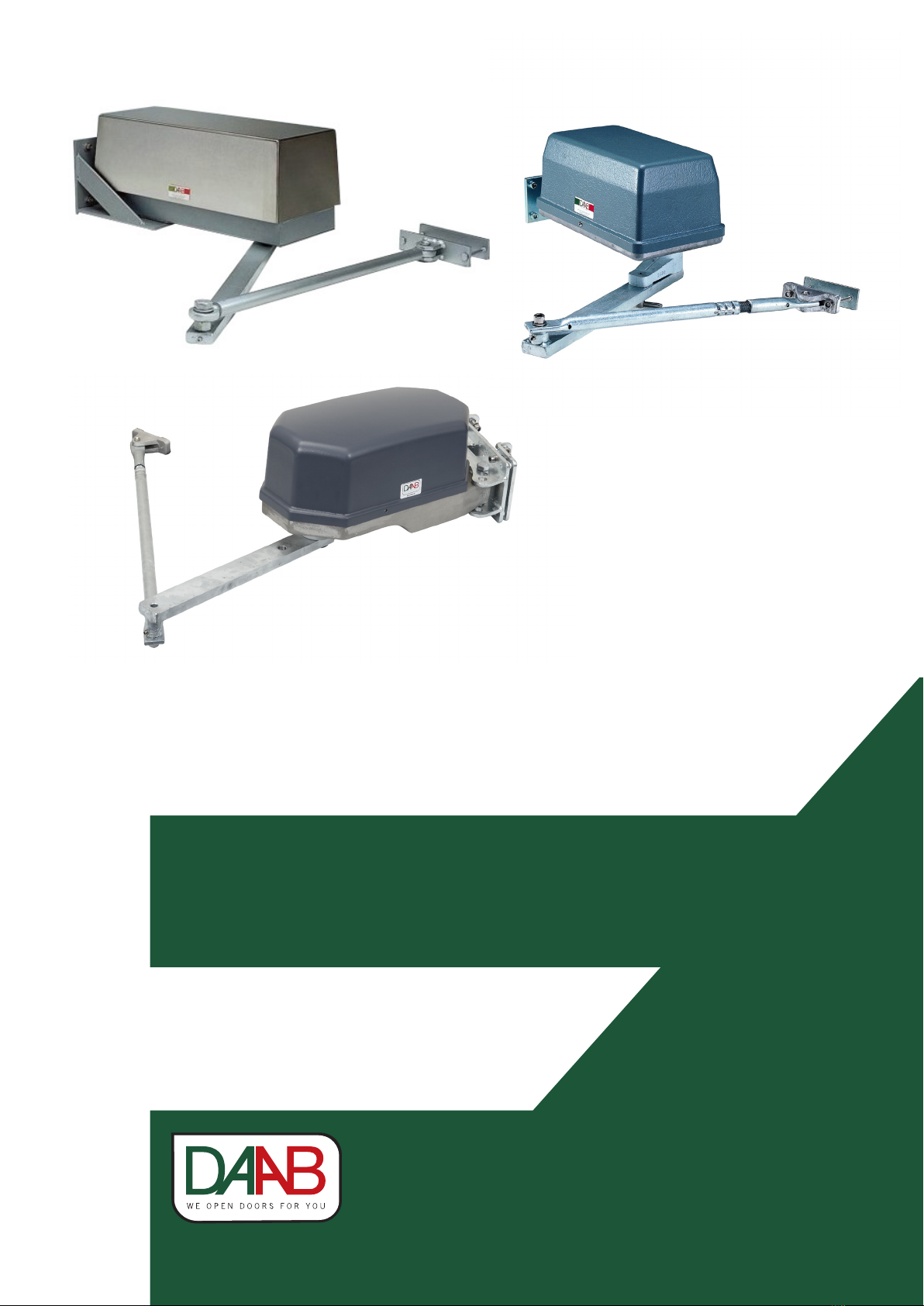
INSTRUCTION MANUAL MT, MA2, MK2, M10 DRIVE UNIT
2
Innehåll
EU Declaration of incorporation...............................3
Safety ........................................................................4
General ....................................................................4
Packing, transport and unpacking...........................4
General ....................................................................4
Introduction ..............................................................5
Intended use ............................................................5
Machine marking .....................................................5
Manufacturer ...........................................................5
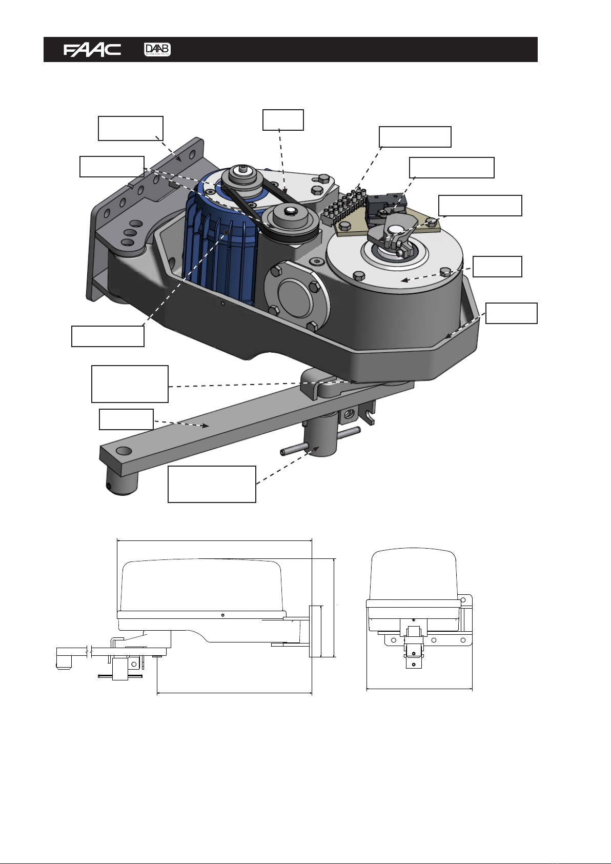
Drive unit MA2/MK2...................................................6
Function description ................................................6
Design and function .............................................6
Dimensions...........................................................6
Technical specification.............................................7
Electric motors......................................................7
Gears ....................................................................7
Installation and commissioning...............................7
General installation ..............................................7
Side installation.......................................................8
Mounting plate .....................................................8
Drive arm..............................................................8
Gate mounting and link arm.................................9
Top mounting ...........................................................9
Bracket & mounting plate.....................................9
Drive arm............................................................10
Gate mounting....................................................10
Link arm .............................................................10
Top mounting with limited lateral space................11
Bracket & mounting plate...................................11
Drive arm............................................................11
Gate mounting....................................................11
Mounting plate for the swing arm bracket..........12
Link arm .............................................................13
Wing mounting.......................................................14
Bracket & mounting plate...................................14
Drive arm............................................................14
Installing the drive unit .........................................15
Drive unit MT ...........................................................16
Function description ..............................................16
Design and function ...........................................16
Dimensions.........................................................16
Technical specification...........................................17
Electric motors....................................................17
Gears ..................................................................17
Installation and commissioning.............................17
General installation ............................................17
Side installation.....................................................18
Mounting plate ...................................................18
Drive arm............................................................18
Gate mounting and link arm...............................19
Top mounting .........................................................20
Bracket & mounting plate...................................20
Drive arm............................................................20
Gate mounting....................................................20
Link arm .............................................................21
Top mounting with limited lateral space................22
Bracket & mounting plate...................................22
Drive arm............................................................22
Gate mounting....................................................22
Mounting plate for the swing arm bracket..........22
Link arm .............................................................23
Adjusting the drive unit .........................................25
Disengagement......................................................25
Quick release ......................................................25
Release handle ...................................................25
Electrical connection..............................................26
General ..................................................................26
Engaging the electric motor...................................26
Limit positions .......................................................27
Maintenance and service........................................27
General ..................................................................27
Lubrication.............................................................27
Oil filled gearbox.................................................27
Open gearbox......................................................28
Spare parts..............................................................28
Fault search............................................................28
In the event of a blockage......................................28
In the event of a collision.......................................28
The motor is running but the gate is not moving ...28