QUICK GUIDE DAAB CONTROL UNIT EP105
2Quick guide for commissioning of swing gates, EP105
Quick guide for commissioning of swing gates
• COUTION
The unit may only be connected by a qualied electrician, who accepts responsibility for ensuring that the electric
connections have been carried out in accordance with the applicable standards and this instruction manual. Always
disconnect the power supply when work is carried out in the control cabinet. Anyone commissioning the EP105 must have
documented familiarity with and understanding of its functions, as well as experience of commissioning control systems for
the application to be used.
For complete instructions refer to instruction manual for EP105 as well as other documentation included in the delivery.
• Conditions
Electrical installation has been carried out and drive units are disconnected. Commission one drive unit at a time only and
start with drive unit 1. The supply voltage in C2020 is set to 0, 3x400V with neutral The limit switch is of the encoder type.
The display channel C999 is set to 2 The indications for safety edge are unlit. The indications for photocell, stop circuit and
24V are lit green.
• Commissioning of drive unit 1
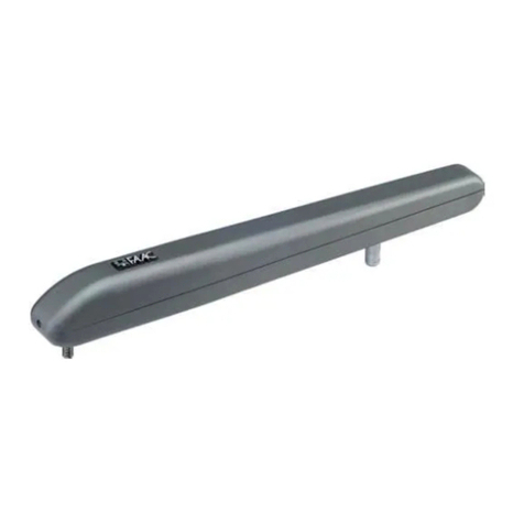
Direction of movement: Start L001 to 4, hold-to-run without limits. Check that the motor arm attachment is running in the
right direction by pressing the OPEN or CLOSE buttons on the automatic control unit. For change of direction of rotation,
see section on Connection in EP105 Instruction Manual.
Open and closed position: Connect the gate half to drive unit 1 and enter the positions for open and closed After this,
L001 is set to 1, encoder
L110=1, Motor 1 Left position L120=2; Motor 2 Right position
L113, Closed position
L112, Open position
L111, Position readout
Motor protection: Read the motor current during operation in C251 and enter this value in C252 for opening and in C253
for closing. E201 means that the entered value is set too low. E206 means that the entered value is set too high.
Load guard: Set C999 to 3. In a hinged gate application personal protection is not normally required, and C230 is set to
0.00. Set C033 to 3, pulse to activate the load guard. After the load guard has tripped, the indication M1 ashes and the
message n071 or n072 is shown on the display and in the error code list in C903. Check that the setting in the load guard
in C232 and C233 is just high enough not to cause material damage, but at the time is so high that it is guaranteed to open
depending on weather conditions and mechanical changes.
Safety edges: Check the safety edges on gate half 1 by pressing on the safety edges during movement. Note that safety
edge function in opening is closed in C131. In activated safety edge during closing, the gate must reverse to the fully open
position, while in opening it must reverse to closed position during the time in C494. Flashing indication for SE.C1 or
SE.O1 means tthat the safety edge has been activated, but is now disabled.

