950N 6 732708 - Rev. F
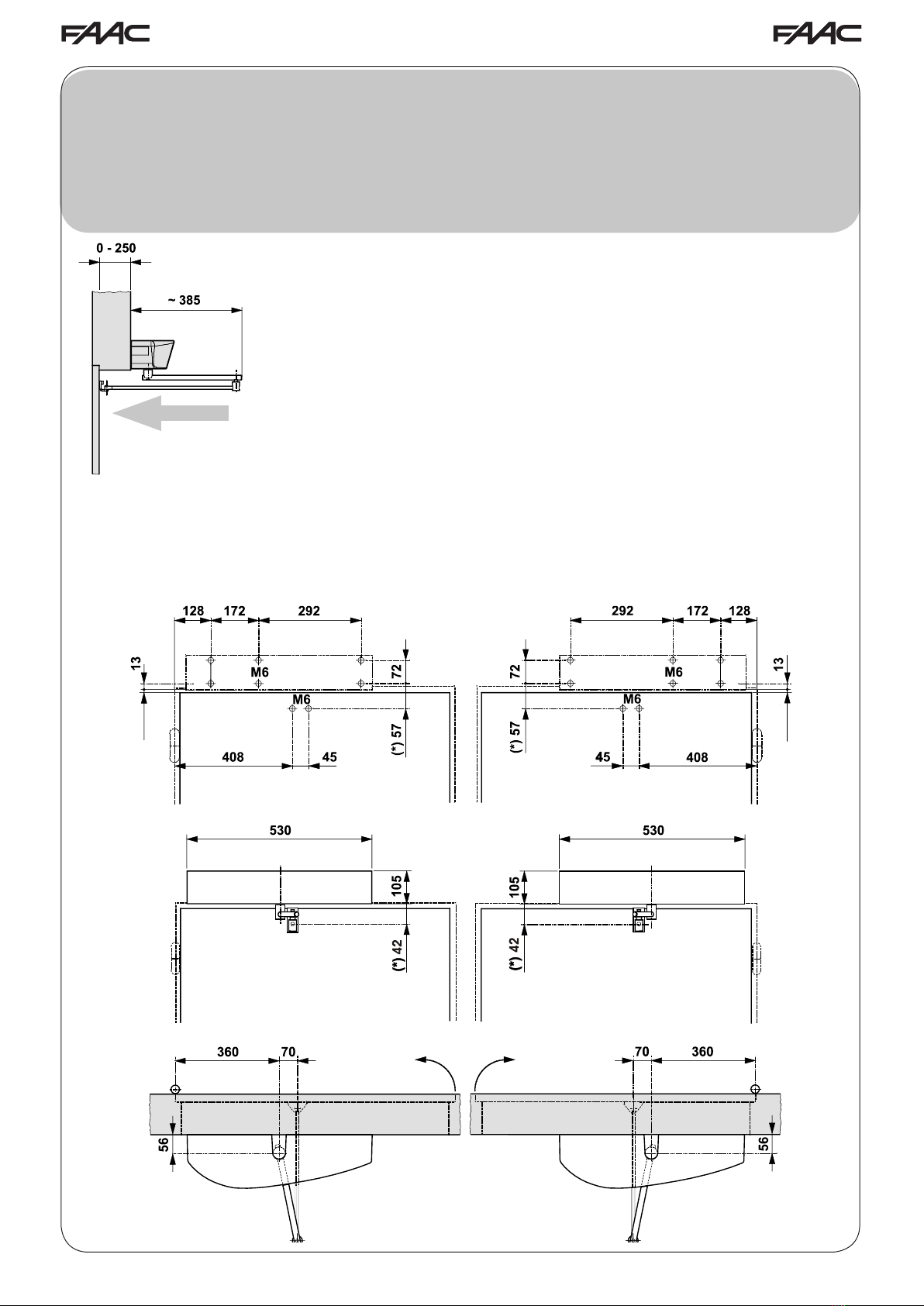
TAVOLA D: BRACCIO A PATTINO L=330 mm CON MONTAGGIO OPERATORE SULL’ARCHITRAVE
TABLE D: SLIDING ARM L=330 mm WITH OPERATOR INSTALLATION ON THE ARCHITRAVE
TABLE D: BRAS À PATIN L=330 mm AVEC MONTAGE DE L’OPÉRATEUR SUR LE LINTEAU
LÁMINA D: BRAZO DE PATÍN L=330 mm CON MONTAJE DEL OPERADOR EN EL DINTEL
ÜBERSICHT D: GLEITKUFENARM L = 330 mm MIT MONTAGE DES ANTRIEBS AM STURZ
TEKENING D: ARM MET GLIJSCHOEN L=330 mm MET MONTAGE AANDRIJVING OP DE BOVENDORPEL
BILD D: GLIDARM L = 330 mm MED DÖRRÖPPNAREN MONTERAD PÅ KARMÖVERSTYCKET
OPEN
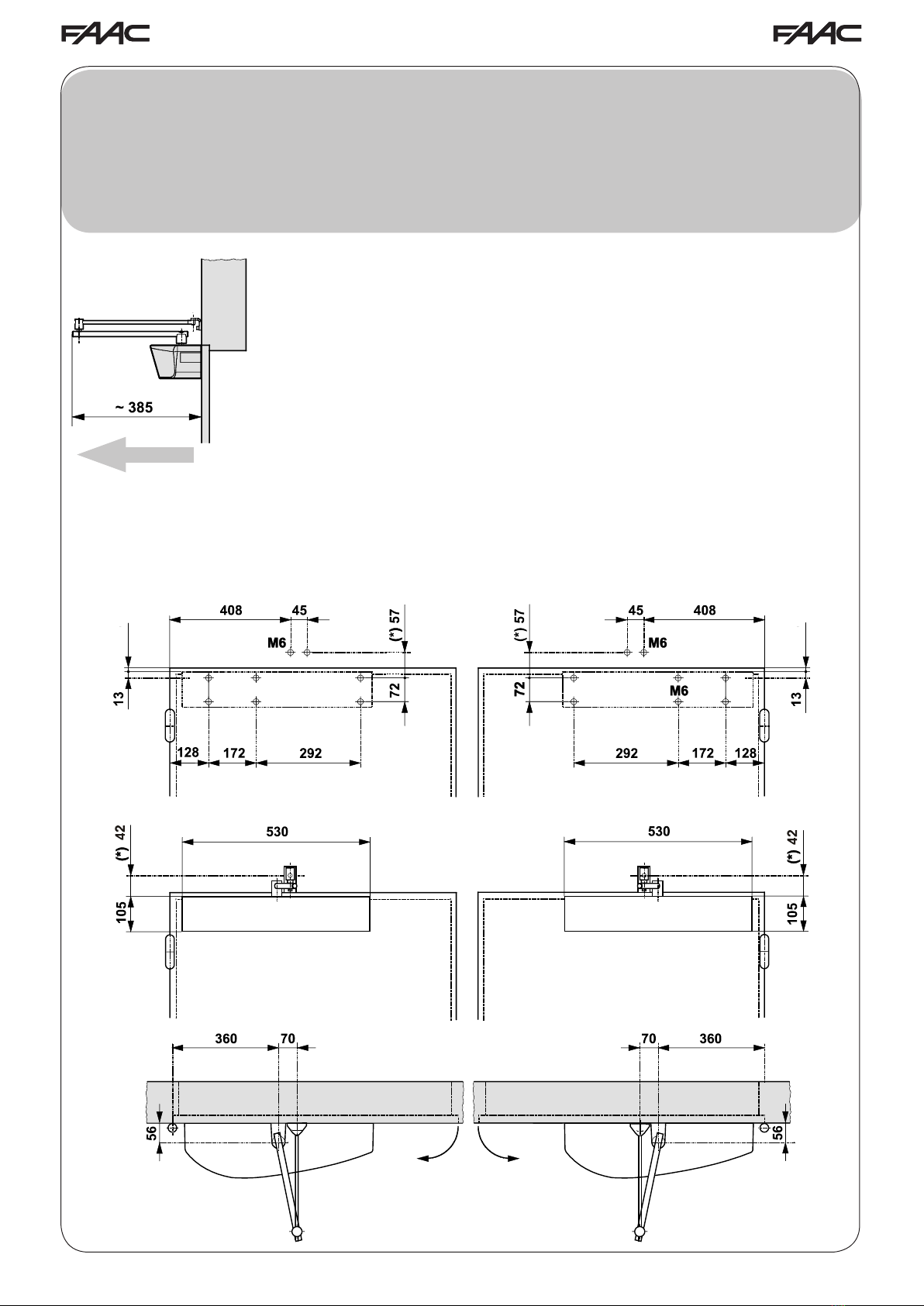
* Quota con albero standard 20 mm. Nel caso fosse necessario aumentare la distanza tra l’operatore ed il braccio,
utilizzare le prolunghe opzionali ( Quota con albero 50 mm = 107mm. - Quota con albero 80 mm = 137 mm)
* Standard shaft dimension 20 mm. Should it become necessary to increase the distance between the operator
and the arm, use the optional extensions (dimension with 50 mm shaft = 107 mm - with 80 mm shaft = 137 mm)
* Cote avec arbre standard de 20 mm. S’il est nécessaire d’augmenter la distance entre l’opérateur et le bras,
utiliser les rallonges en option (Cote avec arbre de 50 mm = 107mm. - Cote avec arbre de 80 mm = 137 mm)
* Cota con árbol estándar 20 mm. Si fuera necesario aumentar la distancia entre el operador y el brazo, utilizar
los alargues opcionales (Cota con árbol 50 mm = 107mm. - Cota con árbol 80 mm = 137 mm)
* Maß mit Standardwelle 20 mm. Wenn der Abstand zwischen dem Antrieb und dem Arm erhöht werden muss,
die optionalen Verlängerungen verwenden (Maß mit 50-mm-Welle = 107 mm; Maß mit 80-mm-Welle = 137 mm)
* Afstand met standaardas 20 mm. Indien de afstand tussen de aandrijving en de arm groter moet zijn, gebruik
dan de optionele verlengstukken (Afstand met as 50 mm = 107mm. - Afstand met as 80 mm = 137 mm)
* Mått med standardaxel 20 mm. Om det är nödvändigt att öka avståndet mellan dörröppnaren och armen,
använd de extra förlängningarna. (Mått med axel på 50 mm = 107mm - mått med axel 80 mm = 137 mm.)
gh
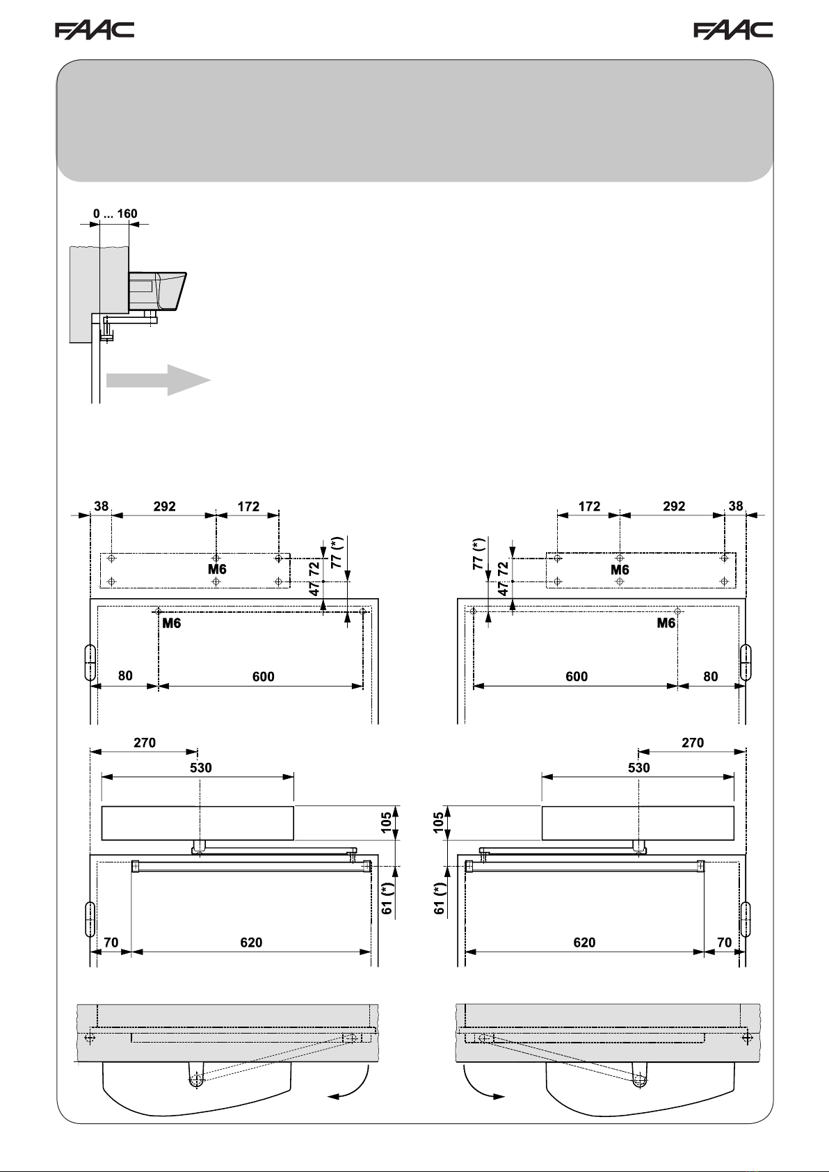
BRACCIO ARTICOLATO (B=250-160 mm)- ARTICULATED PUSH ARM (B=250-160 mm) -
BRAS ARTICULÉ À POUSSÉE (B=250-160 mm) - BRAZO ARTICULADO DE EMPUJE (B=250-160 mm)-
DRUCKGELENKARM (B=250-160 mm) - KNIKARM MET DUWSYSTEEM (B=250-160 mm) - LEDAD ARM (B = 250-160 mm)
- LUNGHEZZA ANTA - LEAF LENGTH
- LONGUEUR VANTAIL -
FLÜGELLÄNGE
- LONGITUD HOJA - LENGTE VLEUGEL
DÖRRBLADETS LÄNGD ( mm )
PESO PORTA - LEAF WEIGHT - POIDS VANTAIL -
FLÜGELGEWICHT - PESO DE LA HOJA - GEWICHT VLEUGEL -
DÖRRBLADETS VIKT (Kg)
20 40 80 100 120 140 160 180 200 220 240 260
700 853222111111
800 7 4 2 2 1 1 1 1 1
900 6 3 2 1 1 1 1
1000 5 3 1 1 1
1100 4 2 1 1
1200 4 2 1
1300 3 2
1400 3 1
-Velocità apertura e chiusura da impostare tramite KP CONTROLLER
- Opening and closing speed to be set via KP CONTROLLER
- Vitesse d’ouverture et de fermeture à régler par KP CONTROLLER
- Über den KP CONTROLLER einzugebende Öffnungs- und Schließungsgeschwindigkeit
- Velocidad de apertura y cierre para congurar mediante KP CONTROLLER
- Snelheid openen en sluiten in te stellen via KP CONTROLLER
-Öppnings- och stängningshastighet ställs in med programmeringsenheten KP CONTROLLER
BRACCIO ARTICOLATO ( B=0 mm-) ARTICULATED PUSH ARM (B=0 mm) -
BRAS ARTICULÉ À POUSSÉE (B= 0 mm) - BRAZO ARTICULADO DE EMPUJE (B= 0 mm) -
DRUCKGELENKARM (B= 0 mm) - KNIKARM MET DUWSYSTEEM (B= 0 mm) - LEDAD ARM (B = 0 mm)
- LUNGHEZZA ANTA - LEAF LENGTH
- LONGUEUR VANTAIL -
FLÜGELLÄNGE
- LONGITUD HOJA - LENGTE VLEUGEL
DÖRRBLADETS LÄNGD ( mm )
PESO PORTA - LEAF WEIGHT - POIDS VANTAIL -
FLÜGELGEWICHT - PESO DE LA HOJA - GEWICHT VLEUGEL -
DÖRRBLADETS VIKT (Kg)
20 40 80 100 120 140 160 180 200 220 240 260
700 8 5 3 2 2 2 1 1 1 1 1 1
800 7 4 2 2 1 1 1 1 1
900 6 3 2 1 1 1 1
1000 5 3 1 1 1
1100 4 2 1 1
1200 4 2 1
1300 3 2
1400 3 1
-Velocità apertura e chiusura da impostare tramite KP CONTROLLER
- Opening and closing speed to be set via KP CONTROLLER
- Vitesse d’ouverture et de fermeture à régler par KP CONTROLLER
- Über den KP CONTROLLER einzugebende Öffnungs- und Schließungsgeschwindigkeit
- Velocidad de apertura y cierre para congurar mediante KP CONTROLLER
- Snelheid openen en sluiten in te stellen via KP CONTROLLER
-Öppnings- och stängningshastighet ställs in med programmeringsenheten KP CONTROLLER