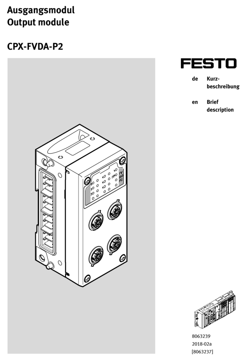
manuals.online logo
Brands
  1. Home
  2. •
  3. Brands
  4. •
  5. Festo
  6. •
  7. Control Unit
  8. •
  9. Festo HMP AD Series User manual

Festo HMP AD Series User manual

Bedienungsanleitung
Pneumatisch-elektrisches
Abschlußmodul
Typ HMP-...-AD/-EL
Operating instructions
Pneumatic-electric
end module
type HMP-...-AD/-EL
Einbau und Inbetriebnahme
nur von qualifiziertem Fachpersonal,
gemäß Bedienungsanleitung.
Fitting and commissioning to be
carried out by qualified personnel
only in accordance with the operating
instructions.
Es bedeuten/Symbols:
Warnung
Warning, Caution
Hinweis
Note
Recycling
Recycling
Zubehör
Accessories
397 780
0001a D/GB 1
Bedienteile und Anschlüsse Operating parts and
connections
143
256
7
8
9
0
Bild 1/Fig. 1
1
2
3
4
5
6
7
8
9
0
Abschlußdeckel mit 2 Schrauben
M 3 an
9
befestigt
Sichtfenster für LED’s
Bohrungen zur Befestigung des
Abschlußmoduls
Verschlußkappe für Kabel-
austrittsöffnung
Klemmleiste für Sensorenkabel
Gelbe LED’s für Schaltzustandsan-
zeige für sechs mögliche Sensoren
Stecker für Sammelkabel
Steckersockel
Metallträger
Einschubblende
1
2
3
4
5
6
7
8
9
0
End cover fastened at
9
with two
M 3 screws
LED display window
Holes for fastening the end module
End cap for cable exit
Terminal strip for sensor cables
Yellow LEDs for switching status
display of six possible sensors
Plug for common cable
Plug base
Metal support
Slide-in screen
1
HMP-...-AD/-EL
0001a D/GB 2
Function and application
The pneumatic-electric end module
HMP-...-AD/-EL is used for grouping to-
gether the following supply lines:
Possible central grouping of
supply lines
HMP-...-AD HMP-...-EL
–pneumatic –pneumatic
–electric
Fig. 2
The electrical connections can be made
with a common cable. The switching
status is indicated by LEDs which are
visible from the outside through a win-
dow
2
. All supply cables have protecti-
ve tubing.
Funktion und Anwendung
Das pneumatisch-elektrische Ab-
schlußmodul HMP-...-AD/-EL dient be-
stimmungsgemäß zur zentralen Zufüh-
rung folgender Versorgungsleitungen:
Mögliche zentrale Zuführung von
Versorgungsleitungen
HMP-...-AD HMP-...-EL
–pneumatisch –pneumatisch
–elektrisch
Bild 2
Die elektrischen Kabel können an einem
Sammelanschlußverkabelt werden. Der
Schaltzustand von bis zu sechs Senso-
ren wird durch LED’s angezeigt, die
durch die Sichtfenster
2
nach außen
durchscheinen. Sämtliche Versorgungs-
leitungen werden mit Hilfe eines Kabel-
schutzschlauchs abgeführt.
2
Bild 3/Fig. 3
0001a D/GB 3
Conditions of use
These general conditions for the correct
and safe use of the product must be ob-
served at all times.
•Compare the specified values with
your application.
Please observe the specified limits
(e.g. for moments and temperatures).
•The product must be used in its orig-
inal state. Unauthorized modification
is not permitted.
Fitting
Mechanical
•Fasten the end module as follows:
Voraussetzungen für den
Produkteinsatz
Allgemeine, stets zu beachtende Hin-
weise für den ordnungsgemäßen und si-
cheren Einsatz des Produkts:
•Vergleichen Sie die angegebenen
Grenzwerte mit Ihrem Einsatzfall.
Die zulässigen Grenzwerte, z.B. für
Momente und Temperaturen dürfen
nicht überschritten werden.
•Verwenden Sie das Produkt im Origi-
nalzustand ohne jegliche eigenmäch-
tige Veränderung.
Einbau
mechanisch
•Befestigen Sie das Abschlußmodul
wie folgt:
C%mbar
Bild 4/Fig. 4
3
4
HMP-...-AD/-EL
0001a D/GB 4
1. Unscrew the two screws from the end
cover (keep in a safe place).
2. Pull the end cover down from the Me-
tallträger
9
end module.
3. Fasten the metal support to the rear
end cover of linear module HMP-...
with the three M5 screws supplied.
•Fit the protective cable as follows:
1. Select cable exit.
2. Remove the end cap
4
. Do not
remove the slide-in screen
0
.
3. Fasten the screw connector with the
lock nut (see "Accessories").
4. Pass the pneumatic tubing and the
common electric cable (only on HMP-
...-EL) through the screw connector
and the protective tubing (see "Acces-
sories").
5. Plug in the protective tubing.
1. Die zwei Schrauben aus dem Ab-
schlußdeckel drehen (gut verwahren).
2. Abschlußdeckel vom Metallträger
9
herunterziehen.
3. Metallträger mit drei beiliegenden
Schrauben M5 am hinteren Enddeckel
des Linearmoduls HMP-... befestigen.
•Montieren Sie den Kabelschutz-
schlauch wie folgt:
1. Kabelaustrittsöffnung wählen.
2. Verschlußkappe
4
entfernen. Einschub-
blende
0
dabei nicht demontieren.
3. Verschraubung mit Gegenmutter befe-
stigen (siehe Zubehör).
4. Pneumatikschläuche und elektrisches
Sammelkabel (nur bei HMP-...-EL)
durch Verschraubung und Kabel-
schutzschlauch (siehe Zubehör) füh-
ren.
5. Kabelschutzschlauch in Verschraubung
einstecken.
Bild 5/Fig. 5
Bild 6/Fig. 6
0001a D/GB 5
Electrical
•Use only power units which ensure
reliable electrical isolation of the
operating voltages with at least 4 kV
isolation resistance as per
IEC 742/ EN 60742/VDE 0551.
Switch power packs are permitted
providing they ensure reliable
isolation as per EN 60950/VDE 0805.
•Always use sensors with the same
switching output (e.g. only positive-
switching sensors - PNP).
Mixed operation with positive and ne-
gative-switching sensors is not per-
mitted.
Setting the permitted switching output
•Position the jumper
!
as shown in
Fig. 7 for positive-switching sensors
(PNP; factory setting) or negative-
switching sensors (NPN).
elektrisch
•Verwenden Sie nur Netzteile, die
eine sichere elektrische Trennung
der Betriebsspannung nach IEC 742/
EN 60742/VDE 0551 mit mindestens
4 kV Isolationsfestigkeit gewähr-
leisten.
Schaltnetzteile sind zulässig, wenn
sie die sichere Trennung im Sinne
der EN 60950/VDE 0805
gewährleisten.
•Verwenden Sie stets Sensoren mit
dem selben Schaltausgang (z.B. nur
positivschaltende Sensoren - PNP).
Der Mischbetrieb von positiv- und
nullschaltenden Sensoren ist nicht
zulässig.
Zur Einstellung des zulässigen Schalt-
ausgangs:
•Positionieren Sie den Jumper
!
ge-
mäß Bild 7 für positivschaltende Sen-
soren (PNP; Werkseinstellung) oder
nullschaltende Sensoren (NPN).
/
1
/
1
/1/
1/1
Y
Y
YY
!
Bild 7/Fig. 7
HMP-...-AD/-EL
0001a D/GB 6
•Wire the electrical connections as fol-
lows (see Fig. 8 and 9):
1. Connect the terminal strip
5
for the
sensors (check polarity of the sensors).
2. Disconnect the plug for the common
cable
7
from the plug base
8
.
3. Remove approx. 6 mm of insulation
from the cable core.
4. Connect the plug and insert it again.
Do not squeeze the sensor cables.
5. Fix the common cable at the metal sup-
port with a cable binder (strain relief).
•Fasten the end cover with the
screws supplied.
•Verkabeln Sie die elektrischen An-
schlüsse wie folgt (siehe Bild 8 u. 9):
1. Sensoren an der Klemmleiste
5
verka-
beln (auf Polung der Sensoren achten)
2. Stecker für Sammelkabel
7
vom
Steckersockel
8
abziehen.
3. Adern abisolieren (Abisolierlänge:
ca. 6 mm).
4. Stecker verkabeln und wieder auf-
stecken. Sensoradern dabei nicht quet-
schen.
5. Sammelkabel mit Kabelbinder am
Metallträger fixieren (Zugentlastung).
•Befestigen Sie den Abschlußdeckel
mit den beiliegenden Schrauben.
Bild 8/Fig. 8
Bild 9/Fig. 9
Bild 10/Fig. 10
0001a D/GB 7
Inbetriebnahme
•Starten Sie einen Probelauf anhand
der Bedienungsanleitung des Linear-
modul.
•Prüfen Sie im Probelauf, ob folgende
Punkte erfüllt sind:
–LEDs zeigen den geforderten
Schaltzustand an
–Kabelschutzschlauch wird nicht
unzulässig gebogen oder gedehnt
(siehe Technische Daten).
Wartung und Pflege
•Reinigen Sie im Falle von Verschmut-
zungen das HMP-... mit einem wei-
chen Lappen.
Zulässige Reinigungsmedien sind:
–Seifenlauge (max. +60 oC) und
–alle werkstoffschonenden Medien.
Commissioning
•Start a test run with the operating in-
structions with the linear module.
•During the test run, check whether
the following conditions are fulfilled:
–the LEDs show the required
operating status
–the protective tubing must not be
bent or stretched (see "Technical
Specifications").
Care and maintenance
•If the HMP-... is dirty, clean it with a
soft cloth.
Permitted cleaning agents are:
–soap suds (max. +60 oC) and all
–non-abrasive agents.
5
6
HMP-...-AD/-EL
0001a D/GB 8
7Störungsbeseitigung
Störung mögliche Ursache Abhilfe
LED leuchtet nicht –Anschlußfehler
–unzulässige Kabelbiegung beheben
Jumpereinstellung an der HMP-
...-EL entspricht nicht dem
Schalterausgang der Sensoren
Jumper an der HMP-...-EL
gemäß Kapitel ’Einbau
elektrisch’ plazieren
Druckluftversorgung
unterbrochen Kabelschutzschlauch zu stark
gebogen Zul. Mindest-Biegeradius
einhalten (siehe Technische
Daten)
Bild 11
Eliminating faults
Fault Possible causes Remedy
LED does not light up –Connection fault or
–cable is bent Rectify
Jumper setting on HMP-...-EL
does not correspond to switching
output on sensors.
Position jumper on HMP-EL
as per chapter "Electrical
fitting"
Compressed air
supply interrupted Cable protection tubing bent too
much Observe max. permitted
bending radius for cable
protection tubing (see
”Technical specifications”)
Fig. 11
0001a D/GB 9
8Technische Daten
Typ HMP-...-AD HMP-...-EL
Bauart Pneumatisches Abschlußmodul Pneumatisch-elektrisches Abschlußmodul
Einbaulage am hinteren Enddeckel des Linearmodul HMP-... gemäß Bohrbildcodierung
Zulässiger Temperaturbereich 0 ... max. +60 oC
Schutzart nach EN 60529 IP 40 IP 40
Zul. Leitungsquerschnitt –0,08 ... max. 0,5 mm2/AWG 28-20
Abisolierlänge –5 - 6 mm
Zul. Mindest-Biegeradius für
Kabelschutzschlauch (statisch) MKR-...-PG-21 > 45 mm
MKR-...-PG-29 > 50 mm
MKG-20-PG-21 > 130 mm
MKG-23-PG-29 > 155 mm
MKG-37-PG-29 > 205 mm
Werkstoffe Abschlußdeckel: PA
Sichtfenster: PC
Blechwinkel: St, verzinkt
Klebemittel: Adhäsionskleber
Bild 12
HMP-...-AD/-EL
0001a D/GB 10
Technical specifications
Type HMP-...-AD HMP-...-EL
Design Pneumatic end module Pneumatic-electric end module
Fitting position On rear end cover of linear module HMP-...
Permitted temperature range 0 ... max. +60 oC
Protection class as per EN 60529 IP 40 IP 40
Permitted cable cross section –0.08 ... max. 0.5 mm2/AWG 28-20
Insulation removed –5 - 6 mm
Max. permitted bending radius for cable pro-
tection tubing MKR-...-PG-21 > 45 mm
MKR-...-PG-29 > 50 mm
MKG-20-PG-21 > 130 mm
MKG-23-PG-29 > 155 mm
MKG-37-PG-29 > 205 mm
Materials End cover: PA
Window: PC
Sheet metal angle: St, galvanized
Adhesive
Fig. 12
0001a D/GB 11
Postfach 6040
D-73726 Esslingen
Phone +49/711/347-0
Quelltext: deutsch
Version: 0001a
Weitergabe sowie Vervielfätigung dieses
Dokuments, Verwertung und Mitteilung
seines Inhalts verboten, soweit nicht
ausdrücklich gestattet. Zuwiderhandlun-
gen verpflichten zu Schadenersatz. Alle
Rechte vorbehalten, insbesondere das
Recht, Patent-, Gebrauchsmuster- oder
Geschmacksmusteranmeldungen durch-
zuführen.
The copying, distribution and utilization
of this document as well as the com-
munication of its contents to others with-
out expressed authorization is pro-
hibited. Offenders will be held liable for
the payment of damages. All rights
reserved, in particular the right to carry
out patent, utility model or ornamental
design registrations.
9
Zubehör
Bezeichnung Typ
Kabelschutz-
schlauch MKR-... / MKG-...
Verschraubung MK..V-...
Gegenmutter MKM-...
Sammelkabel KHMP-1-8x0,25-X
Bild 13
Accessories
Designation Type
Protective
tubing MKR-... / MKG-...
Screw connector MK..V-...
Lock nut MKM-...
Common cable KHMP-1-8x0,25-X
Fig. 13
0001a D/GB 12

This manual suits for next models

1

Other Festo Control Unit manuals

Festo DG Series User manual

Festo

Festo DG Series User manual

Festo CPE-10-PRS series User manual

Festo

Festo CPE-10-PRS series User manual

Festo CPV-DI02 Parts list manual

Festo

Festo CPV-DI02 Parts list manual

Festo VIFB5 Series Parts list manual

Festo

Festo VIFB5 Series Parts list manual

Festo SPC200-COM-PDP User manual

Festo

Festo SPC200-COM-PDP User manual

Festo CDVI5.0 User manual

Festo

Festo CDVI5.0 User manual

Festo CPX-F8DE-P User manual

Festo

Festo CPX-F8DE-P User manual

Festo VOFA-L26-T52-M Series User manual

Festo

Festo VOFA-L26-T52-M Series User manual

Festo HSP-AE-IO Series Reference guide

Festo

Festo HSP-AE-IO Series Reference guide

Festo VZBC-x-FF-x-22-x-V4V4T Series User manual

Festo

Festo VZBC-x-FF-x-22-x-V4V4T Series User manual

Festo DeviceNet CMGA-E1-DN User manual

Festo

Festo DeviceNet CMGA-E1-DN User manual

Festo CPX-E User manual

Festo

Festo CPX-E User manual

Festo CTEU-DN Parts list manual

Festo

Festo CTEU-DN Parts list manual

Festo CP-FB13-E Owner's manual

Festo

Festo CP-FB13-E Owner's manual

Festo Soft Stop SPC11 Series User guide

Festo

Festo Soft Stop SPC11 Series User guide

Festo VZXF Series Parts list manual

Festo

Festo VZXF Series Parts list manual

Festo MS6-SV-E User manual

Festo

Festo MS6-SV-E User manual

Festo CP-FB09-E Parts list manual

Festo

Festo CP-FB09-E Parts list manual

Festo CAMC-G-S3 User manual

Festo

Festo CAMC-G-S3 User manual

Festo CPX-4AE-4AA-H User manual

Festo

Festo CPX-4AE-4AA-H User manual

Festo ZSB-1/8 User manual

Festo

Festo ZSB-1/8 User manual
Festo MS6 SV E 10V24 Series User manual

Festo

Festo MS6 SV E 10V24 Series User manual

Festo SMH-AE1 M12 Series User manual

Festo

Festo SMH-AE1 M12 Series User manual

Festo EFSD User manual

Festo

Festo EFSD User manual

Popular Control Unit manuals by other brands

Leviton rMB81-001 Product data

Leviton

Leviton rMB81-001 Product data

AMX RMX 16 installation guide

AMX

AMX RMX 16 installation guide

Allmatic BIOS1 BRT Manual for installation

Allmatic

Allmatic BIOS1 BRT Manual for installation

Control Techniques UD52 user guide

Control Techniques

Control Techniques UD52 user guide

ICP DAS USA M-7060 quick start guide

ICP DAS USA

ICP DAS USA M-7060 quick start guide

DMS DN 32 manual

DMS

DMS DN 32 manual

VOLTCRAFT DVM-230 operating instructions

VOLTCRAFT

VOLTCRAFT DVM-230 operating instructions

H3C SR6600 SPE-FWM manual

H3C

H3C SR6600 SPE-FWM manual

ABB ACS880 Series Electrical planning instructions

ABB

ABB ACS880 Series Electrical planning instructions

Yoshitake AL-250 product manual

Yoshitake

Yoshitake AL-250 product manual

Weco 14K3-XP Installation and user manual

Weco

Weco 14K3-XP Installation and user manual

Maker Factory ARDUINO MAKEVMA307 user manual

Maker Factory

Maker Factory ARDUINO MAKEVMA307 user manual

Siko AS510 User information

Siko

Siko AS510 User information

Aspar SDM-6TE user manual

Aspar

Aspar SDM-6TE user manual

Burkert 8691 REV.2 quick start guide

Burkert

Burkert 8691 REV.2 quick start guide

Tews Technologies TPMC371-10 user manual

Tews Technologies

Tews Technologies TPMC371-10 user manual

e-con Systems See3CAM CU30 Getting started manual

e-con Systems

e-con Systems See3CAM CU30 Getting started manual

urmet domus DIGIVOICE K-Steel 1038/16 Guide

urmet domus

urmet domus DIGIVOICE K-Steel 1038/16 Guide

manuals.online logo
manuals.online logoBrands
  • About & Mission
  • Contact us
  • Privacy Policy
  • Terms and Conditions

Copyright 2025 Manuals.Online. All Rights Reserved.