Fromm P331 M/HA Guide

OPERATION MANUAL / SPARE PARTS LIST
BATTERY - POWERED
PLASTIC STRAPPING TOOL
MODEL P331 M/HA
43.0286.01
CE Declaration of conformity
We declare that the machine P331
is in conformity with the following standard or
standardised documents:
2006/42/EC,
2004/108/EC
Technical file at:
M.Rauch
FROMM System GmbH
Neulandstrasse 10
D-77855 Achern
06.03.2014
R.Fromm
Director
FROMM Holding AG
Hinterbergstrasse 26
CH - 6330 Cham
43028601.en-12/MAS/© 10.14
Original instructions

2
INDEX PAGE
1 GENERAL POWER TOOL SAFETY WARNINGS 3
2 SAFETY RULES FOR STRAPPING TOOLS 5
3 TECHNICAL DATA 6
4 ACCESSORIES 7
4.1 Battery . . . . . . . . . . . . . . . . . . . . . . . . . . . . . . . . . . . . . . . . . . . . . . . . . . . . . . . . . . . . . . . . . . . . 7
4.2 Battery - chargers . . . . . . . . . . . . . . . . . . . . . . . . . . . . . . . . . . . . . . . . . . . . . . . . . . . . . . . . . . . . 7
4.3 Suspension . . . . . . . . . . . . . . . . . . . . . . . . . . . . . . . . . . . . . . . . . . . . . . . . . . . . . . . . . . . . . . . . . 8
4.4 Turning button kit . . . . . . . . . . . . . . . . . . . . . . . . . . . . . . . . . . . . . . . . . . . . . . . . . . . . . . . . . . . . 8
4.5 Wearing plate . . . . . . . . . . . . . . . . . . . . . . . . . . . . . . . . . . . . . . . . . . . . . . . . . . . . . . . . . . . . . . . 9
4.6 Protection plate (plastic) . . . . . . . . . . . . . . . . . . . . . . . . . . . . . . . . . . . . . . . . . . . . . . . . . . . . . . . 9
5 OPERATING ELEMENTS 9
6OPERATION 10
6.1 Installation. . . . . . . . . . . . . . . . . . . . . . . . . . . . . . . . . . . . . . . . . . . . . . . . . . . . . . . . . . . . . . . . . 10
6.2 Adjustments . . . . . . . . . . . . . . . . . . . . . . . . . . . . . . . . . . . . . . . . . . . . . . . . . . . . . . . . . . . . . . . . 11
6.3 Feeding the strap around the package . . . . . . . . . . . . . . . . . . . . . . . . . . . . . . . . . . . . . . . . . . 12
6.4 Inserting the strap . . . . . . . . . . . . . . . . . . . . . . . . . . . . . . . . . . . . . . . . . . . . . . . . . . . . . . . . . . . 12
6.5 Tensioning the strap,
Operation mode Manual . . . . . . . . . . . . . . . . . . . . . . . . . . . . . . . . . . . . . . . . . . . . . . . . . . . . . 12
6.6 Sealing the straps,
Operation mode Manual . . . . . . . . . . . . . . . . . . . . . . . . . . . . . . . . . . . . . . . . . . . . . . . . . . . . . 13
6.7 Tensioning and sealing the strap
Operation mode Semi-Automatic . . . . . . . . . . . . . . . . . . . . . . . . . . . . . . . . . . . . . . . . . . . . . . . 13
6.8 Removing the tool . . . . . . . . . . . . . . . . . . . . . . . . . . . . . . . . . . . . . . . . . . . . . . . . . . . . . . . . . . 13
6.9 Seal - Control . . . . . . . . . . . . . . . . . . . . . . . . . . . . . . . . . . . . . . . . . . . . . . . . . . . . . . . . . . . . . . 14
7 CHART OF TYPES P331 M/HA 14
8 ELECTRIC SCHEMATIC ELS.1084 14
9 EXCHANGE OF WEARING PARTS 15
9.1 Exchange of tensioning wheel and grippers . . . . . . . . . . . . . . . . . . . . . . . . . . . . . . . . . . . . . . . 15
9.2 Exchange of cutter, welding stop gripper and welding gripper . . . . . . . . . . . . . . . . . . . . . . . . . 16
9.3 Adjustment of the coupler. . . . . . . . . . . . . . . . . . . . . . . . . . . . . . . . . . . . . . . . . . . . . . . . . . . . . 17
10 CLEANING 17
11 SERVICE 17
12 TRANSPORT 18
13 DISPOSAL 18
14 WARRANTY CONDITIONS AND LIABILITY 18
15 APPROPRIATE USE 18
16 SPARE PARTS LIST 43.0286.01 23

3
P331 M_HA mane-12.fm
1 GENERAL POWER TOOL SAFETY WARNINGS
WARNING! Read all safety warnings and all instructions. Failure to follow the warnings and
instructions may result in electric shock, fire and/or serious injury.
Save all warnings and instructions for future reference.
The term “power tool” in the warnings refers to your mainsoperated (corded) power tool or battery-operated
(cordless) power tool.
1.1 Work area safety
a) Keep work area clean and well lit. Cluttered or dark areas invite accidents.
b) Do not operate power tools in explosive atmospheres, such as in the presence of flammable
liquids, gases or dust. Power tools create sparks which may ignite the dust or fumes.
c) Keep children and bystanders away while operating a power tool. Distractions can cause you to
lose control.
1.2 Electrical safety
a) Power tool plugs must match the outlet. Never modify the plug in any way. Do not use any
adapter plugs with earthed (grounded) power tools. Unmodified plugs and matching outlets will
reduce the risk of electric shock.
b) Avoid body contact with earthed or grounded surfaces such as pipes, radiators, ranges and
refrigerators. There is an increased risk of electric shock if your body is earthed or grounded.
c) Do not expose power tools to rain or wet conditions. Water entering a power tool will increase the
risk of electric shock.
d) Do not abuse the cord. Never use the cord for carrying, pulling or unplugging the power tool.
Keep cord away from heat, oil, sharp edges or moving parts. Damaged or entangled cords
increase the risk of electric shock.
e) When operating a power tool outdoors, use an extension cord suitable for outdoor use. Use of
a cord suitable for outdoor use reduces the risk of electric shock.
f) If operating a power tool in a damp location is unavoidable, use a residual current device
(RCD) protected supply. Use of an RCD reduces the risk of electric shock.
1.3 Personal safety
a) Stay alert, watch what you are doing and use common sense when operating a power tool. Do
not use a power tool while you are tired or under the influence of drugs, alcohol or
medication. A moment of inattention while operating power tools may result in serious personal
injury.
b) Use personal protective equipment. Always wear eye protection. Protective equipment such as
dust mask, non-skid safety shoes, hard hat, or hearing protection used for appropriate conditions will
reduce personal injuries.
c) Prevent unintentional starting. Ensure the switch is in the off-position before connecting to
power source and/or battery pack, picking up or carrying the tool. Carrying power tools with your
finger on the switch or energising power tools that have the switch on invites accidents.
d) Remove any adjusting key or wrench before turning the power tool on. A wrench or a key left
attached to a rotating part of the power tool may result in personal injury.
e) Do not overreach. Keep proper footing and balance at all times. This enables better control of the
power tool in unexpected situations.

4P331 M_HA mane-12.fm
f) Dress properly. Do not wear loose clothing or jewellery. Keep your hair, clothing and gloves
away from moving parts. Loose clothes, jewellery or long hair can be caught in moving parts.
g) If devices are provided for the connection of dust extraction and collection facilities, ensure
these are connected and properly used. Use of dust collection can reduce dust-related hazards.
1.4 Power tool use and care
a) Do not force the power tool. Use the correct power tool for your application. The correct power
tool will do the job better and safer at the rate for which it was designed.
b) Do not use the power tool if the switch does not turn it on and off. Any power tool that cannot be
controlled with the switch is dangerous and must be repaired.
c) Disconnect the plug from the power source and/or the battery pack from the power tool before
making any adjustments, changing accessories, or storing power tools. Such preventive safety
measures reduce the risk of starting the power tool accidentally.
d) Store idle power tools out of the reach of children and do not allow persons unfamiliar with
the power tool or these instructions to operate the power tool. Power tools are dangerous in the
hands of untrained users.
e) Maintain power tools. Check for misalignment or binding of moving parts, breakage of parts
and any other condition that may affect the power tool’s operation. If damaged, have the
power tool repaired before use. Many accidents are caused by poorly maintained power tools.
f) Keep cutting tools sharp and clean. Properly maintained cutting tools with sharp cutting edges are
less likely to bind and are easier to control.
g) Use the power tool, accessories and tool bits etc. in accordance with these instructions,
taking into account the working conditions and the work to be performed. Use of the power tool
for operations different from those intended could result in a hazardous situation.
1.5 Battery tool use and care
a) Recharge only with the charger specified by the manufacturer. A charger that is suitable for one
type of battery pack may create a risk of fire when used with another battery pack.
b) Use power tools only with specifically designated battery packs. Use of any other battery packs
may create a risk of injury and fire.
c) When battery pack is not in use, keep it away from other metal objects, like paper clips, coins,
keys, nails, screws or other small metal objects, that can make a connection from one terminal
to another. Shorting the battery terminals together may cause burns or a fire.
d) Under abusive conditions, liquid may be ejected from the battery; avoid contact. If contact
accidentally occurs, flush with water. If liquid contacts eyes, additionally seek medical help.
Liquid ejected from the battery may cause irritation or burns.
1.6 Service
a) Have your power tool serviced by a qualified repair person using only identical replacement
parts. This will ensure that the safety of the power tool is maintained.

5
P331 M_HA mane-12.fm
2 SAFETY RULES FOR STRAPPING TOOLS
2.1 Joints
You are fully responsible to review the joints made by your tool. Become familiar with the seal
control and seal adjustment described in this operation manual.
Misformed joints may not secure the load and could cause serious injury. Never handle or ship any load
with improperly formed joints.
2.2 Dispensing strap
Only dispense strap from a dispenser specifically designed for strap.
Tuck strap end back into dispenser when not in use.
2.3 Strap warnings
Never use strap as a means of pulling or lifting loads. Failure to follow these warnings can result in
severe personal injury.
2.4 Strap breakage hazard
Improper operation of the tool, excessive tensioning, using strap not recommended for this tool or sharp
corners on the load can result in a sudden loss of strap tension or in strap breakage during tensioning,
which could result in the following:
A sudden loss of balance causing you to fall.
Both tool and strap flying violently towards your face.
Note as follows:
If the load corners are sharp, use edge protectors.
Place the strap correctly around a properly positioned load.
Positioning yourself in-line with the strap, during tensioning and sealing, can result in severe
personal injury from flying strap or tool. When tensioning or sealing, position yourself to one
side of the strap and keep all bystanders away.
Use the correct strap quality, strap width, strap gauge and strap tensile strength
recommended in this manual for your tool. Using strap not recommended for this tool can result in
strap breakage during tensioning.
2.5 Cutting tensioned strap
When cutting strapping, use the proper strapping cutter and keep other personnel and yourself
at a safe distance from the strap. Always stand to side of the strap, away from the direction the
loosened strap end will fly. Use only cutters designed for strap and never hammers, pliers, hacksaws,
axes, etc.
2.6 Environment protection
Do not dispose of used batteries in the household refuse, water or by burning them.
For disposal of the batteries the local laws and prescriptions must be observed.

6P331 M_HA mane-12.fm
3 TECHNICAL DATA
Description of the tool
The tool model P331 has been designed to strap packages with plastic strapping. The plastic strapping is fed
around the package manually or in combination with a strap feeder. The straps are inserted in the tool,
tensioned, sealed by friction welding and separated from the strap coil.
Tool size with battery
Length: 396 mm / 15.6"
Width: 166 mm / 6.5"
Height: 175 mm / 6.9"
Weight
with battery: 6.4 kg / 14.1 lbs
Noise information
The A-weighted equivalent continuous sound level at the work place of the machine operator is
typical 82 dB (A). The sound power level is 90 dB (A).
Deviation K: 3 dB
These values were determined according to EN ISO 11204 / EN ISO 3744.
Wear ear protection!
Vibration information
The weighted effective value of the acceleration typically amounts to less than 2.5 m/s2.
This value was determined according to DIN EN 60745-1 (12.2003).
Deviation K: 0.6 m/s2
Strap material
Strap qualities: PET (Polyester) plain or embossed.
The plastic strap must be according to DIN EN 13394.
Use only plastic straps recommended by your sales shop (name and address
on the rear of the operation manual).
Strap dimensions: 19.0 - 32.0 mm x 0.60 - 1.53 mm (see chart of types).
Use only plastic straps with the correct strap dimensions for your tool.
Operation mode
Manual or Semi-Automatic mode
Strap tension
Tensioning force*: Adjustable from 1200 - max. 7000 N / 270 - max. 1575 lbs.
Tensioning speed*: approx. 39 - 63 mm/s / 1.5 - 2.5 inch/sec.
Seal
Type of seal: Friction weld sealing
Strength of seal*: approx. 75% of the tensile strength of the plastic strap.
* The value depends on the strap quality.

7
P331 M_HA mane-12.fm
Working temperature
The ambient temperature should be between -10° and 45° C (14° and 113°F).
The best performance is achieved between 15° and 20°C (59° and 68°F).
4 ACCESSORIES
Use only parts and accessories mentioned in the operating instruction.
Using other parts or accessories can cause injuries to you and other persons.
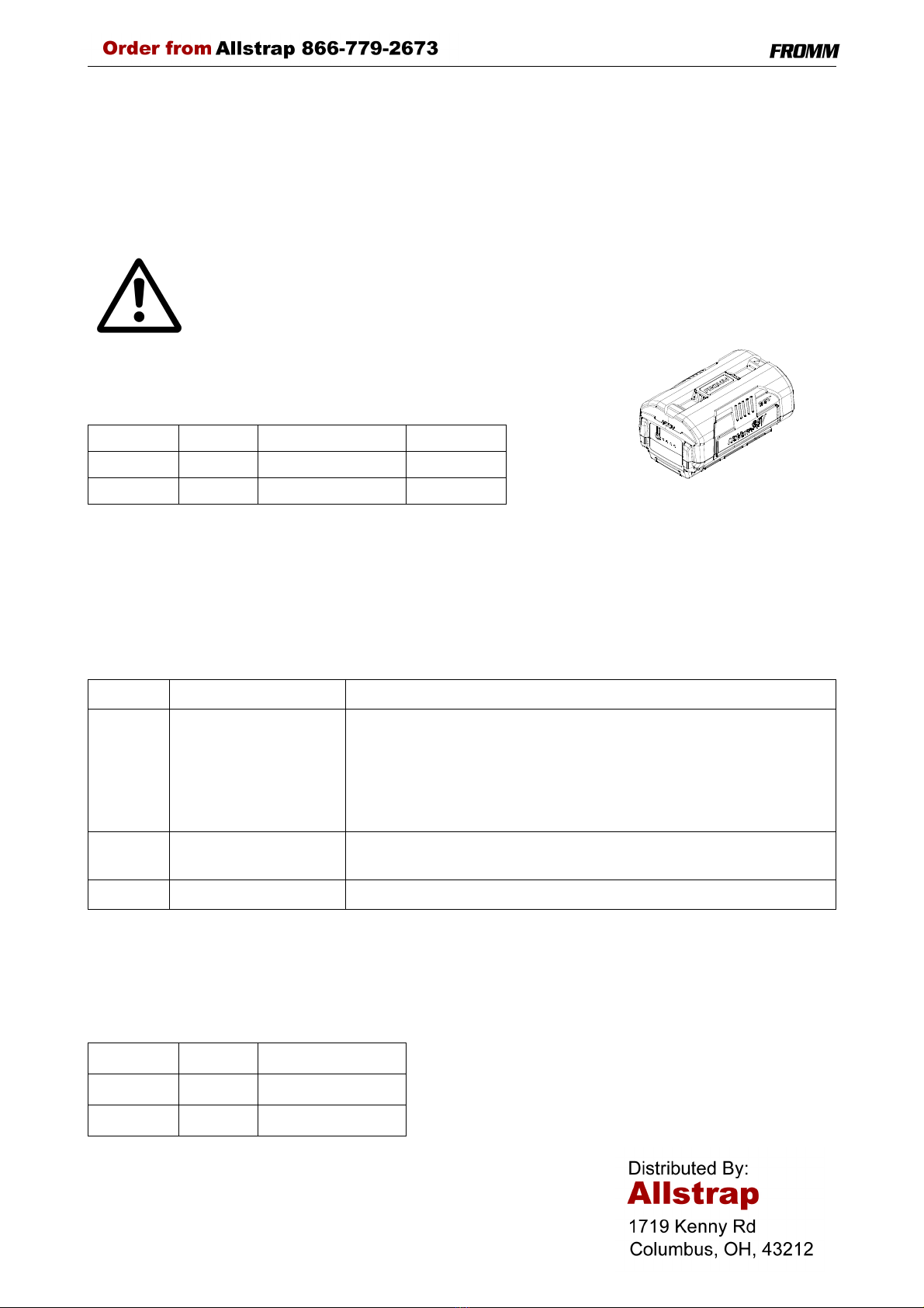
4.1 Battery
The battery is not automatically supplied with the tool. The battery has to
be ordered separately under the following item numbers.
4.2 Battery - chargers
The charger must be ordered separately according to below shown table.
Charging times
Item-No. Battery Voltage Capacity
N5.4337 Li-Ion 36 VDC 2.5 Ah
N5.4341 Li-Ion 36 VDC 4.0 Ah
Item-No. Voltage / frequency Admitted for country
N5.4453 220 - 240V / 50 - 60Hz A, B, BG, BIH, BOL, BR, BY, CH, CL, CZ, D, DK, DZ, E, EAS, EST,
ET, F, FIN, GE, GR, H, HK, HR, I, IL, IND, IR, IRQ, IS, JOR, KSA,
KWT, L, LAR, LT, LV, MA, MC, MK, MOC, N, NL, P, PK, PE, PL, PRC,
PY, RA, RCH, RI, RL, RO, ROK, ROU, RP, RUS, S, SK, SLO, SYR,
THA, TN, TR, UA, UAE, YU, YV, (BRN), (BRU), (CY), (EAK), (EAT),
(GB), (IRL), (M), (MAL), (OM), (SGP), (Y), (Z), (ZA), (ZW)
N5.4455 120V / 50 - 60Hz BR, C, CDN, CO, CR, DOM, EC, GCA, J, JA, KSA, LB, MEX, NIC,
PA, Puerto Rico, RC, RP, USA, YV
N5.4457 220 - 240V / 50 - 60Hz AUS, NZ
Item-No. Battery Charging time
N5.4337 Li-Ion approx. 86 min.
N5.4341 Li-Ion approx. 135 min.

8P331 M_HA mane-12.fm
4.3 Suspension
When working stationary the P331 can be suspended at a spring loaded balancer by using a suspension
bracket. With the swivel mounted suspension bracket the package can be strapped in various working
positions.
The complete suspension bracket can be ordered under item number P33.0216.
4.4 Turning button kit
For a remaining adjustment of tension force and welding time.
After exchanging of the turning buttons the adjustment can only be changed with the allen key (2mm) that
comes with the kit. The kit can be ordered under the item number P32.2061.
P33.0216
N1.5105
N2.5623
P35.2073
P33.2147
P35.2069
N1.2110
Mobilux EP2
P35.2067
P33.2148
N6.6212

9
P331 M_HA mane-12.fm
4.5 Wearing plate
As an option, the tool can be equipped with a wearing
plate to protect the base from excessive wear on
abrasive package surfaces.
The complete wearing plate can be ordered together
with the fastening screws under item number
P33.0214.
4.6 Protection plate (plastic)
For using the P331 on packages with sensitive
surface there can a plastic protection plate be
mounted for protecting the package.
The complete protection plate can be ordered
together with the fastening screws under item
number P33.0215.
5 OPERATING ELEMENTS
P33.0214
N1.2163
P33.2144
P33.2146
P33.0215 N1.2163
Tension button
Sealing button
LED
Handle lever
LED - Indication at the tool
Green During tensioning the LED lights green.
Blue Welding is initiated.
(only in automatic mode)
Green During welding the LED lights green.
Yellow Cooling time is running, the tool must not
be removed from the strap.
Blue
blinking
Motor overheated,
Motor cool down time running.
If during this time a switch is operated, an
acoustic signal happens.
Green +
Acoustic
signal
Cooling time is finished; the tool can be
removed from the strap.
Red Charge the battery.
Red
blinking
Malfunction: e.g. lowering motor blocked.
Remove battery
Clear malfunction
Insert battery
Without
indication
Power saving mode
Unlatching
push button

10 P331 M_HA mane-12.fm
6OPERATION
6.1 Installation
Do not expose power tools to rain or wet conditions!
The batteries are supplied partially charged.
Before the first use, the battery must be completely charged.
See separate operating instruction of the battery charger.
Never charge a damaged battery. Replace by a new one immediately.
Do not open batteries and store them only in dry and frost-proof rooms.
Do not store the battery pack together with metal objects (short circuit risk).
The maximum ambient temperature is 50°C.
Keep dry at all times.
Inserting the battery
• Insert the battery from top to bottom into the tool until the
unlatching push button is engaged.
When inserting the battery the LED - indication shortly lights
green.
Removing the empty battery
If the red LED starts lighting while a tensioning or welding
procedure, the capacity of the battery is exhausted. All
electric functions of the tool are blocked.
The battery must be recharged.
• Push the unlatching push button at the battery.
• Pull the battery out of the tool.
Displaying of the status of the battery charge
By pressing a button the status of the battery can be
shown in four steps.
If four lamps are lighting the battery is full.
If only one lamp is lighting shortly the battery has to be
charged.
Unlatching
push button
Push here

11
P331 M_HA mane-12.fm
6.2 Adjustments
6.2.1 Preselecting of strap tension and tensioning speed
Do not adjust the tensioning force too high.
If the tensioning force is higher than the tensioning strength of the strap,
the strap will tear while the tensioning.
Tensioning force and tensioning speed can be preselected
with the upper adjusting knob.
Turning clockwise increases;
turning counter clockwise decreases the tensioning force
and the tensioning speed resp..
The tensioning force on the minimum setting is 1200 N
(270 lbs) and it is increased on the maximum setting to
7000 N (1575 lbs).
The tensioning speed on the minimum setting is 39 mm/s
(1.5 inch/sec), it is increasing linear up to 63 mm/s
(2.5 inch/sec) on the maximum setting.
6.2.2 Adjusting the welding time
Depending on the size and quality of the strap, different
welding times are required.
The welding time can be adjusted at the lower adjusting
knob.
Turning clockwise increases,
turning counter clockwise decreases the welding time.
6.2.3 Choose operation mode
There are 2 operation modes possible.
1. Manual
In this operation mode is the tensioning as well as the welding of the strap started by the operator.
2. Semi-Automatic
In this operation mode the welding of the strap is automatically started as soon as the preselected tension has
been reached.
The choice of the operation mode can be made with the adjustment screw for operation mode.
Operation mode Manual Operation mode Semi-Automatic
Turn adjustment screw with a screw driver in the desired position.
Adjusting knob tensioning force /
tensioning speed
Adjusting knob
welding time
The adjustment knobs can be
easily turned with a coin.

12 P331 M_HA mane-12.fm
6.3 Feeding the strap around the
package
• The strapping is fed around the package as
illustrated.
Warning! The plastic strap which will be welded
must be free from oil, grease and other dirt.
Dirty plastic straps can't be welded correct!
6.4 Inserting the strap
• Pull up the handle lever firmly with your right
hand.
• Insert the two straps well aligned on each other
into the strap guide using your left hand.
The lower strap end must slightly protrude the
end of the base plate.
• Release the handle lever.
6.5 Tensioning the strap,
Operation mode Manual
• Press down the tension button and then
release it again after the desired strap tension
has been reached.
The tensioning operation can be interrupted and
restarted at any time.
During tensioning the LED lights green.
After automatic cut off of the tensioning force
it can be tensioned again not before
8 seconds.

13
P331 M_HA mane-12.fm
6.6 Sealing the straps,
Operation mode Manual
• Press and release immediately the sealing button.
The plastic strap is welded and cut off from the rest of
the strap.
During the welding the LED lights green.
After elapsing of the adjusted welding time (see
6.2.2) the cooling time begins (LED lights yellow).
During that time the tool must not be removed from
the strap.
6.7 Tensioning and sealing the strap
Operation mode Semi-Automatic
• Push tension button until the adjusted tension
force is reached.
During tensioning the LED lights green.
The tensioning operation can be interrupted and
restarted at any time.
After reaching the adjusted strap tension the sealing
cycle is initiated automatically (LED lights blue).
Welding gripper is lowered,
the welding starts (LED lights green).
• Release the tension button after the sealing
process has been started.
The plastic strap is welded and cut off from the rest of the strap.
After elapsing of the adjusted welding time (see 6.2.2) the cooling time begins (LED lights yellow).
The tool must not be removed from the strap as long as the cooling time is not
finished. Disregard of this regulation is causing insufficient seal efficiencies, which
can cause severe injuries.
6.8 Removing the tool
After the cooling time is elapsed an acoustic signal
happens and the LED lights green again. The sealing
process is finished.
• Pull up the handle lever,
• pull the tool right and off the strapping.

14 P331 M_HA mane-12.fm
6.9 Seal - Control
A regular control of the seal is necessary. The seal can be examined visually.
Make a seal, peel it apart and examine it as follows:
Correct seal
The seal must be completely welded over the whole width of the strap
on a length of ca. 25 mm. Minor quantities of fused plastic may
overflow on sides.
Welding time too short
The plastic strap is not welded over the whole width of the strap. The
seal efficiency is insufficient.
Warning! Straps with insufficient seal strength must be removed from
the package! Adjust the welding time (see 6.2.2).
Welding time too long
If the welding time is too long the straps are overheated. The fused
plastic overflows on both sides of the straps. The seal efficiency is
affected.
Warning! Straps with insufficient seal strength must be removed from
the package! Adjust the welding time (see 6.2.2).
7 CHART OF TYPES P331 M/HA
8 ELECTRIC SCHEMATIC ELS.1084
Item No. Model Strap width Strap thickness
43.0274 P331/19/0.80-1.19/7.0 19.0 mm / 3/4" 0.80 - 1.19 mm / .031" - .046"
43.0276 P331/19/1.20-1.53/7.0 19.0 mm / 3/4" 1.20 - 1.53 mm / .047" - .060"
43.0282 P331/25/0.60-0.79/7.0 25.0 mm / 1" 0.60 - 0.79 mm / .023" - .030"
43.0284 P331/25/0.80-1.19/7.0 25.0 mm / 1" 0.80 - 1.19 mm / .031" - .046"
43.0286 P331/25/1.20-1.35/7.0 25.0 mm / 1" 1.20 - 1.35 mm / .047" - .053"
43.0292 P331/32/0.60-0.79/7.0 32.0 mm / 1 1/4" 0.60 - 0.79 mm / .023" - .030"
43.0294 P331/32/0.80-1.19/7.0 32.0 mm / 1 1/4" 0.80 - 1.19 mm / .031" - .046"
43.0296 P331/32/1.20-1.35/7.0 32.0 mm / 1 1/4" 1.20 - 1.35 mm / .047" - .053"
36VDC
-
blackblack
-
+
red
21
UB
2 1
M3
2
3
1
red
blue
1
2
(-)
(+)
M2
U
V
Wyellow
violett
brown
Hall3
Hall2
Hall1
GND
+5V
5
4
3
2
1
M1
2
1black
red (+)
(-)
HA
M
Manual / 1/2 Auto

15
P331 M_HA mane-12.fm
9 EXCHANGE OF WEARING PARTS
Remove always the battery from the tool before starting maintenance works.
9.1 Exchange of tensioning wheel and grippers
Disassembling
• Unscrew cover P33.2143 and remove it;
• Unscrew end cover P35.0226 and remove it;
• Raise tension wheel by lifting the handle lever P33.2117;
• Remove the tensioning wheel together with the bearing N31.1148 from the tool;
• Unscrew the holder P35.4184 and remove it from the body;
• Remove the grippers from the body.
Assembling in opposite order.
Assembly advise
• Lubricate the internal toothing of the tensioning wheel with Molykote BR2 plus.
• Observe the position of the tensioning wheel. The direction of rotation of the tensioning wheel is marked at
the front of the tensioning wheel (see drawing).
• Observe the position of the grippers (see drawing).
• Safe the screws N1.1305 with Loctite 222.
N31.1148
Tensioning wheel
Grippers
N1.1305
N1.6504
P35.0226
N1.1924
N1.6503
N1.1919
N1.1168
P35.4184
Molykote BR2 plus
Loctite 222
P33.2143
P33.2117
N1.1965
N1.6504
N1.6504

16 P331 M_HA mane-12.fm
9.2 Exchange of cutter, welding stop gripper and welding gripper
Disassembling
• Unscrew motor housing and remove it;
• Unscrew cover P33.2143 and remove it;
• Unscrew end cover P35.0226 and remove it;
• Lift tension gear; pull off tensioning wheel together with bearing N31.1148 from the body.
• Remove cover P35.4213;
•Don’t loosen screw N1.1553 at the coupler P35.0227.
• Disassemble the security ring N2.1121 from the coupler, remove the coupler;
• Pull out the centering sleeve P33.2142 from the guide case, disassemble the guide case;
• Remove the cutter P35.4198 together with the pressure spring and the guide from the driving pin P35.4110;
• Take pressure spring N21.5211 together with the spring guide P35.4199 from the cutter.
• Disassemble strap guide plate P35.4105;
• Disassemble the screws N1.1305, lift slightly the welding stop gripper P35.4104 and the steel insert and remove
them from the tool;
• Push the steel insert without welding stop gripper under the welding gripper P35.4107 until it touches the parallel
pin N2.2110;
• Turn welding gripper down, in case the welding gripper does not sit on the steel insert, put a piece of plastic
strap underneath the steel insert;
• Disassemble the safety ring N2.1118 from the bolt P35.4210, remove the bolt from the welding gripper;
• Turn welding gripper up;
• Pull out the steel insert with care to right under the welding gripper;
• Lift the rocker P35.4106 behind the welding gripper with a screw driver, remove the welding gripper together with
the ball cage P32.1027 and the balls N3.1702 from the tool;
• Lower the rocker, remove the thrust piece P32.1029 from the tool.
Assembling in opposite order.
P33.2142
N21.5211
N1.1932
N1.6505
P35.0227
6 x N3.1702
N1.1305
N1.6504
P35.4105
P35.4213
P35.4104
N2.2118
Molykote BR2 plus
Loctite 222
Klüber Isoflex Alltime SL2
Klüber Isoflex NBU 15
Mobilux EP2
P31.1124
N2.1121
P35.4199
P35.0226
P33.2143
N11.1116
P35.4210
N1.6504
P35.4107
P32.1029
P32.1027
P35.4106
N1.6504
N1.1927
N1.1966
N1.1934
N1.1553
Motor housing
P35.4198
Guide case
Steel insert
Tensioning wheel

17
P331 M_HA mane-12.fm
Assembly advise
• During assembling move the strap guide plate P35.4105 downwards against the holding gripper.
• Before mounting the motor housing check the proper seat of the tube P31.1124, it must be pushed in
completely (see drawing).
• Pay attention to the fitting position of the cutter (see drawing).
• Safe the screws N1.1305 with Loctite 222.
• Lubricate the rocker and the bolt P35.4210 in the area of the welding gripper with Klüber Isoflex NBU 15.
• Lubricate the balls, ball cage and the running surface of the balls on the welding gripper with Klüber Isoflex
Alltime SL2.
• Lubricate the cutter and the driver with Mobilux EP2.
9.3 Adjustment of the coupler
The coupler is adjusted in our works.
In case of replacing the seesaw lever, the coupler or the lever body, the coupler has to be readjusted.
Procedure as follows:
The battery is removed from the tool.
The coupler is fitted into the tool.
• Loosen screw N1.1553.
• Displace thrust piece, so that it touches the two
seesaw levers without moving them.
• Re-tighten screw N1.1553.
Control:
The thrust piece must touch the seesaw levers (X1).
Both guide pins must sit on the welding stop
gripper (X2).
10 CLEANING
Clean strap gripping parts from strap abrasion
regularly using compressed air.
Thus also the cover can be removed and with a
suitable air gun air been blown on the welding
elements.
Do not use any mechanical tool for cleaning.
When cleaning the surface of the tool do not use water
or aggressive solvents!
11 SERVICE
Servicing and repair work must only be carried out by authorized service centres.
If the tool breaks down or does no longer operate do not disassemble it. Send it fully assembled to the local
service centre (see name and address on the rear page of this manual). Use original packing.
In order to prevent damages to the motor shaft the two needle free wheeling N3.4509 have to be replaced
after maximum 80 000 strapping cycles.
The battery powered plastic strapping tool P331 is a high performance tool. We strongly recommend you to
have it serviced by an authorized service shop after 12 months at the latest if used one shift per day. If used
two or more shifts per day the tool has to be serviced after a shorter period of time.
N1.1553
X1
X2
Coupler
Thrust piece
Seesaw lever
Guide pin
Welding stop
gripper

18 P331 M_HA mane-12.fm
12 TRANSPORT
Lithium-ion batteries are subject to the Dangerous Goods Legislation requirements. The user can transport
the batteries by road without further requirements.
When being transported by third parties (e.g.: air transport or forwarding agency), special requirements on
packaging and labelling must be observed.
For preparation of the item being shipped, consulting an expert for hazardous material is required.
Dispatch batteries only when the housing is undamaged.
Tape or mask off open contacts and pack up the battery in such a manner that it cannot move around in the
packaging.
Please also observe possibly more detailed national regulations.
13 DISPOSAL
The machine, rechargeable batteries, accessories and packaging
should be sorted for environmental- friendly recycling.
Do not dispose of power tools and batteries/rechargeable batteries into
household waste!
Only for EC countries:
According to the European Guideline 2002/96/EC, power tools that are
no longer usable, and according to the European Guideline 2006/66/EC,
defective or used battery packs/batteries, must be collected separately
and disposed of in an environmentally correct manner.
14 WARRANTY CONDITIONS AND LIABILITY
FROMM Holding AG warrants all its strapping tools and machine heads during a period of 12 months from the
date sale.
The warranty includes all deficiencies clearly resulting from poor manufacturing or faulty materials. Damage
claims as a result of production shutdowns and claims for damage to persons and to property resulting from
warranty deficiencies cannot be asserted by the customer.
The warranty excludes:
• wearing parts (tensioning wheels, cutters, punches, dies, notching knifes, grippers, batteries and
motors),
• deficiencies resulting from improper installing, incorrect handling and maintaining the tool,
• deficiencies resulting from using the tool without or with defective security- and safety devices,
• disregard of directions in the operation manual,
• arbitrary modifications of the tool,
• deficient control of wearing parts,
• deficient repair works of the tool,
• use of consumable products not recommended by FROMM Holding AG.
We reserve the right to modify the product at any time in order to improve its quality.
15 APPROPRIATE USE
The tool model P331 has been designed to strap packages with plastic strapping exclusively.
For the use in hazardous areas the tool is not suitable.
The warranty / liability excludes:
• non appropriate use of the tool,
• disregard of directions in the operation manual,
• disregard of control- and maintenance instructions.

19
43028601.z
A1
B
C
23456
D
3N21.2106
2P35.4196
N31.1148
2N3.2111
N31.1148
N1.6503
N2.2119
P33.2149
P35.4184
P35.4186
P35.4187
P35.4185
N1.1305
N1.6504
N1.2222
P35.4193
N1.6504
N11.1116
P35.4105
N43.9181
N1.6504
N2.4902
N4.9159
P33.2143
N1.1919
N1.1924
N1.1965
N1.6504
2P33.2229
P35.0226
3N2.2147
N1.1168
N3.1174
N3.3103
P35.4197
N1.6504
P33.0208
P33.0212
1 Mobilux EP2
2 Molykote BR 2 plus
3 Loctite 603
4 Loctite 222
5 Klüber Isoflex Alltime SL2
6 Klüber Isoflex NBU 15
7 1 Nm
8 Orientation
9 NyoGel 760G

20 43028601.z
A7
B
C
8 9 10 11 12
D
N2.4902
N43.9182
N1.1932
N1.6505
1P33.2106
1N21.5216
1P33.2105
1N2.5157
N2.2443
4N1.1305
N1.6504
5P32.1029
P33.2130
N2.1121
5P35.4107
6P35.4210
N2.5178
P33.2142
P35.4204
N2.2162
P32.1251
N2.1121
N1.6504
P35.4205
P35.4203
1P35.4111
1P35.4111
P35.4213
N1.6505
N1.1932
P35.4104 P33.1236
P33.1237
P33.2132
N2.2162
N1.1553
P35.4202
P33.0203
5N3.1702
5P32.1027
P33.0201
N3.3189
N31.3111
P33.2102
P35.4103
P35.0227
N2.1118
N2.2110
N2.2187
1 Mobilux EP2
2 Molykote BR 2 plus
3 Loctite 603
4 Loctite 222
5 Klüber Isoflex Alltime SL2
6 Klüber Isoflex NBU 15
7 1 Nm
8 Orientation
P33.0212
P35.4110
N21.5211
1P35.4198
P35.4199
This manual suits for next models
1
Table of contents
Other Fromm Packaging Equipment manuals

Fromm
Fromm P355.0001.01 User manual

Fromm
Fromm FS13 Series User manual

Fromm
Fromm FS33 Series User manual

Fromm
Fromm P329 M User manual

Fromm
Fromm A334 Guide

Fromm
Fromm AP210 Instructions for use

Fromm
Fromm A332 User manual

Fromm
Fromm P328S User manual

Fromm
Fromm FS15 Series User manual

Fromm
Fromm FSW10 User manual