PERIODIC MAINTENANCE AND CONTROL
1-9
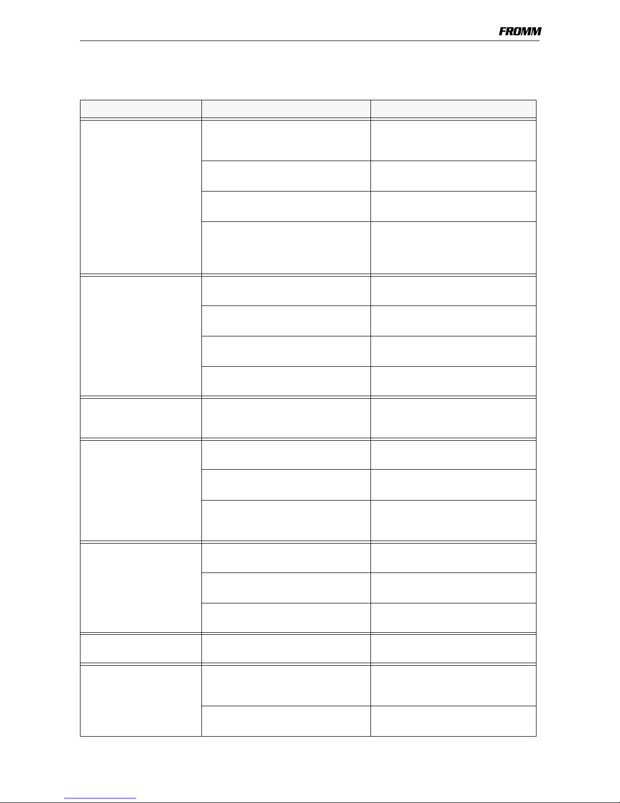
1.3.2 Troubleshooting
A sufficient compressed air supply and the use of the tool’s specific strap should be guaranteed before
each tool repair.
SYMPTOM CAUSE REMEDY
Tool doesn’t tension,
Tensioning motor runs
The tensioning wheel is packed with
strap residue or is worn and mills on
the strap
Clean tensioning wheel with
compressed air or replace it
Wrong tensioning wheel or tensioning
wheel is assembled reversed
Correct assembling or use the correct
tensioning wheel.
Grippers are dirty, worn or wrongly
assembled
Replace grippers, clean them with
compressed air or assemble correctly
Gearing parts from the tensioning gear
are defective
Loose pinion P32.1123 on tensioning
motor
Check tensioning gear and replace
defect parts
Tensioning motor doesn’t
run
Tensioning motor defective Check component parts and replace
damaged ones
Tensioning gear defective Check component parts and replace
damaged ones
Pneumatic control system is defective Check component parts and replace
damaged ones
Needle free wheeling assembled
reversed
Assemble correctly
Tensioning wheel turns
back immediately after the
tensioning cycle
Defective needle free wheeling
N3.4509
Check and replace if necessary
Tool doesn’t weld,
welding motor runs
Welding gripper is dirty or worn Clean and check welding gripper and
replace damaged one
Welding stop gripper is dirty or worn Clean and check welding stop gripper
and replace damaged one
Pinion P32.1023 lose at the motor or
welding eccentric, resp. The journal at
the welding eccentric is broken off.
Check component parts and replace
damaged ones
Welding motor doesn’t run Welding motor defective Check component parts and replace
damaged ones
Welding mechanism defective Check component parts and replace
damaged ones
Pneumatic control system is defective Check component parts and replace
damaged ones
Gear noise Tensioning or welding gear is worn Check component parts and replace
damaged ones
Welding motor does not
stop
Turn off valve or welding motor valve
jam, resp. the welding time valve is
blocked.
Check and clean parts, exchange
damaged parts
Diameter of the air supply hose is too
small.
Install air supply hose with a minimum
inner diameter of 9mm (3/8")