ACCESSORY TOOLS
1-17
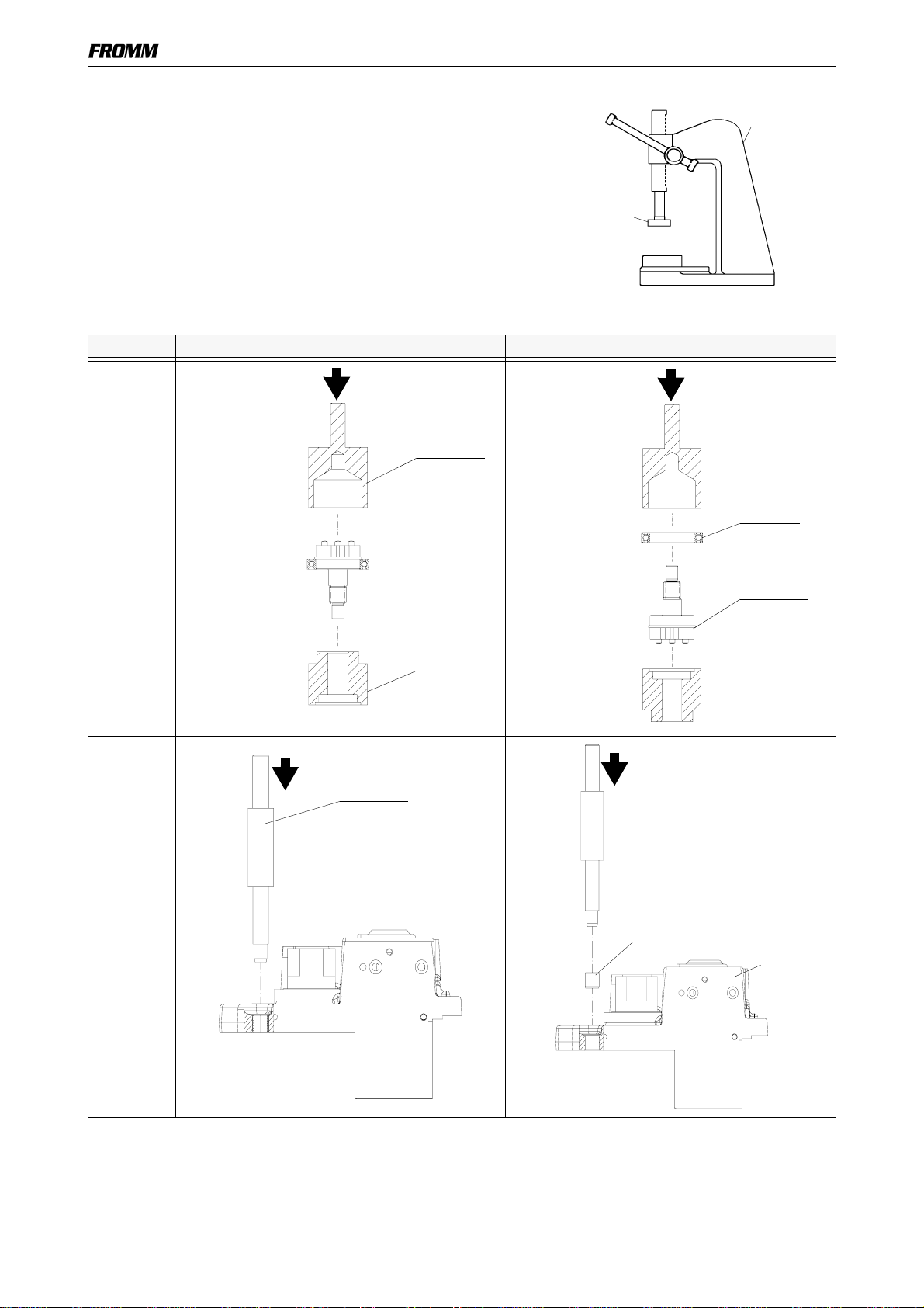
1.5 ACCESSORY TOOLS
* a) These tools are also included in the P320 tool set.
b) These tools are also included in the P321 tool set.
c) These tools are also included in the P350 tool set.
d) These tools are also included in the P355 tool set.
Item
number Field Use
N71.3235 *a,d F5 Press in and press out arbor for N3.4509/P35.3118
N71.3238 *a,d F3 Press in and press out pressure pad for N3.1159/P32.1037
N71.3239 *a,d F7 Press in arbor for N3.2347/P32.1510
N71.3240 *a,d F7 Press out arbor for N3.2347/P32.1510
N71.3241 *a,d F7 Press in and press out pressure pad for N3.2347/P32.1510
N71.3266 *b F8 Press out arbor for N3.2356/P35.3211
N71.3237 *a,b,d F3, F8 Press in and press out arbor for N3.1159/P32.1037
and for N3.2356/P35.3211
N71.3243 *a,d F6 Press in arbor for N3.1134, P32.1023/P35.3123
N71.3244 *a,d F6, F9 Press out arbor for N3.1134, P32.1023/P35.3123; P35.0140/P32.1023
N71.3245 *a,d F6, F8 Pressure pad for N3.1134, P32.1023/P35.3123; N3.2356/P35.3211
N71.3264 *a F1 Press in and press out arbor for N3.1157/P35.3103
N71.3247 *a,d F1 Press in and press out pressure pad for N3.1157/P35.3103
N71.3248 *a,d F4 Press in arbor for N3.3150/P35.3204 or P35.3205
N71.3268 *a F4 Press out pressure pad for N3.3150/P35.3204 or P35.3205
N71.3250 *a,d F2 Press in and press out arbor for N3.3172/P35.3101
N71.3254 *a,d F9 Press on arbor for P32.1023/P35.0140
N71.3267 *b F4 Press in arbor for N3.3150/P35.3204 or P35.3205
N71.3278 F5 Press in and press out pressure pad for N3.4509/P35.3118
N71.3274 *d F11,F12,
F13 Hook for exhaust ring P35.2005, P35.3129/P35.3101;
P35.2059 and P35.3142/P35.3141
N71.3281 *d F9 Press on pressure pad for P32.1023/P35.0140
N71.3276*dF10 Pressure pad for P35.3138 resp. P35.3106/P35.2023, N3.1174
N71.3277*dF10 Thrust piecefor P35.3138resp. P35.3106/P35.2023, N3.1174
N71.3280 *d F9 Press out pressure pad for P32.1023/P35.0140
N71.3214 *c F14 Hook for throttle seat P35.2057/P35.3141
-- -- For the slotted round nut N1.5602 take a commercially face spanner