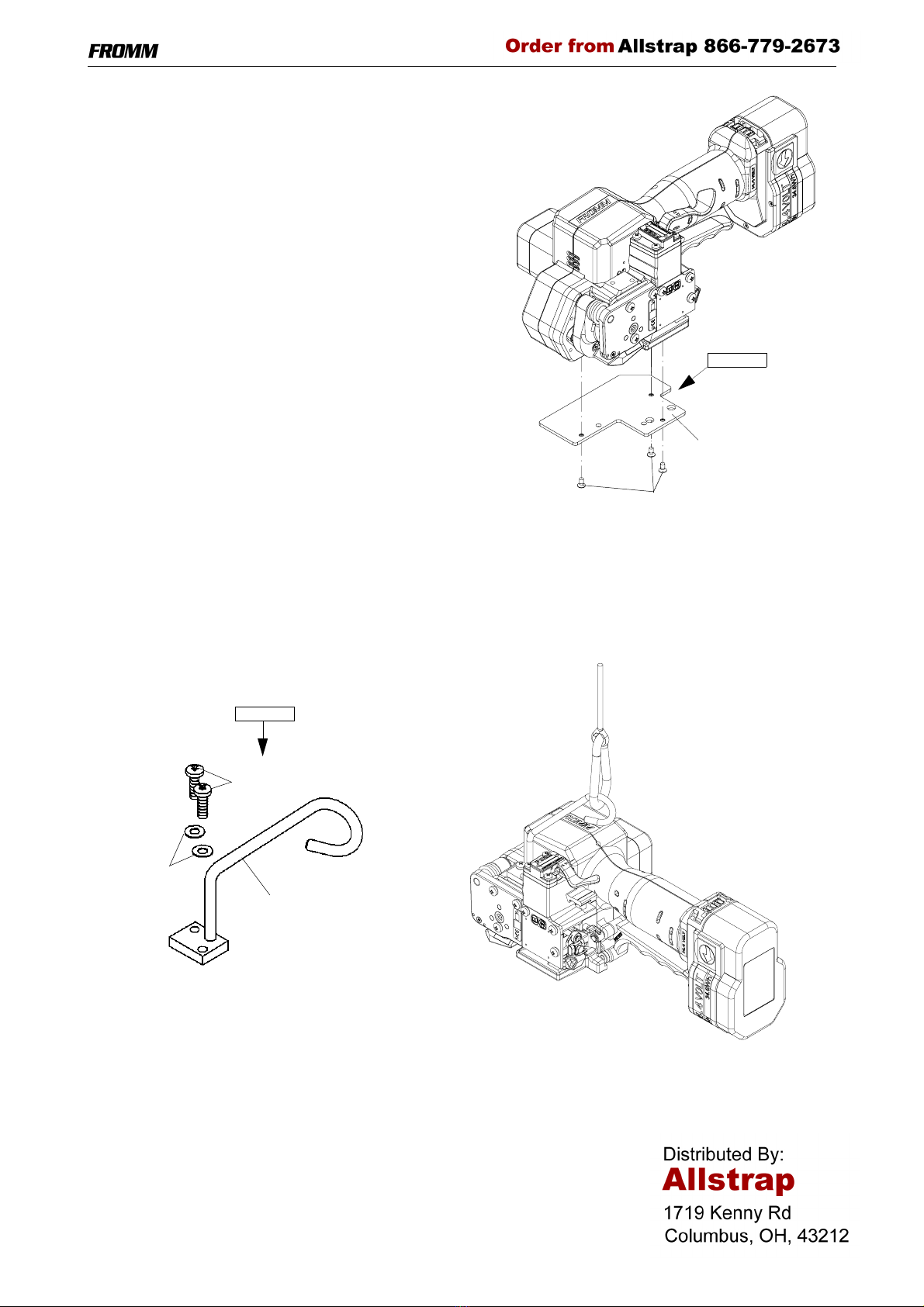
Fromm P322 Guide

43212401.en/MAS/© 08.05
CE Declaration of conformity
We declare that the machine P322
is in conformity with the following standard or
standardised documents:
98/37/EEC
FROMM Holding AG
Hinterbergstrasse 26
CH - 6330 Cham
12.08 2005
R.Fromm
Director
OPERATION MANUAL / SPARE PARTS LIST
BATTERY - POWERED
PLASTIC STRAPPING TOOL
MODEL P322
43.2124.01

2
INDEX PAGE
1 SAFETY INSTRUCTIONS 3
2 TECHNICAL DATA 4
3 ACCESSORIES 5
3.1 Battery . . . . . . . . . . . . . . . . . . . . . . . . . . . . . . . . . . . . . . . . . . . . . . . . . . . . . . . . 5
3.2 Battery - chargers . . . . . . . . . . . . . . . . . . . . . . . . . . . . . . . . . . . . . . . . . . . . . . . 5
3.3 Wearing plate . . . . . . . . . . . . . . . . . . . . . . . . . . . . . . . . . . . . . . . . . . . . . . . . . . 6
3.4 Suspension . . . . . . . . . . . . . . . . . . . . . . . . . . . . . . . . . . . . . . . . . . . . . . . . . . . . 6
3.5 Turning button kit. . . . . . . . . . . . . . . . . . . . . . . . . . . . . . . . . . . . . . . . . . . . . . . . 7
4 OPERATING ELEMENTS 8
5 OPERATION 8
5.1 Installation . . . . . . . . . . . . . . . . . . . . . . . . . . . . . . . . . . . . . . . . . . . . . . . . . . . . . 8
5.2 Adjustments. . . . . . . . . . . . . . . . . . . . . . . . . . . . . . . . . . . . . . . . . . . . . . . . . . . . 9
5.2.1 Preselecting of strap tension and tensioning speed . . . . . . . . . . . . . . . . . . . . . 9
5.2.2 Adjusting the welding time. . . . . . . . . . . . . . . . . . . . . . . . . . . . . . . . . . . . . . . . . 9
5.3 Feeding the strap around the package . . . . . . . . . . . . . . . . . . . . . . . . . . . . . . . 9
5.4 Inserting the strap . . . . . . . . . . . . . . . . . . . . . . . . . . . . . . . . . . . . . . . . . . . . . . 10
5.5 Tensioning the strap . . . . . . . . . . . . . . . . . . . . . . . . . . . . . . . . . . . . . . . . . . . . 10
5.6 Sealing of the joint . . . . . . . . . . . . . . . . . . . . . . . . . . . . . . . . . . . . . . . . . . . . . 11
5.7 Removing the tool . . . . . . . . . . . . . . . . . . . . . . . . . . . . . . . . . . . . . . . . . . . . . . 11
5.8 Seal - Control. . . . . . . . . . . . . . . . . . . . . . . . . . . . . . . . . . . . . . . . . . . . . . . . . . 11
6 CHART OF TYPES 12
7 ELECTRIC SCHEMATIC 12
8 EXCHANGE OF WEARING PARTS 13
8.1 Exchange of tensioning wheel and grippers . . . . . . . . . . . . . . . . . . . . . . . . . . 13
8.2 Exchange of cutter, welding stop gripper and welding gripper . . . . . . . . . . . . 14
8.3 Adjustment of the coupler P32.1250 . . . . . . . . . . . . . . . . . . . . . . . . . . . . . . . . 15
9 WARRANTY CONDITIONS AND LIABILITY 16
10 APPROPRIATE USE 16
11 SERVICE 16
12 CLEANING 16
13 SPARE PARTS LIST 43.2124.01 21

3
P322mane.fm
1 SAFETY INSTRUCTIONS
Read these instructions carefully. Failure to follow these instructions can result in severe personal injury.
Operation with battery
Environment protection:
• Do not dispose of used batteries in the household refuse,
water or by burning them.
FROMM distributors offer an environment friendly battery
disposal service.
Danger of shortcircuit:
• Do not store batteries together with metal objects.
• Do not open batteries and store them only in dry and frost-
proof rooms. The maximum ambient temperature is 50°C.
Keep dry at all times.
• Never charge a damaged battery. Replace by a new one
immediately.
Eye injury hazard
Failure to wear safety glasses with side shields can result in
severe eye injury or blindness. Always wear safety glasses with
side shields which conform to ANSI Standard Z87.1.
Operation
Tool must not be used by persons not properly trained in their use.
Before tensioning strap, read and understand the tool operating
instructions. Failure to follow the operating instructions or improper
load positioning could result in strap breakage.
Become familiar with your tool and keep fingers away from areas
that can pinch or cut.
Joints
You are fully responsible to review the joints made by your tool.
Become familiar with the seal control and seal adjustment
described in this operation manual. Misformed joints may not
secure the load and could cause serious injury. Never handle or
ship any load with improperly formed joints.
Dispensing strap
Only dispense strap from a dispenser specifically designed for
strap.
Tuck strap end back into dispenser when not in use.
Strap warnings
Never use strap as a means of pulling or lifting loads. Failure to
follow these warnings can result in severe personal injury.
Strap breakage hazard
Improper operation of the tool, excessive tensioning, using strap
not recommended for this tool or sharp corners on the load can
result in a sudden loss of strap tension or in strap breakage during
tensioning, which could result in the following:
• A sudden loss of balance causing you to fall.
• Both tool and strap flying violently towards your face.
Note as follows:
• If the load corners are sharp, use edge protectors.
• Place the strap correctly around a properly positioned
load.
• Positioning yourself in-line with the strap, during
tensioning and sealing, can result in severe personal
injury from flying strap or tool. When tensioning or sealing,
position yourself to one side of the strap and keep all
bystanders away.
• Use the correct strap quality, strap width, strap gauge and
strap tensile strength recommended in this manual for
your tool. Using strap not recommended for this tool can
result in strap breakage during tensioning.
Cutting tensioned strap
When cutting strapping, use the proper strapping cutter and keep
other personnel and yourself at a safe distance from the strap.
Always stand to side of the strap, away from the direction the
loosened strap end will fly. Use only cutters designed for strap and
never hammers, pliers, hacksaws, axes, etc.
Fall hazard
Keep your working area tidy. Untidiness of your working area may
cause a risk of injury. Maintaining improper footing and/or balance
when operating the tool can cause you to fall. Before tensioning
and especially in elevated areas, always establish good balance.
Both feet should be securely placed on a flat, solid surface,
especially when working in elevated areas. Do not use the tool
when you are in an awkward position.
Pay attention to the rules and regulations for preventions of
accident which are valid for the work place.
Tool hazards
A well maintained tool is a safe tool!
Check tool regularly for broken or worn parts. Do not operate a
tool with broken or worn parts.
Never modify any tool. Modification can result in severe bodily
injury.

4P322mane.fm
2 TECHNICAL DATA
Description of the tool
The tool model P322 has been designed to strap packages with plastic strapping. The plastic strapping is fed
around the package manually or in combination with a strap feeder. The straps are inserted in the tool,
automatically tensioned, sealed by friction welding and separated.
Tool size with battery
Length: 335 mm / 13.2"
Width: 159 mm / 6.3“
Height: 126 mm / 5.0"
Weight: 4.4 kg / 9.7 lbs
Sound information
The A-weighted equivalent continuous sound level at the work place of the machine operator is
typical 81 dB (A).
This value was determined according to DIN 45 635 T3 (11.85).
Vibration information
The weighted effective value of the acceleration typically amounts to less than 2,5m/s2.
This value was determined according to DIN EN 28 662 T1 (01.93).
Strap material
Strap qualities: PET (Polyester) and PP (Polypropylene) plain or embossed.
Use only plastic straps recommended by your sales shop (name and address
on the rear of the operation manual).
Strap dimensions: 10.0 - 16.0 mm / 3/8 - 5/8“ x 0.4 - 1.05 mm / .016 - .041“ (see chart of types).
Use only plastic straps with the correct strap dimensions for your tool.
Strap tension
Tensioning force: Adjustable from 400 - max. 2000 N / 90 - max. 450 lbs.
The maximum value depends on the strap quality.
Tensioning speed: 250 - 340 mm/s / 9.8 - 13.4"/sec.
Joint strength: approx. 75% of the tensile strength of the plastic strap
(depending on the strap quality).
Working temperature
The ambient temperature should be between 5° and 45° C (41° and 113°F).
The best performance is achieved between 15° and 20°C (59° and 68°F).

5
P322mane.fm
3 ACCESSORIES
Use only parts and accessories mentioned in the operating instruction. Using other
parts or accessories can cause injuries to you and other persons.
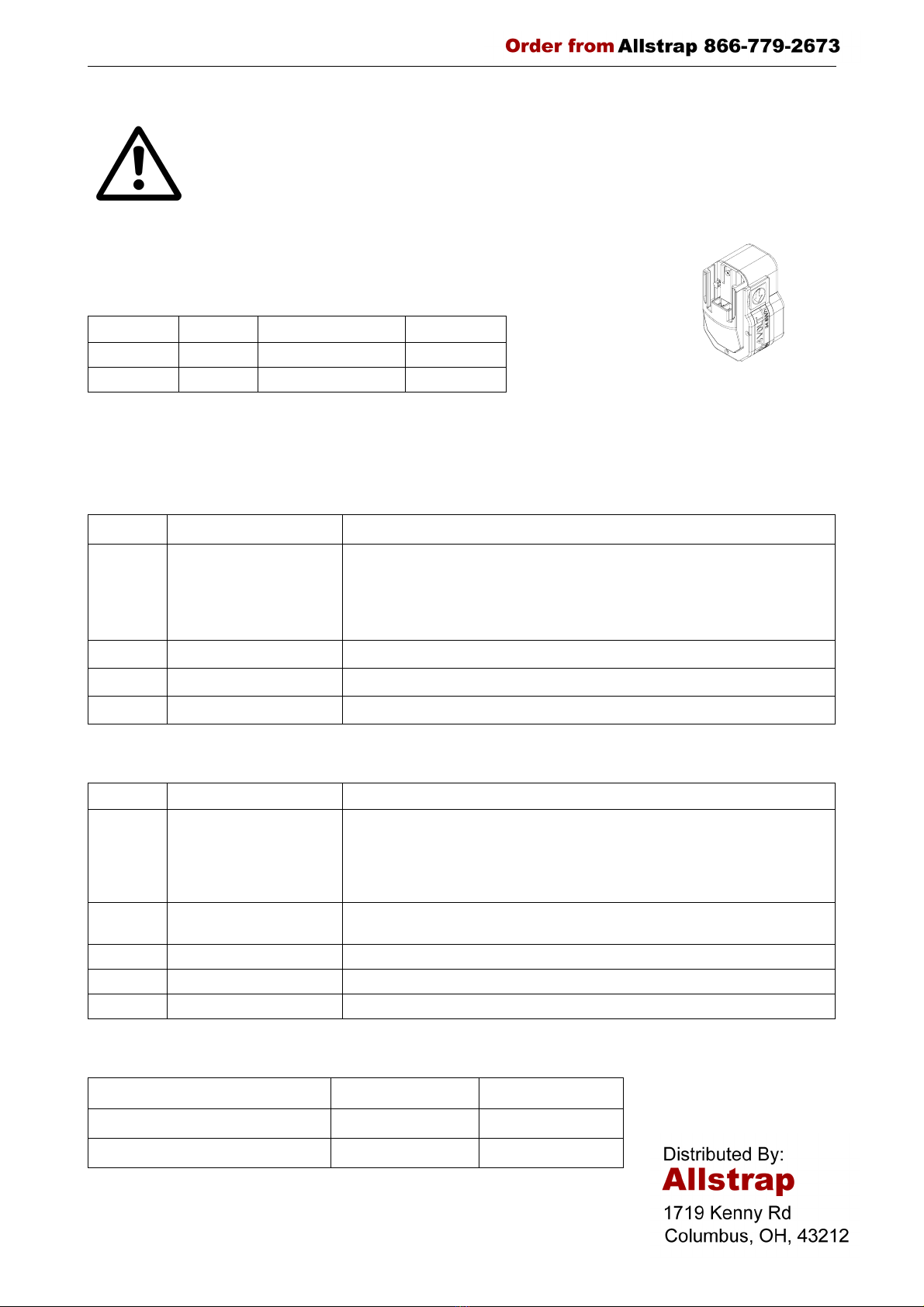
3.1 Battery
Since the tool can be operated with NiCd or NiMH batteries, the battery is not
automatically supplied with the tool. The battery has to be ordered separately under
the following item numbers.
3.2 Battery - chargers
The charge must be ordered separately according to below shown table.
Standard charger
Turbo charger
Charging times
Item-No. Battery Voltage Capacity
N5.4309 NiCd 14,4 VDC 2,4Ah
N5.4316 NiMH 14,4 VDC 2,7Ah
Item-No. Voltage / frequency Admitted for country
N5.4414 220 - 240V / 50 - 60Hz A, B, BG, BIH, BOL, BR, BY, CH, CL, CZ, D, DK, DZ, E, EAS, EST, ET, F,
FIN, GE, GR, H, HK, HR, I, IL, IND, IR, IRQ, IS, JOR, KSA, KWT, L, LAR, LT,
LV, MA, MC, MK, MOC, N, NL, P, PK, PE, PL, PRC, PY, RA, RCH, RI, RL,
RO, ROK, ROU, RP, RUS, S, SK, SLO, SYR, THA, TN, TR, UA, UAE, YU,
YV, (Z), (ZA), (ZW)
N5.4416 220 - 240V / 50 - 60Hz BRN, BRU, CY, EAK, EAT, GB, IRL, M, MAL, OM, SGP, Y
N5.4418 220 - 240V / 50 - 60Hz AUS, NZ
N5.4420 220V / 60Hz ROK
Item-No. Voltage / frequency Admitted for country
N5.4422 220 - 240V / 50 - 60Hz A, B, BG, BIH, BOL, BR, BY, CH, CL, CZ, D, DK, DZ, E, EAS, EST, ET, F,
FIN, GE, GR, H, HK, HR, I, IL, IND, IR, IRQ, IS, JOR, KSA, KWT, L, LAR, LT,
LV, MA, MC, MK, MOC, N, NL, P, PK, PE, PL, PRC, PY, RA, RCH, RI, RL,
RO, ROK, ROU, RP, RUS, S, SK, SLO, SYR, THA, TN, TR, UA, UAE, YU,
YV, (Z), (ZA), (ZW)
N5.4424 120V / 60Hz BR, C, CDN, CO, CR, DOM, EC, GCA, J, JA, KSA, LB, MEX, NIC, PA,
Puerto Rico, RC, RP, USA, YV
N5.4426 110V / 50 - 60Hz GB
N5.4428 220 - 240V / 50 - 60Hz BRN, BRU, CY, EAK, EAT, GB, IRL, M, MAL, OM, SGP, Y
N5.4430 220 - 240V / 50 - 60Hz AUS, NZ
Standard charger Turbo charger
NiCd-Battery 14,4 VDC, 2,4Ah approx. 80 min. approx. 20 min.
NiMH-Battery 14,4 VDC, 2,7Ah approx. 85 min. approx. 25 min.

6P322mane.fm
3.3 Wearing plate
As an option, tool can be equipped with a wearing plate to
protect base from excessive wear on abrasive package
surfaces (like bricks, concrete blocks etc.).
The complete wearing plate can be ordered together with
the fastening screws under item number P32.0111.
3.4 Suspension
When working stationary the P322 can be suspended at a spring loaded balancer by using a suspension
bracket.
For working in normal position a stiff suspension bracket with screws and washers can be ordered under item
number P32.0112.
P32.0111
N1.2221
P32.1301
P32.0112
N1.6503
N1.1912
P32.1303

7
P322mane.fm
For working in alternating positions a turn able suspension bracket with screws and washers can be ordered
under item number P32.0137.
3.5 Turning button kit
For a remaining adjustment of tension force and welding time.
After exchanging of the turning buttons the adjustment can only be changed with the allen key (2mm) that
comes with the kit. The kit can be ordered under the item number P32.1129.
P32.0137
N1.5105
N2.5623 ➂
P35.2073 ➂
P32.1310
P35.2069 ➂
➂ P32.1307
N1.1904
N1.6503
➂ ESSO Beacon 2

8P322mane.fm
4 OPERATING ELEMENTS
5 OPERATION
5.1 Installation
Do not expose the tool to rain!
For safety reasons the battery is delivered uncharged.
Charge the battery before working. See separate operating instruction of the battery charger.
Inserting the battery
Insert the battery from bottom to top into the tool
both unlatching push buttons latch.
Depending on the application, the battery can also
be inserted from top to bottom in order achieve a
better handling.
When inserting the battery the status of the charge
is displayed shortly.
Displaying of the status of the battery
charge by LED
Green blinking full
Green yellow
blinking
3/4 full
Yellow blinking 1/2 full
Yellow - red blinking 1/4 full
Red blinking empty
LED - Indication
Green During tensioning the LED
lights green.
Green During welding the LED lights
green.
Yellow Cooling time is running, the
tool must not be removed from
the strap.
Green Cooling time is finished, the
tool can be removed from the
strap.
Red Charge the battery.
Red blinking The control board is
overheated,
the tool has to cool down,
the switches are locked.
Lever LED
Switch rocker
Unlatching
Handle lever
push button

9
P322mane.fm
Removing the empty battery
If the red LED starts lighting while a tensioning or welding procedure, the capacity of the battery is exhausted.
All electric functions of the tool are blocked.
The seal efficiency is insufficient.
Warning! Straps with insufficient seal strength must be removed from the package!
The battery must be recharged.
Push the unlatching push buttons at both sides of the battery.
Push the battery out of the tool in the opposite direction of insertion.
When removing the battery the LED lights shortly red.
5.2 Adjustments
5.2.1 Preselecting of strap tension and tensioning speed
Do not adjust the tensioning force too high.
If the tensioning force is higher than the tensioning strength of the strap,
the strap will tear while the tensioning.
Tensioning force and tensioning speed can be
preselected with the right adjusting knob.
Turning clockwise increases;
turning counterclockwise decreases the tensioning
force and the tensioning speed resp.
The tensioning force on the minimum setting is
400 N (90 lbs) and it is increased on the maximum
setting to 2000 N (450 lbs).
The tensioning speed on the minimum setting is
250 mm/s (9.8 inch/sec), it is increased on the
middle setting to 340 mm/s (13.4 inch/sec) and
remains on this value till the maximum setting.
5.2.2 Adjusting the welding time
Depending on the size and quality of the strap,
different welding times are required.
The welding time can be adjusted at the left
adjusting knob.
Turning clockwise increases,
turning counterclockwise decreases the welding
time.
5.3 Feeding the strap around the
package
The strapping is fed around the package as
illustrated.
Warning! The plastic strap which will be
welded must be free from oil, grease and
other dirt.
Dirty plastic straps can't be welded
correct!
Adjusting knob welding time
Adjusting knob tensioning force /
tensioning speed

10 P322mane.fm
5.4 Inserting the strap
Pull up the handle lever firmly with your right
hand.
Insert the two straps well aligned on each other
into the strap guide using your left hand.
Release the handle lever.
5.5 Tensioning the strap
Press down the switch rocker and then release it
again after the desired strap tension has been
reached.
The tensioning operation can be interrupted and
restarted at any time.
During tensioning the LED lights green.
Do not press the switch rocker after reaching
the preselected tensioning.
Danger of strap breakage.
The tool must carry out a balance movement while tensioning.
Therefore:
- Don’t hinder the tools movement in the signed direction.
Disregard:
- The feed wheel slips on the strap without tensioning it.

11
P322mane.fm
5.6 Sealing of the joint
Press sealing lever down and let it go immediately.
The plastic strap is welded and cut off from the rest
of the strap.
During the welding the LED lights green.
After elapsing of the adjusted welding time (see
5.2.2) the cooling time begins (LED lights yellow).
During that time the tool must not be removed from
the strap.
If the LED lights green again, the sealing cycle is
finished.
The tool must not be removed from the strap as long as the cooling time is not
finished. Disregard of this regulation is causing insufficient seal efficiencies, which
can cause severe injuries.
5.7 Removing the tool
Pull up the handle lever,
pull the tool right / backwards and off the strapping.
5.8 Seal - Control
A regular control of the seal is necessary. The seal can be examined visually.
Make a seal, peel it apart and examine it as follows:
Correct seal
The seal must be completely welded over the whole width of the strap
on a length of ca. 19 mm. Minor quantities of fused plastic may
overflow on sides.
Welding time too short
The plastic strap is not welded over the whole width of the strap. The
seal efficiency is insufficient.
Warning! Straps with insufficient seal strength must be removed from
the package! Adjust the welding time (see 5.2.2).
Welding time too long
If the welding time is too long the straps are overheated. The fused
plastic overflows on both sides of the straps. The seal efficiency is
affected. Warning! Straps with insufficient seal strength must be
removed from the package! Adjust the welding time (see 5.2.2).

12 P322mane.fm
6 CHART OF TYPES
7 ELECTRIC SCHEMATIC
Item No. Model Strap width Strap thickness
43.2101 P322/10/0.40-0.64 10 mm / 3/8" 0.4 - 0.64 mm / .016 - .025"
43.2102 P322/10/0.65-1.05 10 mm / 3/8" 0.65 - 1.05 mm / .026 - .041"
43.2111 P322/11.1/0.40-0.64 11.1 mm / 7/16" 0.4 - 0.64 mm / .016 - .025"
43.2112 P322/11.1/0.65-1.05 11.1 mm / 7/16" 0.65 - 1.05 mm / .026 - .041"
43.2121 P322/12/0.40-0.64 12 mm 0.4 - 0.64 mm / .016 - .025"
43.2122 P322/12/0.65-1.05 12 mm 0.65 - 1.05 mm / .026 - .041"
43.2123 P322/12.7/0.40-0.64 12.7 mm / 1/2" 0.4 - 0.64 mm / .016 - .025"
43.2124 P322/12.7/0.65-1.05 12.7 mm / 1/2" 0.65 - 1.05 mm / .026 - .041"
43.2131 P322/13/0.40-0.64 13 mm 0.4 - 0.64 mm / .016 - .025"
43.2132 P322/13/0.65-1.05 13 mm 0.65 - 1.05 mm / .026 - .041"
43.2151 P322/15/0.40-0.64 15 mm 0.4 - 0.64 mm / .016 - .025"
43.2152 P322/15/0.65-1.05 15 mm 0.65 - 1.05 mm / .026 - .041"
43.2153 P322/15.5/0.40-0.64 15.5 mm 0.4 - 0.64 mm / .016 - .025"
43.2154 P322/15.5/0.65-1.05 15.5 mm 0.65 - 1.05 mm / .026 - .041"
43.2161 P322/16/0.40-0.64 16 mm / 5/8" 0.4 - 0.64 mm / .016 - .025"
43.2162 P322/16/0.65-1.05 16 mm / 5/8" 0.65 - 1.05 mm / .026 - .041"

13
P322mane.fm
8 EXCHANGE OF WEARING PARTS
Remove always the battery from the tool before starting maintenance works.
8.1 Exchange of tensioning wheel and grippers
Disassembling
• Unscrew end cover P32.1238 and remove it;
• Remove the torsion spring N2.5823;
• Remove the tensioning body P32.1254;
• Remove the tensioning wheel together with the bearing N3.1172 from the tool;
• Unscrew the holders P32.1228 and P32.1229 and remove them from the tensioning body;
• Remove the grippers from the tensioning body.
Assembling
Assembling in opposite order. Observe the following:
• Lubricate the internal toothing of the tensioning wheel with Molykote BR 2 plus.
Observe the position of the tensioning wheel. The direction of rotation of the
tensioning wheel is marked at the front of the tensioning wheel (see drawing).
Observe the position of the grippers (see drawing).
N3.1172
Tensioning wheel ➃
Grippers
N2.5823
N1.1909
N1.6505
P32.1238
N1.1904
N1.6503
P32.1229
P32.1228
P32.1254
➃ Molycote BR2 plus

14 P322mane.fm
8.2 Exchange of cutter, welding stop gripper and welding gripper
Disassembling
• Unscrew cover P32.1211 and remove it;
• Unscrew end cover P32.1238 and remove it;
• Remove security ring N2.1118 and pull handle shaft P32.1415 out of the tool.
This is loosening the lever P32.1414;
• Tilt down the handle lever P32.1212 and remove it from the tool;
• Don’t loosen screw N1.1553 at the coupler P32.1250.
• Disassemble the security ring N2.1121 from the coupler P32.1250, remove the coupler;
• Pull out the centering sleeve P32.1208 from the guide case to left, disassemble the guide case;
• Pull out the pressure spring N2.5237 with a screw driver from the cutter P32.1204;
• Remove the cutter from the driving pin P32.1032;
• Disassemble the screws N1.1305, lift slightly the welding stop gripper P32.1203 and the steel insert and
remove them from the tool;
• Push the steel insert without welding stop gripper under the welding gripper P32.1053 until it touches the
parallel pin N2.2110;
• Press down lever P32.1406;
• Disassemble the safety ring N2.1121 from the bolt P32.1028, remove the bolt from the welding gripper;
• Press in coupler P32.1410 in order to release the lever P32.1406 again;
• Pull out the steel insert with care to right under the welding gripper;
• Disassemble the security rings N2.1121 from the driving pin P32.1032, remove the driver P32.1035 from
the driving pin;
• Lift the rocker P32.1024 behind the welding gripper with a screw driver, remove the welding gripper
together with the ball cage P32.1027 and the balls N3.1702 from the tool;
• Lower the rocker, remove the thrust piece P32.1029 from the tool.
P32.1212
P32.1415
N2.1121
P32.1035 ➂
N2.1121
P32.1035 ➂
N1.1904
N1.1929
N1.6503
P32.1211
P32.1208
Guide case
P32.1250
N2.1121
➂ P32.1204
N2.5237
P32.1028 ➅
P32.1027 ➄
6 x N3.1702 ➄
Steel insert
P32.1203
➁ N1.1305
N1.6504 P32.1053 ➄
P32.1238
N1.1904
N1.6503
N2.1118
P32.1414 ➂
P32.1032
P32.1410
P32.1406
➁ Loctite 222
➂ ESSO Beacon 2
➄ Klüber Isoflex Alltime SL2
➅ Klüber Isoflex NBU 15
P32.1029 ➄

15
P322mane.fm
Assembling
Assembling in opposite order. Observe the following:
Pay attention to the fitting position of the cutter (see drawing).
Safe the screws N1.1305 with Loctite 222.
Lubrication
• Lubricate the rocker and the bolt P32.1028 in the area of the welding jaw with Klüber Isoflex NBU 15.
• Lubricate the balls, ball cage and the running surface of the balls on the welding gripper with Klüber Isoflex
Alltime SL2.
• Lubricate the cutter and the driver with Esso Beacon 2.
8.3 Adjustment of the coupler P32.1250
The coupler is adjusted in our works.
In case of replacing the seesaw lever, the coupler or the lever body, the coupler has to be readjusted.
Procedure as follows:
The battery is removed from the tool.
The coupler is fitted into the tool.
• Loosen screw N1.1553.
• Displace thrust piece P32.1252, so that it touches
the two seesaw levers without moving them.
• Retighten screw N1.1553.
Control:
The thrust piece must touch the seesaw levers (X1).
Both guide pins must sit on the welding stop
gripper(X2).
Coupler
Thrust piece
N1.1553
Seesaw lever
Welding stop
X1
X2
Guide pin
gripper

16 P322mane.fm
9 WARRANTY CONDITIONS AND LIABILITY
FROMM Holding AG warrants all its strapping tools and machine heads during a period of 90 days from the
date of sale. The warranty includes all deficiencies clearly resulting from poor manufacturing or faulty materials.
Damage claims as a result of production shutdowns and claims for damage to persons and to property resulting
from warranty deficiencies cannot be asserted by the customer.
The warranty excludes:
wearing parts,
deficiencies resulting from improper installing, incorrect handling and maintaining the tool,
deficiencies resulting from using the tool without or with defective security- and safety devices,
disregard of directions in the operation manual,
arbitrary modifications of the tool,
deficient control of wearing parts,
deficient repair works of the tool.
Use of consumable products not recommended by FROMM Holding AG
We reserve the right to modify the product at any time in order to improve its quality.
10 APPROPRIATE USE
The tool model P322 has been designed to strap packages with plastic strapping exclusively.
The warranty / liability excludes:
• non appropriate use of the tool,
• disregard of directions in the operation manual,
• disregard of control- and maintenance instructions.
11 SERVICE
Servicing and repair work must only be carried out by authorized service centres.
If the tool breaks down or does no longer operate do not disassemble it. Send it fully assembled to the local
service centre (see name and address on the rear page of this manual). Use original packing.
The battery powered plastic strapping tool P322 is a high performance tool. We strongly recommend you to
have it serviced by an authorized service shop after 12 months at the latest if used one shift per day. If used
two or more shifts per day the tool has to be serviced after a shorter period of time.
12 CLEANING
Clean strap gripping parts from strap abrasion regularly using compressed air (do not use any mechanical tool
for cleaning).
When cleaning the surface of the tool do not use water or aggressive solvents!

17
43212401.z
A1
B
C
D
23456
➀ Loctite 603
➁ Loctite 222
➂ ESSO Beacon 2
➃ Molycote BR2 plus
➄ Klüber Isoflex Alltime SL2
➅ Klüber Isoflex NBU 15
P32.1402
P32.1401
N2.2110
P32.1050 ➂
➀N2.2188
N2.2188 ➀
N3.1172
➃N3.2106
N3.1172
N2.2187
P32.1217 ➃
P32.1218 ➃
P32.1220 ➃
P32.1229
P32.1228
P32.1225
P32.1226
P32.1227
N3.2346
P32.1238
N4.9159
N2.4902
N1.6503
N1.1904
N3.3172
P32.1233
N1.2216
N2.5823
➀N2.2189
N1.6505
N1.1909
P32.0136
P32.1216 ➂
N2.3342
N3.3172
P32.1003 ➀
P32.1242
N2.2187
N1.2223
P32.0110
P32.1254
P32.0138

18 43212401.z
A7
B
C
D
8 9 10 11 12
➀ Loctite 603
➁ Loctite 222
➂ ESSO Beacon 2
➃ Molycote BR2 plus
➄ Klüber Isoflex Alltime SL2
➅ Klüber Isoflex NBU 15
N4.1803 ➂
➂N4.1803
N43.9108
N2.4902
P32.1406
N1.1925
N1.6504
P32.1407
P32.0142
P32.1416
P32.1404 ➂
P32.1405 ➂
N3.3174
N3.3174
N2.2443
P32.0139
N2.5294 ➂
P32.1403 ➂
N2.5295 ➂
N2.5157 ➂
P32.1402
N2.5296 ➂
P32.1410 ➂P32.1249
N2.2193
P32.1206
P32.1251
N2.1121
P32.1252
N1.6504
N1.1553
P32.1029 ➄
➄P32.1027
➄N3.1702(6x)
N1.6504
➁N1.1305
N2.1121
➂P32.1035
P32.1053 ➄
➂P32.1035
N2.1121
N2.5237
➂P32.1204
P32.1032
P32.1028 ➅
N2.5178
P30.1157
P30.1163
P32.1248
P32.1210
P32.1210
P32.1208
P32.1211
N41.9127
N1.6503
N1.1904
N1.1904
N1.1929
P32.1250
➅P32.1012
P32.1011
P32.1203
P32.1202
P32.0138

19
43212401.z
A13
B
C
D
14 15 16 17 18
P32.1049 ➃
N3.1160
P32.0119
P32.0120
P32.1048 ➃
N3.1178
N2.1610
N1.2112 ➁
P32.1047
P32.1046 ➃
N3.2105 ➃
P32.0118
N2.2145 ➀
➃P32.1044
➀ Loctite 603
➁ Loctite 222
➂ ESSO Beacon 2
➃ Molycote BR2 plus
➄ Klüber Isoflex Alltime SL2
➅ Klüber Isoflex NBU 15
N3.1157
N2.2122
N2.2122
N2.2119
P32.1411 ➂
P32.0140
P32.1412
N2.5235 ➂
P32.1018
P32.1408 ➂
P32.1417
P32.1409
N1.6505
N1.1948
P32.1015
P32.1016 ➃
N3.4509
P32.1014
P32.1051 ➅
P32.1052
N2.1801
N2.5822
P32.0138
P32.1402

20 43212401.z
A19
B
C
D
20 21 22 23 24
P32.1123 ➃
N5.1129
P32.0108
P32.1122
P32.1121
N6.6271
N1.1934 N1.7207
N1.1934
N1.6504
N5.2702
N2.1606
N1.7208
N4.9108
N41.9160 P32.1419
P32.1108
P32.1111
P32.1114
P32.0106
P32.1118
P32.1107
P32.0107
P32.1126
P32.1122
N5.1129
N6.6271
P32.1121
P32.1120
N3.1158
P32.1119 ➃
N1.6331 ➃
P32.1037 ➃
N3.1159➀
➀ Loctite 603
➁ Loctite 222
➂ ESSO Beacon 2
➃ Molycote BR2 plus
➄ Klüber Isoflex Alltime SL2
➅ Klüber Isoflex NBU 15
N1.6331 ➃
N2.2190
P32.1212
P32.1418
N41.9160
N2.1118
P32.1414➂
P32.1415
P32.1011
N1.7207
P32.1421
P32.1124
(N3.3174)
(P32.1106)
(P32.1105)
(N1.7206)
(N1.7206)
(N5.2322)
(N5.2322)
P32.1413
P32.1023 ➃
N3.1134
P32.1022
P32.1024 ➅
N3.2347
N3.1134
P32.0144
P32.1021
P32.0138
P32.1402
This manual suits for next models
1
Table of contents
Other Fromm Packaging Equipment manuals

Fromm
Fromm AP210 User manual

Fromm
Fromm FS130 Series User manual

Fromm
Fromm P328S User manual

Fromm
Fromm P328 M User manual

Fromm
Fromm P380 User manual

Fromm
Fromm P355.0001.01 User manual

Fromm
Fromm FS33 Series User manual

Fromm
Fromm A383.0003 Guide

Fromm
Fromm A383.0001 Guide

Fromm
Fromm AP210 Instructions for use