manuals.online logo
Brands
  1. Home
  2. •
  3. Brands
  4. •
  5. FV
  6. •
  7. Toilet
  8. •
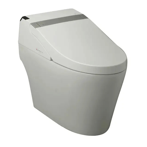
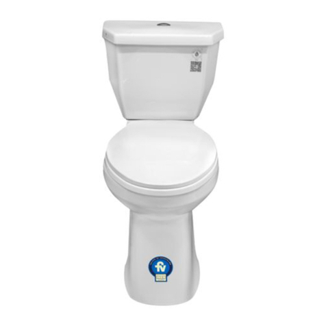
  9. FV Greco Touchless 4.8 L User manual

FV Greco Touchless 4.8 L User manual

FV se reserva el derecho de modificar,
cambiar, mejorar y/o anular materiales,
productos y/o diseños sin previo aviso.
MEDIDAS SUGERIDAS PARA LA INSTALACIÓN (en cm):
Código:
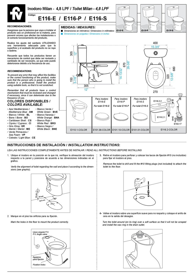
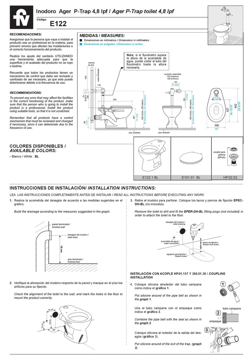
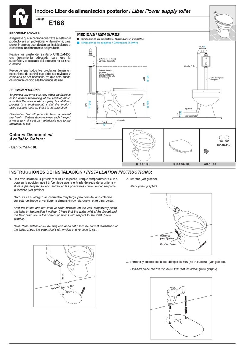
Asegúrese que la persona que vaya a instalar el
producto sea un profesional en la materia, para
prevenir errores que afecten las instalaciones o
el correcto funcionamiento del producto.
Realice los ajuste del sanitario UTILIZANDO
una herramienta adecuada para que la
superficie y el acabado del producto no se raye
o lastime.
Recuerde que todos los productos tienen un
mecanismo de control que debe ser revisado y
cambiado de ser necesario, ya que este puede
deteriorarse debido a la frecuencia de uso.
To prevent any error that may affect the facilities
or the correct functioning of the product, make
sure that the person who is going to install the
p
roduct is a professional. Install the product
using suitable tools, so that it is not scratched.
Remember that all products have a control
mechanism that must be reviewed and changed
if necessary, since it can deteriorate due to the
frequency of use.
RECOMENDACIONES:
RECOMMENDATIONS:
MEDIDAS / MEASURES:
Dimensiones en milímetros / Dimensions in millimeters
Dimensiones en pulgadas / Dimensions in inches
796
31-3/8”
305
446
17-9/16”
150
5” 7/8
328
12-15/16”
Ø 65
22,8
1-1/8”
2-9/16”
2-9/16”
2-9/16”
746
29-3/8”
472
18-9/16”
429
16-15/16”
363
143
143
143
5-3/8”
E165.1-COLOR E101.25-COLORECAP-DH E174.2-COLOR
E164.2.2-COLOR
HM.30
E174.2.1-COLOR
LEA LAS INSTRUCCIONES COMPLETAMENTE ANTES DE INSTALAR / READ ALL INSTRUCTIONS BEFORE INSTALLING
INSTRUCCIONES DE INSTALACIÓN / INSTALLATION INSTRUCTIONS
1.
Ubique el inodoro en su lugar de destino. Verifique la alineación del inodoro
respecto a la pared; sitúelo de acuerdo a las dimensiones sugeridas y marque
en el piso los orificios para su fijación.
Verify the alignment of toilet regarding the wall and place it according to the dimen-
sions (see graphic). For drilling mark on the floor the hole’s position.
90º
15 cm
30.5 cm
15 cm
acometida
de agua /
water supply
2.
Retire el inodoro, perfore y coloque los tacos de fijación # 10. Limpie el área de
trabajo y verifique que el interior del desagüe en el piso esté libre de objetos
(papel, trapos, etc.) que puedan obstaculizar la descarga normal.
Drill and place the fixation bolts #10 (not included) (view graphic). Clean the work
area and check inside the drain to make sure it is free of objects that may be an
obstacle for water discharge.
4.
Nuevamente coloque el inodoro en su sitio. Verifique que se inserte correcta-
mente el extremo plástico del anillo de cera en el desagüe del piso. Nivele el
inodoro y fíjelo al piso con los pernos de sujeción. Selle la unión entre el ino-
doro y el piso con un cordón de silicona.
Once more locate the toilet in it’s place. Verify the correct insertion of plastic end of
wax ring in the floor drain. Align and secure the toilet to the floor with bolts. Seal the
joint between the toilet and the floor with a bead of silicon adhesive.
3.
Voltee el inodoro sobre una superficie suave para no rasparlo y coloque el
anillo de cera en la salida del desagüe.
Turn the toilet around (on its ring) over a soft surface so that it will not be scraped
and install the wax ring in the drain outlet.
anillo de cera
wax ring
COLORES DISPONIBLES /
COLORS AVAILABLE:
• Blanco / White : BL
• Bone / Bone : BO
E174
Inodoro Greco Touchless 4,8 L. / Toilet Greco Touchless 4.8 L.
Fecha: 2021 - 01 - 11
soporte
sensor
50.5 mm
(A)
(B)
tapa sensor sensor
adhesivo
utiliza 3
baterías
AAA
FUNCIONAMIENTO MANUALFUNCIONAMIENTO
POR SENSOR
destornillador
botón
empaque
tuerca
tuerca
arandela
empaque
neplo
manguera
de entrada
manguera
de entrada
seguro
soporte
botón
arandela
Inserte la manguera
de relleno en el tubo
de desbordamiento
Nivel de agua
6.
Instale el herraje en el tanque.
Utilice una llave angular FV con manguera flexible
(ref.: E266.02 DH CR)
para conectar la válvula de ingreso a la acometida de agua
en la pared.
Install the tank fitting in the toilet. Use a FV angle valve with flexible hose
(ref.:
E266.02 DH CR)
to connect the entry valve to the water supply on the wall.
llave angular FV
con manguera flexible /
FV angle stop
with flexible hose
INSTALACIÓN DEL HERRAJE TOUCHLESS / INSTALLING THE TOUCHLESS HARDWARE:
5.
Instale el herraje en el tanque. Por debajo del tanque inserte el empaque espu-
moso en la salida de la válvula de descarga. Ubique el tanque sobre el inodoro,
alineando las dos piezas. Sujételas con los pernos de anclaje.
Install the fitting in the tank. Under the tank, insert the foamy gasket in the bottom
of the discharge valve. Place the tank on the toilet, aligning the two pieces. Fasten
with anchor bolts.
1. Para instalar la válvula de salida/entrada. Retire
la tuerca y coloque la válvula en el tanque, en la
posición que indica el gráfico #1 y ajuste la
tuerca a la válvula por debajo del tanque.
To install the inlet / outlet valve. Remove the nut
and place the valve in the tank, in the position
indicated by graphic # 1 and tighten the nut to
the valve below the tank.
FUNCIONAMIENTO / FUNCTIONING:
INSTALACIÓN DE LA MANGUERA DE RELLENO /
INSTALLING THE FILLER HOSE
4. Puede instalar el Sensor usando tornillos (A) o Adhiriéndolo a la pared (B).
(A) Para instalar el sensor con tornillos. Coloque temporalmente el soporte del
sensor en el lugar a instalar y marque el lugar donde se realizarán las perforacio-
nes. Realice las perforaciones, coloque los tacos e instale el soporte a la pared.
(B) Para adherir el sensor a la pared, retire el papel del adhesivo del soporte y
coloque en la pared, en el lugar deseado.
Coloque las baterías en la tapa del sensor y ajuste al soporte.
You can install the sensor using screws (A) or Attaching it to the wall (B).
(A) To install the sensor with screws. Temporarily place the sensor bracket in the
place to be installed and mark the place where the holes will be made. Drill the
holes, place the dowels and install the bracket to the wall.
(B) To adhere the sensor to the wall, remove the paper from the adhesive and place
it on the wall, in the desired place.
Place the batteries in the sensor cap and fasten to the sensor holder.
CALIBRACIÓN DEL HERRAJE / HARDWARE CALIBRATION
Válvula de salida/entrada: Para calibrar la válvula de salida/entrada, presione el
botón indicado y baje o suba la válvula según la necesidad (gráfico #6). Para una
calibración más fina, usando un destornillador, ajuste o afloje el tornillo hasta que
el nivel del agua quede en la señal indicada en el tanque (gráfico #7).
Outlet Valve: To calibrate the outlet valve, press the indicated button and lower or
raise the valve as needed (grafic #6). For a finer calibration, using a screwdriver,
adjust or loosen the screw as needed (grafic #7).
2. Ajuste un extremo de la manguera de entrada a la válvula de salida y el otro extre-
mo al neplo que debe estar instalado en la base del tanque (gráfico #2).
Coloque el botón de accionamiento manual al tanque y ajuste colocando el empa-
que, la arandela y la tuerca (gráfico #3). Retire el seguro del soporte del botón y
presione a la parte posterior del botón y vuelva a colocar el seguro (gráfico #4).
Connect one end of the inlet hose to the outlet valve and the other end to the neplo
that must be installed at the base of the tank (graphic # 2).
Attach the actuation button to the tank and tighten by fitting the gasket, washer, and
nut (graphic # 3). Remove the latch from the button holder and push the back of the
button and replace the latch (graphic # 4).
234
67
tuerca
1
perno de anclaje /
anchor bolt empaque espumoso
foamy gasket
tuerca /
nut
Nota: el exceso de ajuste de la tuerca B
puede causar la ruptura de la válvula de
ingreso A.
Note: Over tightening of nut B may cause
rupture of inlet valve A.
A
B
Nota: No es recomendable usar cemento mortero en la base del inodoro. La
Garantía FV no cubre inodoros instalados con mortero.
Antes de instalar el tanque verifique que la tubería de alimentación este limpia y libre
de impurezas y residuos de construcción.
Note: It is not advisable to use cement in the base of the toilet. The warranty doesn't
cover toilets installed with cement.
To fix it Before installing the tank, verify that the feeding pipe is clean and free of sludge
and construction residuals.
soporte
módulo
de control
módulo
de control
módulo
de control
utiliza 4
baterías
AA
3. Cuelgue el soporte del módulo de control a la manguera de entrada y coloque el
módulo (gráfico #5). Conecte los cables como indica el gráfico.
Hang the control module bracket to the inlet hose and attach the module (graphic #
5). Connect the cables as shown in the graphic.
5
This manual suits for next models

1

Other FV Toilet manuals

FV E470 User manual

FV

FV E470 User manual

FV E158-E User manual

FV

FV E158-E User manual

FV E113 User manual

FV

FV E113 User manual

FV E149 User manual

FV

FV E149 User manual

FV Bellini E184 User manual

FV

FV Bellini E184 User manual

FV E183 User manual

FV

FV E183 User manual

FV Apolo E182 User manual

FV

FV Apolo E182 User manual

FV Ginebra E152 User manual

FV

FV Ginebra E152 User manual

FV New Greco 4.8 LPF User manual

FV

FV New Greco 4.8 LPF User manual

FV Ginebra E149 User manual

FV

FV Ginebra E149 User manual

FV Ischia Plus User manual

FV

FV Ischia Plus User manual

FV E149 User manual

FV

FV E149 User manual

FV Trento E176 User manual

FV

FV Trento E176 User manual

FV Ginebra E152 User manual

FV

FV Ginebra E152 User manual

FV E112-E User manual

FV

FV E112-E User manual

FV E158-E User manual

FV

FV E158-E User manual

FV A115-S User manual

FV

FV A115-S User manual

FV E192 User manual

FV

FV E192 User manual

FV Liber E168 User manual

FV

FV Liber E168 User manual

FV Victoria E170 User manual

FV

FV Victoria E170 User manual

FV Catania E194 User manual

FV

FV Catania E194 User manual

FV Parma E157 User manual

FV

FV Parma E157 User manual

FV PARMA E157 User manual

FV

FV PARMA E157 User manual

FV Milan E116-E User manual

FV

FV Milan E116-E User manual

Popular Toilet manuals by other brands

Laufen Pro N rimless H828966 installation instructions

Laufen

Laufen Pro N rimless H828966 installation instructions

Meissen Keramik GENERA instruction manual

Meissen Keramik

Meissen Keramik GENERA instruction manual

Toto CT447CFG01 installation manual

Toto

Toto CT447CFG01 installation manual

Scarabeo Moai 8606 manual

Scarabeo

Scarabeo Moai 8606 manual

American Standard Cadet PRO 215AA Series INSTALLATION INSTRUCTIONS CARE AND MAINTENANCE

American Standard

American Standard Cadet PRO 215AA Series INSTALLATION INSTRUCTIONS CARE AND MAINTENANCE

nella DRAVA NBKD-30A installation instructions

nella

nella DRAVA NBKD-30A installation instructions

Kohler C3-150 Homeowner's guide

Kohler

Kohler C3-150 Homeowner's guide

Helvex WC MIURA 16 TCC installation guide

Helvex

Helvex WC MIURA 16 TCC installation guide

Kohler K-18154 installation guide

Kohler

Kohler K-18154 installation guide

Cinderella CLASSIC product manual

Cinderella

Cinderella CLASSIC product manual

Kallista P70080-00 installation guide

Kallista

Kallista P70080-00 installation guide

Uspa UB-7035R Operating instructions manual

Uspa

Uspa UB-7035R Operating instructions manual

Kohler K-29918T-NSHC installation instructions

Kohler

Kohler K-29918T-NSHC installation instructions

Lipper Sanitation owner's manual

Lipper

Lipper Sanitation owner's manual

Tecma Nano ECO Owners and installation manual

Tecma

Tecma Nano ECO Owners and installation manual

Kohler K-4734-NY Installation and care guide

Kohler

Kohler K-4734-NY Installation and care guide

Glacier bay N2428R-DF TBD manual

Glacier bay

Glacier bay N2428R-DF TBD manual

DURAVIT DuraStyle Dry Replacement manual

DURAVIT

DURAVIT DuraStyle Dry Replacement manual

manuals.online logo
manuals.online logoBrands
  • About & Mission
  • Contact us
  • Privacy Policy
  • Terms and Conditions

Copyright 2025 Manuals.Online. All Rights Reserved.