Gima OXY 110 User manual

M34341-M-Rev.2.02.20
PULSOXIMETRO OXY 110
OXY 110 PULSE OXIMETER
PULSIOXÍMETRO OXY 110
OXYMÈTRE DE POULS OXY 110
PROFESSIONAL MEDICAL PRODUCTS
Gima S.p.A.
Via Marconi, 1 - 20060 Gessate (MI) Italy
gima@gimaitaly.com - export@gimaitaly.com
www.gimaitaly.com
Manuale d’uso - User manual
Manuel de l’utilisateur - Guía de uso
ATTENZIONE: Gli operatori devono leggere
e capire completamente questo manuale
prima di utilizzare il prodotto.
ATTENTION: The operators must carefully read
and completely understand the present manual
before using the product.
AVIS: Les opérateurs doivent lire et bien
comprendre ce manuel avant d’utiliser le produit.
ATENCIÓN: Los operadores tienen que leer y entender
completamente este manual antes de utilizar el producto.
Shenzhen Creative Industry Co., Ltd.
Floor 5, BLD 9, BaiWangxin High-Tech Industrial Park,
Songbai Road, Xili Street, Nanshan District,
518110 Shenzhen, P.R. China
Made in China
0123
Shanghai International
Holding Corp. GmbH (Europe)
Eiffestrasse 80, 20537, Hamburg, Germany
34341 / SP-20

39
Table of Contents
1 Overview......................................................................................................40
1.1 Appearance ............................................................................................ 40
1.2 Product Name and Model ......................................................................42
1.3 Structure .................................................................................................42
1.4 Features..................................................................................................42
1.5 Intended Use ..........................................................................................42
1.6 Working Environment.............................................................................. 42
2 Power Supply ..............................................................................................43
3 Make Measurement....................................................................................45
3.1
SpO2
Measurement ......................................................................................45
3.2 Temperature Measurement (optional) ....................................................46
4 Operation..................................................................................................... 47
4.1 Power on/off the Oximeter......................................................................47
4.2 Default Display Screen ...........................................................................48
4.3 Menu....................................................................................................... 49
4.4 Record ...................................................................................................58
5 Technical Specications ............................................................................ 61
6 Over-limit Indication ................................................................................... 63
6.1 Limit settings ..........................................................................................63
6.2
Over-limit indication sound mute setting ....................................................... 63
7 Packing List.................................................................................................63
8 Repair and Maintenance ............................................................................ 64
8.1 Maintenance ...........................................................................................64
8.2 Cleaning and Disinfecting Instruction..................................................... 64
9 Troubleshooting .......................................................................................... 65
10 Frequently Asked Questions...................................................................... 66
Appendix ..........................................................................................................67
I. Key of Symbols..........................................................................................67
II. Common Knowledge ................................................................................69
ENGLISH

40
1 Overview
1.1 Appearance
Alert
indicator
Figure 1.1 Front view
Figure 1.3 Bottom side view
Figure 1.2 Upper-side view
Record/Back
Right /Sound
Setting/Down
Display screen
Menu/Conrm
Auto-rotate /Up
Power indicator
Power/Left
SpO2:
SpO2probe
connector
USB connector
DC power input
contact shoes
with polarity
indication
TEMP:
Temperature
probe
connector
ENGLISH

41
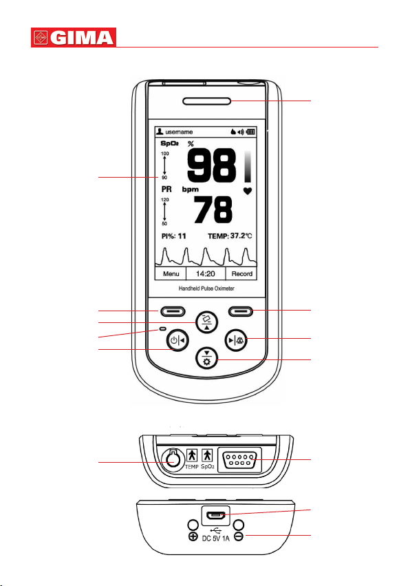
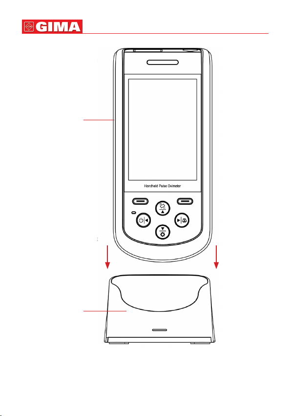
1. Display screen: Display measurement result, trends and menus.
2. (Power/Left): Power on/off the device by longtime pressing; On menu or
sub-menu screen, short time press it to move the cursor left or adjust the param-
eter values.
3. (Right/Sound): On data recall screen, longtime press this key, then the
delete dialog pops up; On measuring screen, longtime press it to disable or enable
the global sound.
On measuring screen, if the global sound is enabled, and alert event occurs, then
short time press it to perform audible alert reset (that’s to say, to alert sound will
be mute). When the current alert event ends or a new type of alert event occurs,
then status of audible alert reset will be ended (that’s to say, the alert sound will be
generated again when an alert event occurs). On menu or sub-menu screen, short
time press it to move the cursor right or adjust the parameter values.
4. (Auto-rotate/Up): On measuring screen, longtime pressing to enable or dis-
able the automatic screen orientation (on horizontal or vertical direction); On menu
or sub-menu screen, short time press it to move the cursor upwards or adjust the
parameter value.
5.
(Setting/Down): On measuring screen, longtime pressing to enter into set-
ting screen; On menu or sub-menu screen, short time press it to move the cursor
downwards or adjust the parameter value.
6. (Menu/Conrm): Short time press it to enter into menu screen, or to con-
rm the selection.
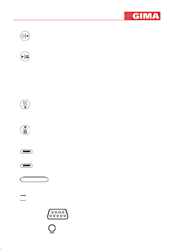
7. (Record/Back): Short time press it to enter into
SpO2
record list screen,
or to back to the previous level of menu.
8. (Alert indicator): If the probe is not well placed or disconnected,
or the measured value exceeds the preset alert limit value, then the alert indicator
will ash with orange color.
9. (Power saving mode indicator) If the device is set as power saving mode,
then the indicator lights up. And on measuring screen, the indicator ashes with
the pulse beep.
10. Icon: “SpO2”: ( ):
SpO2
Probe Connector.
11. Icon: “TEMP”: ( ): Temperature Probe Connector.
ENGLISH

42
12. ( ) USB connector. Used for data uploading or charging.
13. ( ): DC power input contact shoes with polarity indication. Used
for connecting external DC power input for charging the built-in rechargeable bat-
tery via the base.
1.2 Product Name and Model
Name: Handheld Pulse Oximeter
Model: SP-20
1.3 Structure
It consists of the main unit and
SpO2
probe.
(Note: with optional temperature prob, this Oximeter can make temperature meas-
urement.)
1.4 Features
• It is lightweight, small in size and easy to carry.
• Color LCD to display plethysmogram and parameters.
• Measure
SpO2
, Pulse Rate and Temperature simultaneously.
• PI (Perfusion Index) display is available.
• Up to 580 hours data storage for
SpO2
and PR and can be recalled.
• 16 user IDs for marking data and can be added.
• A built-on holder for convenient standing on desktop and display viewing.
• Real-time battery status display and low battery voltage indication.
• Auto power off is available.
• Audible and visual alert function is available.
• Data uploading to PC for management (Optional).
• Power saving mode is available.
1.5 Intended Use
This Handheld Pulse Oximeter is intended for measuring and recording the pulse rate,
functional oxygen saturation (
SpO2
) and temperature (optional). It is applicable for
detecting
SpO2
, pulse rate and temperature of adult and neonate patients in clinical
institutions and homes.
1.6 Working Environment
Operating temperature: 5~40°C
Operating humidity: 15%~93% (non-condensing)
Atmospheric pressure: 70kPa~106kPa
ENGLISH

43
2 Power Supply
1. Internal power supply with built-in battery:
Built-in battery specication: 2000mAh lithium battery.
2. External power from the AC power adapter:
Use the AC power adapter provided by the manufacturer. Make sure the mains
power supply is 100-240VAC with 50/60Hz.
Note: it’s recommended to use the AC power adapter provided by the manufacturer.
3. The Base:
Input: Micro USB connector, 5VDC/1A
Output: Contact pins. 5VDC/1A
Figure 2.1A Base--front view Figure 2.1B Base--top view
Description:
The base is used to hold the oximeter, and also for charging the oximeter. You can
charge the oximeter by the following methods:
1)
When the oximeter is held by the base, you can connect one end of the USB cable
to the USB connector on the back of the base marked with “DC 5V/1A”, and the
other end to the USB power source with output capacity of 5V DC/1A.
2) If the oximeter is not held by the base, then you can just connect one end of the USB
cable to the USB connector on the device marked with “ ”, and the other end
to the USB power source with output capacity of 5V DC/1A.
Notes:
1) During charging, if the oximeter is held by the base, please do not tilt the base
backwards too much, or the USB cable and the USB connector may be damaged.
2) Put the device into the base properly, and pay attention to the polarity markings, as
shown in gure 2.2.
Polarity markings
Micro USB connector
ENGLISH

44
Figure 2.2 Connection between oximeter and base
Base
Oximeter
Insert the oximeter
into the base by this
direction
ENGLISH

45
3 Make Measurement
3.1
SpO2
Measurement
Operation procedures:
1. Connect the
SpO2
probe to the connector on the upper-side of the device marked
with “
SpO2
”. (Note: When disconnecting the connector, be sure to hold the head of
the connector rmly and pull).
2. The red blinking light inside the clip of the
SpO2
probe indicates a successful con-
nection.
3. Insert one nger (index nger is preferred, the nail should be not too long) into the
clip of the probe according to the nger mark,as shown in gure 3.1.
4. The device will begin to take the measurement, and the measured result will be
displayed on the screen, as shown in gure 4.2.
Figure 3.1 demonstration for SpO2probe
Safety instructions for SpO2measurement
Long term use of the
SpO2
probe on the same place may result in discomfort or
pain, especially for those with microcirculatory problems. It is recommended that
the probe should NOT be applied to the same place for over two hours, change the
measurement site periodically and when necessary.
When the ambient temperature is over 35℃, please change the measuring site every
two hours; when the ambient temperature is over 37℃, please do NOT use the
SpO2
sensor, as using in high temperatures can cause burns.
Do NOT place the
SpO2
probe on a nger with edema or fragile tissue.
Do NOT put the
SpO2
probe and pressure cuff on the same limb, otherwise the
blood pressure measurement may affect the
SpO2
measurement.
The device is calibrated to display functional oxygen saturation
Do NOT allow the sensor cable to twist or bend.
Check the
SpO2
sensor and cable before use. Do NOT use a damaged
SpO2
sen-
sor.
When the temperature of the
SpO2
sensor is abnormal, do not use it further.
ENGLISH

46
Remove nail polish or other cosmetic products from the ngernail.
The ngernail should be of normal length.
The
SpO2
sensor cannot be immersed into water, liquid or cleanser.
The
SpO2
sensor can be repeatedly used. Please clean and disinfect before reuse.
Connector with the label “
SpO2
” can only be connected with
SpO2
probe, and
connector with the label “TEMP” can only be connected with the temperature
probe.
3.2 Temperature Measurement (optional)
The infrared temperature probe is a delicate transducer. To operate please follow these
steps and procedures. Failure to accurately operate may cause damage to the probe.
The infrared temperature probe is as shown in gure 3.2.
Please place the infrared temperature probe in a stable ambient temperature for 30
minutes before taking a measurement.
Figure 3.2 the infrared temperature probe
Operation procedure:
1. Connect the infrared temperature probe to the connector on the upper side of
device marked with “TEMP”.
2. When the screen shows as the big display screen in gure 3.2 and the temperature
unit “°C” is blinking, the user can begin to take the measurement.
3. Insert the tip of the temperature probe into the earhole and press the measuring key
to start the measurement. A short beep means the measurement has nished and
the result will be displayed on the big display screen on temperature probe and the
display screen of the Oximeter.
Measuring tip of
temperature probe
Temperature
Probe Cover
Small screen
Power on/off key
Battery cover
Measuring key
Big display screen
ENGLISH

47
Nota:
• If the temperature probe detects a hardware failure, the display screen on the infra-
red temperature probe will show “Err” and will not enter into measurement mode.
• The infrared temperature probe will switch to standby state automatically if there is
no operation for 1 minute. If a further measurement is needed, press the measuring
key and repeat step 2 and step 3.
• Normal body temperature varies depending on the position/area the measurement
is taken from. The following table shows the varying temperature ranges of the dif-
ferent body positions.
Temperature varying range at different body positions:
Safety Instruction for Temperature Measurement
Do NOT take a measurement when the patient is moving.
Patients with tympanitis or otitis problems should NOT use this device.
When the infrared temperature probe is connected to the device, the probe will
consequently be at power-on status, therefore pressing the power on/off key on
the temperature probe will not cause any effect.
4 Operation
4.1 Power on/off the Oximeter
• Long pressing “ ”Power/Left key for 1~2 seconds, then the oximeter will be
powered on. The oximeter will do self-test and then the software version and warn-
ing message “Professional attendance is required for continuous monitoring!” will be
shown on the screen, as shown in gure 4.1 (refer to your oximeter for actual version).
Figura 4.1
Arm 34,7 ~ 37,3°C
Oral 35,5 ~ 37,5°C
Rectal 36,6 ~ 38,0°C
Ear 35,8 ~ 38,0°C
ENGLISH

48
4.2 Default Display Screen
Press “ ” power key for 2 seconds to start up the Oximeter, then the screen will
display the default screen, as shown in Figure 4.2.
Figure 4.2A Default Display Screen---in vertical
Description:
• During measurement, if the nger is not inserted properly, or the probe is not con-
nected or the probe is off from the nger, then “Check Probe” message prompts and
keeps blinking on the screen, and “bibibi...” alert sound appears simultaneously.
Alert sound is sustaining for about 3 minutes, and if there is no any key operation in
this period, then the device will power off automatically (if the auto power off func-
tion is enabled).
• During measurement, longtime pressing Auto-rotate/Up key “ ”, then
the Auto-rotate white icon “ ” appears on the upper right corner of the
Patient type Battery indicator
SpO2mark
SpO2high/low
limit setting
value
SpO2value
Pulse rate
mark and unit
HR high/low limit
setting value
Perfusion index
Current time
Pulse Strength
bar-graph
Pulse symbol
Pulse rate value
TEMP value
Plethysmogram
Sound indicator
Recording mode
Wireless icon
User ID
Auto-rotate icon
Auto power off
disable icon
ENGLISH

49
screen, it means the auto rotation function is enabled, if you place this oxime-
ter horizontally, then the display shows in horizontal, as shown in gure 4.2B.
Figure 4.2B Default Display
Screen---in horizontal
•
Sound indicator “ ” means that the global sound is disabled, the user can enable
the global sound by longtime pressing “ ”. key. Longtime pressing “ ”
key again can disable the global sound, that’s to say, the speaker is turned off at all,
therefore, no pulse beep sound, no audible alert and no key click sound.
• If the global sound is enabled by longtime pressing “ ”, key, then during the
measurement, over-limit alert event or probe off event can activate the audible alert.
Refer to Section 6.2 for detailed alert indication sound.
• If the memory is full, the corresponding memory full icon appears on the screen:
“ ”, means temperature memory is full,“ ” means
SpO2
spot-check record
memory is full; “ ”, means
SpO2
trend record memory is full. No display of the
icon means the current corresponding storing space is not full. If the memory is full,
the data storing will continue in such way the new record will overwrite the oldest
record, so that it’s recommended to upload the stored data into the computer in
time.
4.3 Menu
On the default measuring screen, short time press “ ”Menu/Conrm key for
entering into main menu screen (as shown in Figure 4.3).
ENGLISH

50
There are 9 functional icons in main
menu screen, press Up/Down/Left/
Right key can move the cursor to
make selection and press “
”Menu/Conrm key again to conrm
the selection.
• User ID: Add new or edit the current
User ID.
• User: Select patient type, “Adult”
and “Neonate” for option.
Note: when the device is set to the ne-
onate patient type, then the User icon
“ ”
turns to grey
“”, and
the patient type on upper left corner
turns to pink “ ”.
• Recording mode: Select the data
recording mode, “Spot-check Re-
cord” and “Trend Record” for option.
• SpO2record: Recall and review the
records stored on the oximeter, two
types of record for option: “Spot-
check Record” and “Trend Record”,
see Section 4.4 for details.
• TEMP Record: Review the temper-
ature record list.
• Date: Set the time and date, see Section 4.3.6 for details.
• Settings: Set the system parameter, including brightness, sound volume, display
language, power saving mode etc., see Section 4.3.7 for details.
• Alerts: Set the low alert limit for
SpO2
and the high/low alert limit for PR, see Section
4.3.8 for details.
• Help: To view the tips information of
SpO2
measurement and temperature measure-
ment, see Section 4.3.9 for details.
4.3.1 User ID
On main menu screen, move the cursor on “User ID” and press Conrm key “ ”,
then the oximeter enters into User ID Setup screen, as shown in gure 4.4.
Figure 4.3 Main menu
ENGLISH

51
Figure 4.4A User ID setup screen
Move the cursor on “Edit” and press Conrm
key “ ”; when the cursor turns to blue,
then the user can edit the User ID, and move
the cursor on “OK” to conrm the edit, the edit
screen is as shown in gure 4.4B.
Figure 4.4B User ID edit screen
4.3.2 User
On main menu screen, move the cursor on “User” and press Conrm key “ ”,
then the oximeter enters into Patient type Setup screen, as shown in gure 4.5.
Figure 4.5 Patient type setup screen
ENGLISH

52
4.3.3 Recording Mode
On main menu screen, move the cursor on
“Recording Mode” and press Conrm key
“ ”, then the oximeter enters into Re-
cording Mode Setup screen, as shown in gure
4.6.
Figure 4.6 Recording mode setup screen
Note: When selecting “Spot-check Record” for data recording, the measuring time
should last over 10 seconds to get one spot-check reading, or no reading value will
not be recorded in Spot-check data record; When selecting “Trend Record”, the
measuring time should exceed 30 seconds, or no one record will be recorded in Trend
data record list.
4.3.4 SpO2Record
On main menu screen, move the cursor on “
SpO2
Record” and press Conrm key
“ ”, then the oximeter enters into
SpO2
record review method selecting screen,
as shown in gure 4.7.
Figure 4.7 SpO2 record review method selecting screen
Refer to Section 4.4 for details.
4.3.5 TEMP Record
On main menu screen, move the cursor on “TEMP Record” and press Conrm key
“ ”, then the oximeter enters into temperature record list screen, as shown in
gure 4.8.

53
Figure 4.8 TEMP record list screen
4.3.6 Date
On main menu screen, move the cursor on
“Date” and press Conrm key “ ”, then
the oximeter enters into date setup screen, as
shown in gure 4.9.
Figure 4.9 Date setup screen
Date setting procedure:
1) Move the cursor stays on the Year of the date, press Conrm key “ ”to active
Year option, the cursor ashes on the Year of the date.
2) Press Up/Down key to adjust Year.
3) Press “ ” (Conrm) key to conrm and exit from date setting.
4) The procedures of adjusting Month, Day, Hour, Minute and Second value are the
same with Year adjustment.
Date Format: DD-YY-MM; Time Format: HH:MM:SS

54
Note: The setting operations of other parameters (such as User ID, User, Auto Power
Off, Power Saving etc.) are the same with date setting.
4.3.7 Settings
On main menu screen, move the cursor on “Settings” and press Conrm key “ ”,
then the oximeter enters into system setting screen, as shown in gure 4.10.
Figura 4.10
System
setting screen
Description:
• Brightness: To set the brightness of backlight, 6 levels for optional, the factory
default is level 3, as shown in gure 4.10A.
• Volume: To set the sound volume (including alert sound, pulse beep sound and key
click sound), 6 levels sound volume for optional, the factory default is level 3, as
shown in gure 4.10B.
• Pulse beep: To turn on/off pulse beep, the factory default is “On”, as shown in gure
4.10C. If the global sound is enables by longtime pressing , key, and the pulse
beep is set to “On” option, and when there is no over-limit event, then pulse beep
sound can be heard during
SpO2
measurement.
• Language: This oximeter provides the display with two languages: English and Sim-
plied Chinese, the factory default is “English”, as shown in gure 4.10D.
• Auto power off: To turn on/off the Auto Power Off mode, the factory default is “On”,
as shown in gure 4.10E.
• Wireless: To turn on/off the wireless connection function, the factory default is “On”,
as shown in gure 4.10F.
• Power saving mode: To turn on/off the Power Saving mode, the factory default is
“On”, as shown in gure 4.10G.
• TEMP unit: To set the temperature unit, “°C (Celsius)” and “°F (Fahrenheit)” for
ENGLISH

55
option, the factory default is “°F”, as shown in gure 4.10H.
• Factory Default: Enter into the factory default setting, as shown in gure 4.10I.
• Version: For viewing version number of the software, as shown in gure 4.10J.
• Demo: Enter into the Demonstration mode, as shown in gure 4.10K.
Figure 4.10A Brightness setup Figure 4.10B Volume setup
Figure 4.10C Pulse beep setup Figure 4.10D Language setup
Figure 4.10E Auto Power OFF setup Figure 4.10F Wireless setup
Figure 4.10G Power Saving setup Figure 4.10I TEMP unit setup
ENGLISH

56
Figure 4.10H Version info Figure 4.10J Default setting
Notes:
• When the Auto Power Off is set to “On” op-
tion, if there is no key operation for 3 minutes,
then the oximeter will power off automatically.
• When the Power Saving Mode is set to “On”
option, during the measurement, if there is no
key operation for 1 minute, the screen dis-
play will be dim for power saving. The display
brightness will resume to normal condition by
pressing any key.
Figura 4.10K Modalità Demo
4.3.8 Alerts
On main menu screen, move the cursor on “Alerts”
and press Conrm key “ ”, then the oxime-
ter enters into alerts setting screen, as shown in
gure 4.11.
Figure 4.11 Alerts setting screen
ENGLISH

57
• SpO2Lo-Limit:
SpO2
low limit setting; range: 50%~99%, the step is 1%. The fac-
tory default value for adult is 90% and 95% for Neonate.
• PR Hi-Limit: High limit setting of pulse rate; range: 100~240bpm. From 100 to 150,
the step is 1bpm, and from 150 to 240, the step is 5bpm. The factory default value
for adult is 120bpm and 160bpm for neonate.
• PR Lo-Limit: Low limit setting of pulse rate; range: 30~99bpm, and the step is
1bpm. The factory default value for adult is 50bpm and 60bpm for neonate.
Note: When the
SpO2
reading is lower than or equal to the preset alert setting or the
PR reading is higher than or equal to the preset high limit or the PR reading is lower
than or equal to the preset low limit, then the over-limit alert event will be activated,
that’s, the alert sound “bibibibi...” occurs, and the corresponding reading(s) blinks.
When measured on neonate, if the
SpO2
reading is lower than or equal to the preset
alert setting for 10 seconds, then the alert sound and blinking display will be activated.
4.3.9 Help
On main menu screen, move the cursor on “Help” and press Conrm key “ ”,
then the oximeter help information screen, which shows
SpO2
and temperature meas-
urement tips, as shown in gure 4.12.
Figure 4.12 Help information Figure 4.12 Help information
---SpO2measurement ---TEMP measurement
Help
1/2
Note: Make sure the light
emitting and receiving ends
are aimed at each other. V
Baby L
Infant Pediatric
Note: Remove temperature probe
cover, insert the probe into earhole,
then press key to start measurement.
Help 2/2
ENGLISH
Other manuals for OXY 110
1
This manual suits for next models
2
Table of contents
Other Gima Medical Equipment manuals

Gima
Gima 27406 User manual

Gima
Gima MT PROFESSIONALE User manual

Gima
Gima PRIMALED User manual

Gima
Gima CLAR Parts list manual

Gima
Gima OXY-PED Parts list manual

Gima
Gima VISIO 2000 User manual

Gima
Gima 31107 Parts list manual

Gima
Gima SKS002-W User manual

Gima
Gima 34277 User manual

Gima
Gima KS-H1N User manual
Popular Medical Equipment manuals by other brands

Aspire
Aspire ULTIMATE 8 user manual

Meridian Bioscience
Meridian Bioscience BreathID Smart quick start guide

mk-dent
mk-dent AM1014 instruction manual

Terragene
Terragene BIONOVA IC10FRLCD Instructions for use

Electromed
Electromed SmartVest Clearway instruction manual

Kodak
Kodak DirectView CR 825 ADJUSTMENTS AND REPLACEMENTS