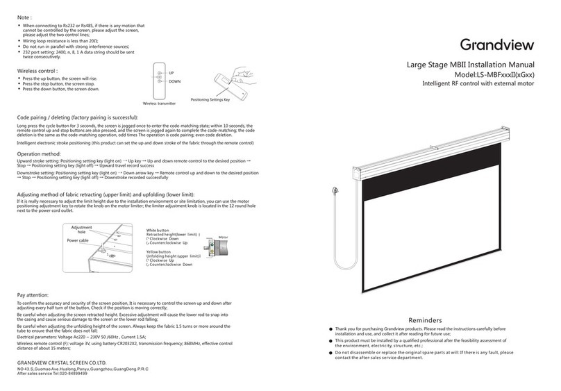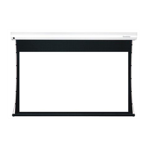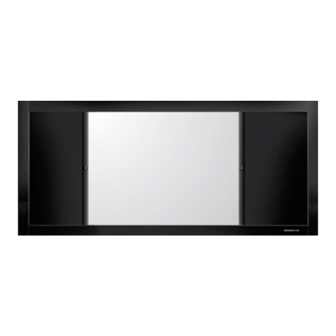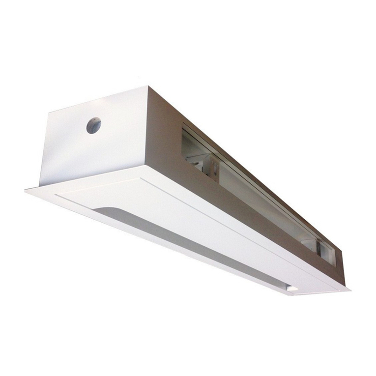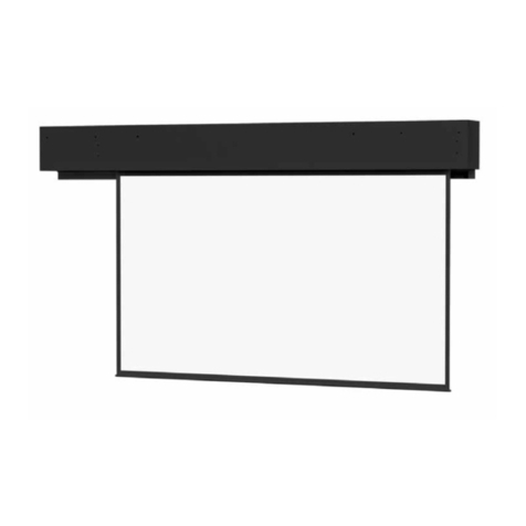
Screen structure diagram
Ⅱ.Functions and Instructions
This product has three control methods
a.Manual Control Button
b.12V Tigger Control
c.RF Remote Control
a.Manual Control
The Manual Control Button is located on the power
port side of the casing. Pressing the button will
command the screen to extend, pressing the button
will command the screen to stop, then again to
retract, then stop in sequence.
b.12V Tigger Control
Connect the 12V Tigger Port and the 12V port with a 12V
trigger cable; the projection screen is then synchronized
with the projector (when the projector is powered on,
the screen will automatically extend to set position; when
the projector is powered off, the screen will retract).
Connecting Parts
Tab Tension
Fabric
Decorative Door
End Cap
Casing
Fabric Support Bar
Upper Support Arm
Joint
Lower Support Arm
Side View
c. RF Remote Control
● Press the Up button, Decorative door opens, screen extends
to set position.
● Press the Stop button, screen will pause.
● Press the Down button, the screen will retract and Decorative
door closes.
● Press the Jog Up button or the Jog Down button to extend or
retract the screen (usually used when setting extension or
retraction limit).
■ Wireless Remote 1pcs
Power Port
Side Handle
Manual Control Button
IR Port(φ3.5)
12V Tigger Port(φ2.5)
Stop
Stop
Up Down
Manual Cycle
Manual Control Button
12V Tigger Port
Projector
IR Port(φ3.5)
Flexible Door Opening And
Closing Device
Accessories
■Power Cable 1pcs ■ 12V Trigger Cable 1pcs
■ Limit Adjustment Tool 1pcs
■ Brush 1pcs
■Adjustable Mounting Bracket 2pcs
(Optional)
■ User Manual 1pcs
■ Allen Key 1pcs ■ M5X10mm Combination Screw 6pcs
■ ø5X40mmRound Head Self-Tapping Screw 10pcs
Plastic Expansion Tube 10pcs
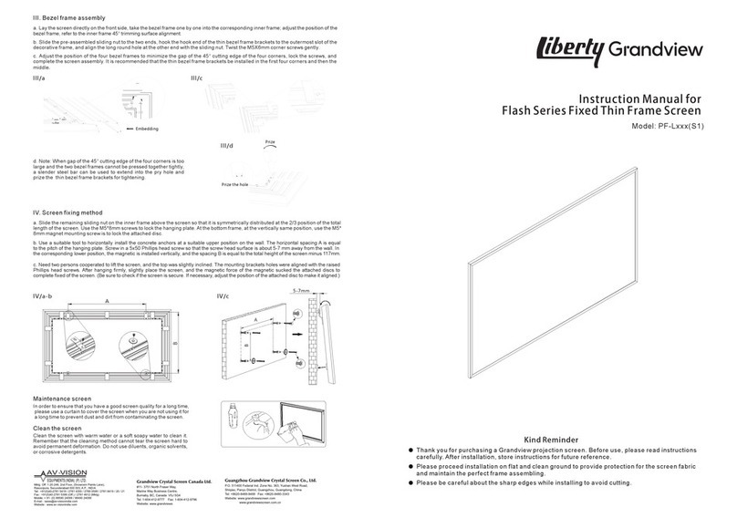
Ⅰ.Screen Installation Guidelines
① Scenario 1
Lay the projection screen flat on the cabinet: leave at least 4mm of room from
the wall for the decorative door’s operation. Fully extend the projection
screen using the remote, adjust the tilt of the projection screen using the Level
Adjustment Nobs under the casing.
Caution: Projection screen might tip over if there is too much tilt.
② Scenario 2
a.Measure the total length of the casing, measure the height where the bottom
of the projection screen will be placed, and mark it on the wall. See value “A”
on the table for the recommended distance between the two Adjustable
Brackets. Line up the top of the Adjustable Bracket with the bottom of the
projection screen (mark that was made on the wall).
Ⅱ
/a-b
UP
STOP
DOWN
JOG UP
JOG DOWN
Positioning setting key
AC123Wireless remote control
Paper Clip
(not included)
Ⅱ
/c
Level Adjustment Nob
Turn the Level Adjustment
Nobs under the casing
Adjusting the tilt of the
projection screen
distance to wall≥4mm
Cabinet
Ⅰ/①
Top
center line
Marking line at the bottom of the casing
Wall or Cabinet
Distance A
b.Drill the 4 holes for each bracket on the wall, install an Expansion Fixture in each hole. Place the Adjustable Brackets
against the wall lining up with the Expansion Fixtures and tighten usingφ5*40 Tapping Screws.
c.Adjust the T-Nuts on the Adjustable Bracket so that they are parallel with the wall (see diagram), place the projection
screen on the Adjustable Brackets, adjust the projection screen horizontally to the desire position, tighten the T-Nuts
from under the Adjustable Brackets to lock in place. (T-Nuts are installed for front installation in default, user can install
the T-Nuts to the Reverse Mounting Holes when needed for reversed installation)
d.Connect to power, fully extend projection screen; observe for tilt, adjust tilt using the Allen Key to desire position to
finish installation.
Ⅰ/② c-d
Ⅰ/① a-b
size (diagonal)
Distance A (mm)
92”(16:9)
1630
100”(16:9)
1810
110”(16:9)
1910
120”(16:9)
2130
Level
T-Nut
T-Nut
Insert to
notch
T-Nut
Spin to
Tighten
±1.5° Adjustable
Reverse
Mounting Holes
Front Installation Reversed Installation
70109
152
