manuals.online logo
Brands
  1. Home
  2. •
  3. Brands
  4. •
  5. Grandview
  6. •
  7. Projection Screen
  8. •
  9. Grandview FC-FH-MI II Series User manual

Grandview FC-FH-MI II Series User manual

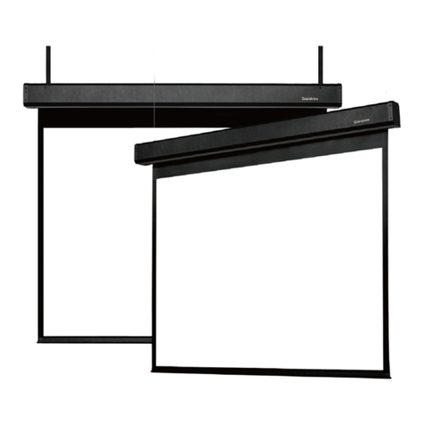
Motorized Tabletop Screen Installation Manual-HII
Model:FC-FH-MIxxxⅡ
Caution
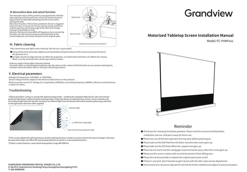
Ultra-short throw ambient light rejection fabric:DO NOT USE RAG OR PAPER TOWEL TO WIPE
●Use brush provided to brush lightly horizontally along the texture of the screen to remove dust or other fine particles.
●For light-colored smudges that affects viewing, try removing with residue-free tape.
Ⅲ.Maintenance
Non ambient light rejection regular throw fabric:
Use clean water with mild detergent to gently wipe the stains on the surface of the fabric (do not use corrosive detergents).
Only retract the projection screen when the fabric is completely dry.
Ⅳ.Electrical parameters
Voltages & Frequencies: 110V/60Hz or 220V/50Hz(Actual voltage shall be subject to the electrical label shown on the product)
Wireless remote control (F): Voltage 3V, using battery CR2032X2, transmitting frequency; 868MHz, effective control distance is about
15 meters.
GUANGZHOU GRANDVIEW CRYSTAL SCREEN CO.,LTD.
A: No.43 S, Guomao Ave.Hualong,Panyu,Guangzhou,Guangdong,P.R.C
T: 020-84899499
Troubleshooting
Ambient light
Reflection image light
Ultra short throw projection light
①Black grid fabric surface is carved with optical grating tooth,enabling the targeted reflection for ultra short throw projector light
beam and forming the viewing image. Projection theory as below picture shown: Screen adsorbs only the ambient light from the top
but resistance to ambient light from horizontal side will be weaken,please pay attention to the light beam direction when applied.
②The screen adpots the splicing process,and the splicing line has a certain curvature due to the source of upper and lower tension,
which does not affect the actual projected picture.which is a normal phenomenon.
③Fabric surface flatness: Lower black drop perfect range:250-350mm
USB Serial Port (COM3) Properties
General Port Settings Driver Details Events
Baud Rate: bits/s (B): 2400
Data Bits:(D): 8
Parity (P): None
Stop Bits: Stop Bits (S): 1
Flow Control (F): None
Advanced (A)... Restore Defaults (R)
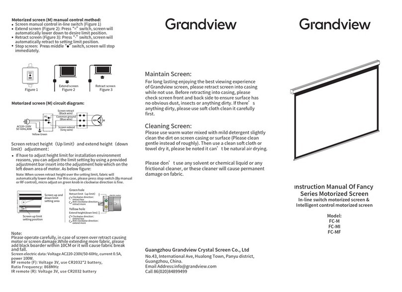
Screen retraction height (lower limit) and extension height (upper limit) adjustment method:
●If it is necessary to adjust the limit height due to installation environment or other constraints, you can adjust the upper and lower
limits by using the Limit Adjustment Tool provided. As shown in the following diagram:
Green knob:
Retraction height (lower limit)
Clockwise adjustment: increase limit (up)
Counterclockwise adjustment: decrease limit (down)
Yellow knob:
Extension height (upper limit)
Clockwise adjustment: decrease limit (down)
Counterclockwise adjustment: increase limit (up)
Motor
Limit Adjustment
Hole
d.RS485/RS232 Control:
The control output port is connected to an RJ45 (8P8C) plug, with lines 1 and 2 being
the control lines. For RS485 control connection, line 1 is D-, and line 2 is D+. For RS232
control connection, please refer to the diagram shown:
RS485/RS232 port settings:
●Baud rate: 2400;
●Data bits: 8 bits;
●Parity: None;
●Stop bits: 1
Hexadecimal control codes:
●Retract: FF EE EE EE DD
●Stop: FF EE EE EE CC
●Extend: FF EE EE EE EE
Some central control devices require an address code to be set:
FF EE EE EE AA
Note:
●When connecting RS232 or RS485, if the screen cannot be controlled to perform related actions, please swap the two control lines.
●The wiring loop resistance should be less than 20Ω.
●Do not run wiring parallel to strong interference sources.
OK Cancel
● Please tear out all the blue tape from the trap door before powering on.
● Please do not reach into the casing gap to prevent hands injury when the screen goes up.
● Please put the screen in place with no wind to prevent it from flling over.
● Please Do not disassemble or replace the original spare parts at will.
Thank you for choosing Gandview products. Please read the manual carefully before installation and use.
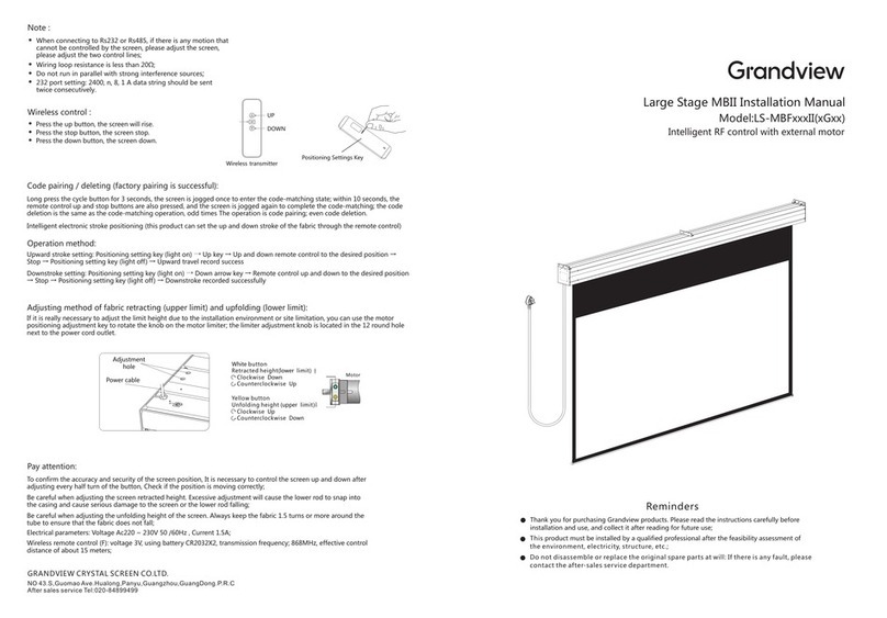
b.IR Remote Control
●Press the Up button, Decorative door opens, screen extends to set position.
●Press the Stop button, screen will pause.
●Press the Down button, the screen will retract and Decorative door closes.
●Press the Jog Up button or the Jog Down button to extend or retract the
screen (usually used when setting extension or retraction limit).
Pairing/Unpairing(Remote have been paired at factory)
Disconnect the power supply for 10 seconds and then reconnect, press the
Up and Stop button simultaneously within 10 seconds of reconnection. The
motor will rotate forward and then backward once signaling a successful
pairing.
Repeat this process to unpair a remote. Repeat the process an odd number
of times to pair, and an even number of times to unpair.
Ⅱ/b
Ⅱ.Functions and Instructions
This product has four control methods:
a.Manual Control Button
b.IR Remote Control
(IR Receiver Needed)
c.RS485/RS232 Control
d.Dry Contact
a.Manual Control
The Manual Control Button is located on the power port side of the casing.
Pressing the button will command the screen to extend,
pressing the button will command the screen to stop, then again to retract,
then stop in sequence.
Connecting parts
Tab Tension
Fabric
End Cap
Casing
Upper Support Arm
Joint
Lower Support Arm
Side View
Stop
Stop
Up Down
Manual
Cycle
Accessories
Ⅰ.Screen Installation Guidelines
Ⅱ/a
Spring-Loaded Cover
Power Port
Manual Control Button
External Infrared Receiver
Fabric Support Bar
8P8C Communication Port
Level Adjustment Nob
① Scenario 1
Lay the projection screen flat on the cabinet: leave at least 4mm of
room from the wall. Fully extend the projection screen using the remote,
adjust the tilt of the projection screen using the Level Adjustment Nobs
under the casing.
Caution: Projection screen might tip over if there is too much tilt.
Ⅰ/①
②Scenario 2
a.Measure the total length of the casing, measure the height where the
bottom of the projection screen will be placed, and mark it on the wall.
See value “A” on the table for the recommended distance between
the two Adjustable Brackets. Line up the top of the Adjustable Bracket
with the bottom of the projection screen (mark that was made on the
wall).
b.Drill the 4 holes for each bracket on the wall, install an Expansion
Fixture in each hole. Place the Adjustable Brackets against the wall lining
up with the Expansion Fixtures and tighten usingφ5*40 Tapping Screws.
c.Adjust the T-Nuts on the Adjustable Bracket so that they are parallel with the wall (see diagram), place the projection screen on the
Adjustable Brackets, adjust the projection screen horizontally to the desire position, tighten the T-Nuts from under the Adjustable
Brackets to lock in place. (T-Nuts are installed for front installation in default, user can install the T-Nuts to the Reverse Mounting Holes
when needed for reversed installation)
d.Connect to power, fully extend projection screen; observe for tilt, adjust tilt using the Allen Key to desire position to finish installation.
Ⅰ/② a-b
Top
center line
Wall or Cabinet
Ⅰ/② c-d
Size(diagonal)
Distance A (mm)
92”(16:9)
1740
100”(16:9)
1920
110”(16:9)
2020
120”(16:9)
2240
Distance A
101
151
112
Turn the Level Adjustment
Nobs under the casing
Adjusting the tilt of the projection screen
distance to wall≥4mm
Cabinet
133 (16:9)
2410
”
Level
T-Nut T-Nut
T-Nut
±1.5° Adjustable
Front Installation Reverse Installation
Reverse
Mounting
Holes
RS485/RS232 Control
External Infrared Receiver
Manual Control Button
c.Dry contact control:
The control output port is connected to an RJ45 plug, with lines 4, 5, 7, and
8 being the control lines, starting from the left side.
Up Down
Screen structure diagram
Marking line at the bottom of the casing
Common StopFunction
Line
Up
Down
Common
Stop
■ Power Cable 1pcs ■ IR Remote 1pcs ■ Adjustable Mounting Bracket 2pcs
(Optional)
■ Limit Adjustment Tool 1pcs
■ IR Receiver 1pcs
■ Allen Key 1pcs
■ 10.Socket Screwdrive 1pcs
■ M5 Anti-Slip Nuts 6pcs ■ ø5X40mm Round Head Self-Tapping Screw 10pcs
Plastic Expansion Tube 10pcs
■ User Manual 1pcs
■ Brush 1pcs
IR Receiver
30°
Iindicator ligh
Up
Stop
Down
JOG UP
JOG DOWN
Model:AC-127
Other Grandview Projection Screen manuals

Grandview CB-Sxx User manual

Grandview

Grandview CB-Sxx User manual

Grandview GVFA100V User manual

Grandview

Grandview GVFA100V User manual

Grandview LF-PHxx(DY) User manual

Grandview

Grandview LF-PHxx(DY) User manual

Grandview Edge R1 Series User manual

Grandview

Grandview Edge R1 Series User manual

Grandview Super Mobile LS-E Series User manual

Grandview

Grandview Super Mobile LS-E Series User manual

Grandview LF-VMF-77 User manual
Grandview

Grandview LF-VMF-77 User manual

Grandview Edge R7 User manual

Grandview

Grandview Edge R7 User manual

Grandview FC-FHMF Series User manual

Grandview

Grandview FC-FHMF Series User manual

Grandview CB-Mxx User manual

Grandview

Grandview CB-Mxx User manual

Grandview LF-PP series User manual

Grandview

Grandview LF-PP series User manual

Grandview Large Stage MBII User manual

Grandview

Grandview Large Stage MBII User manual

Grandview Skyshow Series User manual

Grandview

Grandview Skyshow Series User manual

Grandview GRUC040V User manual

Grandview

Grandview GRUC040V User manual

Grandview Large Sky-Show User manual

Grandview

Grandview Large Sky-Show User manual

Grandview LEGACY Series User manual

Grandview

Grandview LEGACY Series User manual

Grandview PE-Y (R7)15 Series User manual

Grandview

Grandview PE-Y (R7)15 Series User manual

Grandview CB-Pxx User manual

Grandview

Grandview CB-Pxx User manual

Grandview Edge R3 PE-L Series Instruction Manual

Grandview

Grandview Edge R3 PE-L Series Instruction Manual

Grandview Sky-Show User manual

Grandview

Grandview Sky-Show User manual

Grandview DIAS DI-M Series User manual

Grandview

Grandview DIAS DI-M Series User manual

Grandview Cyber CB-MI Series User manual

Grandview

Grandview Cyber CB-MI Series User manual

Grandview FC-FHP-MI Series User manual

Grandview

Grandview FC-FHP-MI Series User manual

Grandview EL-Pxx User manual

Grandview

Grandview EL-Pxx User manual

Grandview LF-Mxx User manual

Grandview

Grandview LF-Mxx User manual

Popular Projection Screen manuals by other brands

Milestone Da-Lite Slimline Electrol Instruction book

Milestone

Milestone Da-Lite Slimline Electrol Instruction book

Cirrus Screens Harbour 2 manual

Cirrus Screens

Cirrus Screens Harbour 2 manual

Elite Prime Vision EDGE FREE Dark Star eFinity Series user guide

Elite Prime Vision

Elite Prime Vision EDGE FREE Dark Star eFinity Series user guide

TIBURN FLIP HUB 55 Operation guide

TIBURN

TIBURN FLIP HUB 55 Operation guide

Music & Lights FullScreen SCSP Series user manual

Music & Lights

Music & Lights FullScreen SCSP Series user manual

SI ZERO EDGE PRO owner's manual

SI

SI ZERO EDGE PRO owner's manual

Fasttel Cult user manual

Fasttel

Fasttel Cult user manual

HELGI CORI Instruction and maintenance

HELGI

HELGI CORI Instruction and maintenance

Samo lineabeta Open B4600 Assembly instruction

Samo

Samo lineabeta Open B4600 Assembly instruction

Avers Screens Akustratus 2 Tension user manual

Avers Screens

Avers Screens Akustratus 2 Tension user manual

Lekolar 81214 manual

Lekolar

Lekolar 81214 manual

Elite Screens Kestrel Series instructions

Elite Screens

Elite Screens Kestrel Series instructions

Verano SCREEN V585 installation manual

Verano

Verano SCREEN V585 installation manual

Da-Lite TENSIONED DIRECTOR ELECTROL Instruction book

Da-Lite

Da-Lite TENSIONED DIRECTOR ELECTROL Instruction book

Elite Screens Evanesce Tension Series user guide

Elite Screens

Elite Screens Evanesce Tension Series user guide

Optoma ALR120 installation guide

Optoma

Optoma ALR120 installation guide

Elite Screens Spectrum Series user guide

Elite Screens

Elite Screens Spectrum Series user guide

EluneVision EV-S-1.0 user guide

EluneVision

EluneVision EV-S-1.0 user guide

manuals.online logo
manuals.online logoBrands
  • About & Mission
  • Contact us
  • Privacy Policy
  • Terms and Conditions

Copyright 2025 Manuals.Online. All Rights Reserved.