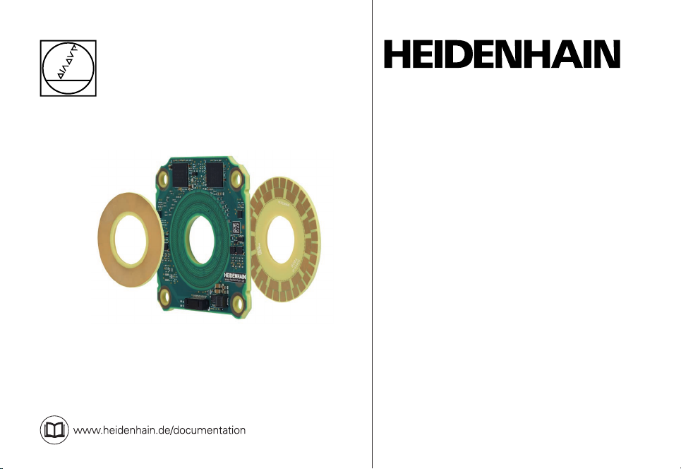
HEIDENHAIN KCI 120 Dplus User manual
Other HEIDENHAIN Media Converter manuals

HEIDENHAIN
HEIDENHAIN ERO 1225 User manual

HEIDENHAIN
HEIDENHAIN ECN 1324 S User manual

HEIDENHAIN
HEIDENHAIN IK 5000 QUADRA-CHEK User manual

HEIDENHAIN
HEIDENHAIN ECN 1325 EnDat22 User manual

HEIDENHAIN
HEIDENHAIN ECN 1313 EnDat01 User manual

HEIDENHAIN
HEIDENHAIN LIDA 473 User manual

HEIDENHAIN
HEIDENHAIN AK ECA 4410 User manual

HEIDENHAIN
HEIDENHAIN ERN 1321 User manual

HEIDENHAIN
HEIDENHAIN LIF 481R User manual

HEIDENHAIN
HEIDENHAIN LIP 372 User manual

HEIDENHAIN
HEIDENHAIN ROD 431.025 User manual

HEIDENHAIN
HEIDENHAIN ECI 119 EnDat01 User manual

HEIDENHAIN
HEIDENHAIN LIF 171R User manual

HEIDENHAIN
HEIDENHAIN KGM 181 User manual

HEIDENHAIN
HEIDENHAIN AK ERP 10 Series User manual

HEIDENHAIN
HEIDENHAIN ERA 7480 User manual

HEIDENHAIN
HEIDENHAIN LC 4 5 Series User manual

HEIDENHAIN
HEIDENHAIN LC 2 1 Series User manual

HEIDENHAIN
HEIDENHAIN ECI 1119 User manual

HEIDENHAIN
HEIDENHAIN Ron 705 User manual