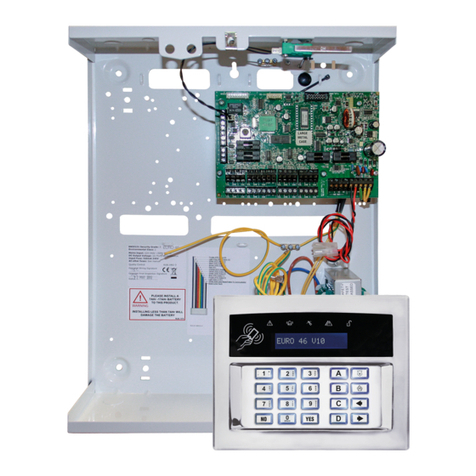
EURO 280 Installation Manual
Page: 2
Contents Page
1. System Overview .........................................................................................................................................................................................................3
1.1 System Overview ...................................................................................................................................................................................................3
1.2 The Devices............................................................................................................................................................................................................4
1.3 EURO 280 Input Mapping Table: ........................................................................................................................................................................... 6
1.4 EURO 280 Output Mapping Table:.........................................................................................................................................................................7
2. Installation ................................................................................................................................................................................................................... 8
The Printed Circuit Board................................................................................................................................................................................................. 9
2.3 Technical Specification ........................................................................................................................................................................................10
2.1 Important Installation Notes ...............................................................................................................................................................................11
2.2 Communication ATE Loom .................................................................................................................................................................................. 12
2.3 Battery Connection.............................................................................................................................................................................................. 12
2.4 AC Mains Supply Connection...............................................................................................................................................................................12
2.5 Engineer Keypad Connection...............................................................................................................................................................................13
3. Input Connections......................................................................................................................................................................................................14
3.1 Default Grade 2 DEOL (Double End of Line) Input Wiring....................................................................................................................................15
3.2 Grade 3 Mask/Fault Input Wiring ........................................................................................................................................................................15
4. Output (PGM) Connections........................................................................................................................................................................................16
4.1 Negative Applied Wiring......................................................................................................................................................................................16
4.2 Positive Applied Wiring........................................................................................................................................................................................ 16
5. External Sounder Connections................................................................................................................................................................................... 17
5.1 Grade 3 External Sounder Wiring ........................................................................................................................................................................17
5.2 Grade 2 External Sounder Wiring with a Grade 3 Bell .........................................................................................................................................17
5.3 Grade 2 External Sounder Wiring ........................................................................................................................................................................18
6. Connecting the EURO Peripherals..............................................................................................................................................................................19
6.1 Connecting the LCD Keypad (EURO-LCDPZ)......................................................................................................................................................... 19
6.2 Connecting the Internal Tag Reader (EURO-PROXI – EUR-107)...........................................................................................................................22
6.3 Connecting the External Proximity Reader (EURO-PROXE - EURO-108X)............................................................................................................ 24
6.4 Connecting the Zone Expander Module (EURO-ZEM8) ....................................................................................................................................... 27
6.5 Connecting the Zone Expander Module with 4 PGMs (EURO-ZEM8+) ................................................................................................................30
6.6 Connecting the Zone Expander Module with PSU (EURO-ZEM8+PSU)................................................................................................................34
6.7 Connecting the Enforcer Wireless Zone Expander Module (EURO-ZEM32-WE)..................................................................................................38
6.8 Connecting the Output Expander Module (EURO-OEM8R8T) ............................................................................................................................. 40
6.9 Connecting the Output Expander Module with PSU (EURO-OEM16R+PSU) ....................................................................................................... 42
7. The Inovonics Radio Expander ................................................................................................................................................................................... 44
7.1 The Inovonics Radio Expander............................................................................................................................................................................. 44
7.2 The Inovonics Radio PIR.......................................................................................................................................................................................44
7.3 Addressing the Radio Expander...........................................................................................................................................................................44
7.4 Assigning Radio Detectors ...................................................................................................................................................................................45
7.5 Deleting Radio Detectors..................................................................................................................................................................................... 45
7.6 Display the Signal Strength .................................................................................................................................................................................. 45
7.7 Assigning Repeaters to the Expander .................................................................................................................................................................. 45
7.8 Supervision Time .................................................................................................................................................................................................45
7.9 Problem Solving................................................................................................................................................................................................... 46
7.10 Technical Specification ...................................................................................................................................................................................... 46
8. The PSTN Modem ...................................................................................................................................................................................................... 47
9. The RS232 Module ..................................................................................................................................................................................................... 49
9.1 Connecting to the Upload/Download Software ..................................................................................................................................................50
10. Access Levels............................................................................................................................................................................................................ 51
Default User Code: 1234
Default Master Manager: 2222
Default Engineer Code: 1111
