manuals.online logo
Brands
  1. Home
  2. •
  3. Brands
  4. •
  5. Honeywell Home
  6. •
  7. Security System
  8. •
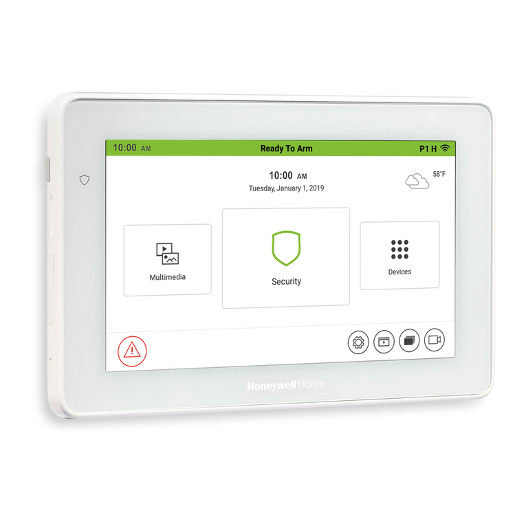
  9. Honeywell Home Touchscreen 6290W User manual

Honeywell Home Touchscreen 6290W User manual

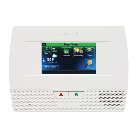
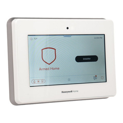
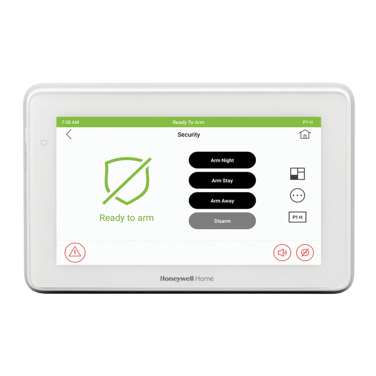
6290W Touchscreen Home Security System
Quick Installation Guide
Full Installation Guide [Part Number 800-24918] available online at:
https://mywebtech.honeywellhome.com
To reset the Touchscreen, press and hold the side Power Button for 3 seconds and then select the reset button on the screen to start the reset function. The Touchscreen
can also be reset by pressing and holding the reset button for approximately 15 seconds until the touchscreen resets automatically.
TOUCHSCREEN INITIALIZATION
When initially powered, the boot sequence and the "Set ECP Address" is displayed. If
using one Touchscreen, leave the address set to 1 and select Apply. If using more
than one, power-up each Touchscreen one at a time, and set each Touchscreen
address to one of the addresses enabled in the control panel.
Operation Mode Selection: Select Normal Mode, Safe Mode or Demo Mode
to turn
the option on or off.
SYSTEM INFORMATION / UPGRADES
To view the current software version installed, Interface name and MAC Address,
select Setup → System Information.
Software upgrades may be available. Log in to MyWebTech (see above) and enter
the model name in the “Search by” “My Product” field. Select Go; click on
Touchscreen software update SBS”.
ECP ADDRESS
If the screen is displaying “ECP Error”, the ECP address in the Touchscreen is not
valid for the panel that it is connected to. In this case, to change the ECP Address,
enter the default code of “4140” to advance to the next screen.
Note: Default code “4140” is the Touchscreen default installer code before connecting
to a control panel. Once connected to a control panel, use that panel’s installer code.
1. Select Setup →System Setup → CS Setup .
2. Enter an Authorized Code, if required.
3. Select ECP Address&Options ; enter an ECP Address. The available ECP
Addresses are:
1-2, 5-6…. for residential controls
1-2, 3-30... for commercial controls under Rev. 10; supports 3 AUIs. *See
Important Note below.
1-30 ……. for commercial controls Rev. 10 or higher; supports 6 AUIs.
*IMPORTANT NOTE: If multiple Touchscreens are being used, they must be set to
addresses 1, 2, and X (where X equals any address from 3 through 30). Only one
AUI type (Touchscreen) device may be assigned to an address from 3 through 30 on
commercial control panels.
4. Select the Homepage and Operation Mode from the Options menu.
DISPLAY & AUDIO SETUP
1. From the Home/Security screen select Setup , slide the Brightness / Volume
bar up or down to change settings.
2. Select Setup → Disp & Audio Setup ; enter an Authorized Code.
- To adjust the screen timeouts, select a time interval from the drop-down list for
each option (Backlight Off After, To Homepage After, and Auto Slideshow After.)
- Select Chime, Voice or Voice Chime operating mode.
- To clean the Touchscreen screen, select the Clean Screen icon; select
Continue, or select Cancel to exit.
- Changes are saved when you exit this screen.
USER SETUP
1. Select Setup → System Setup → USER .
2. Select and enter a User name and enter an Authorized Code for this user.
Select each field and enter the appropriate information.
3. Select to save the user information or select Back arrow to return to the
previous screen.
For available user numbers, see control panel instructions.
TIME & DATE
1. Select Setup → System Setup→ Time/Date Setup .
2. Enter an “Authorized Code”.
a) If Get Time is selected, the Touchscreen downloads the time/date from the
control panel and exits the “Set Time” screen. (The Get Time icon appears with
residential panels and may not appear with all commercial panels.)
b) Or, set the time/date from the Set Time/Date screen.
3. Select to save: A pop-up message displays “Time Setting Confirmation”,
select Yes or No.
MULTIMEDIA
NOTE: Micro SD card max size is 64GB and must be FAT32, SDXC format. Recommended is
Kingston or Samsung.
Picture Setup:Insert a media card (Micro SD/SDHC) with up to 1000 stored (jpg,
.bmp, .png or .jpeg) photos.
1. Select the Multimedia icon and then select the Picture folder to view.
2. Select a photo and select Play to view pictures in a slide show format.
3. To set a picture as wallpaper, select the Default/Wallpaper folder to activate the
wallpaper setting.
4. Select the Multimedia information icon to view picture/video information.
5. Select Back to return to the previous screen.
Video Setup: Insert a media card (Micro SD/SDHC) with stored (avi, .ts, .mpg, .mp4,
.mov, .mkv, or .flv) video files.
1. Select the Multimedia icon and then select the Video folder to view.
2. Select Play to start the selected video file.
3. Select the Multimedia information icon to view picture/video information.
4. Select Back to return to the previous screen.
SCREEN SECURITY
See the full Installation Guide for user Authority Levels.
1. Select Setup → System Setup → CS Setup .
2. Enter an Authorized Code; select Screen Security .
- To make changes, select the line to change and the level of user to have
access, and then slelct to save changes.
CODE AUTHORITY
1. Select Setup → System Setup → CS Setup.
2. Select Code Authority .
3. Enter the 4-digit Code for the user you want to obtain authority level information
about.
PANEL CONFIGURATION
1. Select Setup → System Setup → CS Setup.
2. Enter an Authorized Code and select Panel Config .
Select to clear the Touchscreen and reload the panel configuration into the
Touchscreen.
NIGHT SETUP
The NIGHT function can be set to arm the system in one of five arming modes. To
change the arming mode;
1. Select Setup →System Setup → Advanced Setup.
2. Enter an Authorized Code.
3. Select Night Setup; select desired mode:
Away - Stay - Instant (default) - Night (Residential Panel Only) – Maximum.
4. Select to save changes.
EMERGENCY MESSAGES
1. Select the PANIC Icon.
2. Select and hold (for at least 2 seconds) the associated alarm icon (FIRE, POLICE
or MEDICAL).
DISARMING THE SYSTEM AND SILENCING ALARMS
To silence Alarms or Trouble conditions: enter your 4-digit user code, select the
Clear button, then enter your 4-digit user code again.
To test the Alarm, select the Security and More Choices icons.
- Select Console Mode and refer to the Control Panel User Guide for
procedure.
U
L
Use a UL Listed, battery-backed supply for UL installations. The battery supplies
power to these keypads in case of AC power loss. The battery-backed power supply
should have enough power to supply the keypads with the UL required minimum
standby power time.
IMPORTANT: Touchscreens powered from supplies that do not have a backup
battery do not function if AC power is lost. Make sure to power at least one keypad
in each partition from the control’s auxiliary power output or UL Listed battery backed
up power supply.
Panel Faults –If Panel Fault icons are displayed on the Security screen, contact your alarm company. See the full Installation Guide.
AC Loss
Bell Failure
Expander Failure
Low Battery
LRR Supervision Failure
Max Attempts
Exceeded
Pager Failure
Telco-1 Cut
Telco-2 Cut
Wireless Failure
Panic
MOUNTING
OPERATING THE TOUCHSCREEN
For operating instructions, see the User Guide for the
control panel used with this Touchscreen.
This 6290W Touchscreen is for indoor use only and should be mounted at a comfortable viewing level. Avoid
mounting in areas of high condensation such as bathrooms or in locations where bright light or sunlight shines
directly on the screen. The Touchscreen is surface mounted directly to a wall.
Locate the mounting plate and attach to a wall using the 4 screws provided. Insert bottom side of Touchscreen
over the mounting plate and then click in top side to snap into place. Install the cover securing screw at the bottom
of the device to secure. The bottom securing screw must be installed.
To remove the Touchscreen from its mounting location, insert the end of a screwdriver between the plate and the
touchscreen and twist to loosen and pull out to remove.
WIRING
CONNECT WIRING
Route wiring from the controller through the opening in the
mounting plate.
Connect the Touchscreen in parallel with Touchscreens
and other peripheral devices using the Touchscreen data
(ECP) bus. If more than one Touchscreen is wired to one
run, then the maximum lengths must be divided by the
number of devices on the run. (e.g., the maximum length
is 75 feet if two devices are wired on a #22 gauge run).
Wire Gauge
Length
#22 gauge
150 feet
#20 gauge
240 feet
#18 gauge
350 feet
#16 gauge
550 feet
Refer to the control panel Installation Guide for additional
information.
SPECIFICATIONS
Mechanical Specifications:
Width: 7.91 inches (200.9mm)
Height: 5.04 inches (128.016mm)
Depth: .827 inches (21.00mm)
Electrical specification:
Backlight ON, Sound ON
12V, 270mA
Operating Environment:
Humidity: 93% RH, non-condensing
Operating Temp.
14°F to 131°F / -10°C to 55°C
(UL tested 32°-120°F / 0° to 49°C)
Ship/Storage/Temp.: 40°F to 158°F / -40°C to 70°C
Install in accordance with NFPA-70 and NFPA-72.
This equipment should be installed in accordance with
National Electrical Code, NFPA 70, Standard for the
Installation of Residential Fire Warning Systems,
CAN/ULC-S540 and Chapter 2 of the National Fire
Alarm Code, ANSI/NFPA 72 (National Fire Protection
Association, Batterymarch Park, Quincy, MA 02269).
Printed information describing proper installation,
operation, testing, maintenance, evacuation planning,
and repair service is to be provided with this equipment.
Warning: Owner’s instruction notice: ’Not to be
removed by anyone except occupant’
This system must be checked by a qualified technician
at least once every three (3) years.
Note: The product should not be disposed of with other
household waste. Check for the nearest authorized
collection centers or authorized recyclers. The correct
disposal of end-of-life equipment will help prevent
potential negative consequences for the environment
and human health.
Compatibility
The table below identifies the alarm systems that the
Touchscreen can interface with, the maximum number of
Touchscreens that can be used with each system, and the
minimum alarm panel software revision level for compatibility.
Panel Type Panel Version
Max # of
touchscreens
15p V3 and higher 2
20p V3 and higher 4
21ip V1 and higher 4
128BPT V10 and higher 6
250BPT V10 and higher 6
128FBPT V10 and higher 6
250FBPT V10 and higher 6
Warning: 5G Band 5150-5250 MHz is only for indoor use.
FEDERAL COMMUNICATIONS COMMISSION & ISED CANADA STATEMENTS
The user shall not make any changes or modifications to the equipment unless authorized by the Installation Instructions or User's Manual. Unauthorized changes or
modifications could void the user's authority to operate the equipment.
CLASS B DIGITAL DEVICE STATEMENT
This equipment has been tested to FCC requirements and has been found acceptable for use. The FCC requires the following statement for your information.
This equipment generates and uses radio frequency energy and if not installed and used properly, that is, in strict accordance with the manufacturer's instructions, may
cause interference to radio and television reception. It has been type tested and found to comply with the limits for a Class B computing device in accordance with the
specifications in Part 15 of FCC Rules, which are designed to provide reasonable protection against such interference in a residential installation. However, there is no
guarantee that interference will not occur in a particular installation. If this equipment does cause interference to radio or television reception, which can be determined
by turning the equipment off and on, the user is encouraged to try to correct the interference by one or more of the following measures:
• If using an indoor antenna, have a quality outdoor antenna installed.
• Reorient the receiving antenna until interference is reduced or eliminated.
• Move the radio or television receiver away from the receiver/control panel.
• Move the antenna leads away from any wire runs to the receiver/control panel.
• Plug the receiver/control panel into a different outlet so that it and the radio or television receiver are on different branch circuits.
• Consult the dealer or an experienced radio/TV technician for help.
ISED CLASS B STATEMENT
This Class B digital apparatus complies with Canadian ICES-003.
Cet appareil numérique de la classe B est conforme à la norme NMB-003 du Canada.
FCC / ISED STATEMENT
This device complies with Part 15 of the FCC Rules, and ISED’s license-exempt RSSs. Operation is subject to the following two conditions: (1) This device may not
cause harmful interference (2) This device must accept any interference received, including interference that may cause undesired operation.
Cet appareil est conforme à la partie 15 des règles de la FCC et exempt de licence RSS d’ISED. Son fonctionnement est soumis aux conditions suivantes: (1) Cet
appareil ne doit pas causer d' interférences nuisibles. (2) Cet appareil doit accepter toute interférence reçue y compris les interférences causant une réception
indésirable.
Responsible Party / Issuer of Supplier’s Declaration of Conformity: Honeywell International, 2 Corporate Center Dr., Melville, NY 11747, Ph: 516-577-2000.
Partie responsable / Émetteur de la déclaration de conformité du fournisseur : Honeywell International, 2 Corporate Center Drive., Melville, NY 11747, Tél. 516 577-2000
SUPPORT & WARRANTY
For the latest warranty information, please go to:
https://www.security.honeywellhome.com/hsc/resources/wa/index.html
For patent information, see https://www.resideo.com/patent
SUPPORT: For technical support, call 1-800-645-7492 M-F 8:30am to 5pm EST
REFER TO INSTALLATION INSTRUCTIONS FOR THE CONTROL PANEL WITH WHICH THIS DEVICE IS USED FOR
WARRANTY INFORMATION AND LIMITATIONS OF THE ENTIRE ALARM SYSTEM.
UL Notes: For residential burglar alarm applications, the entry delay time shall not exceed 15 seconds, therefore use is
restricted to compatible listed control units capable of being programmed for this time parameter.
Connect only keypads to: Aux. + / Aux. - and Data input / Data output.
Ê800-24916BsŠ
800-24916B 4/19 Rev B
2 Corporate Center Drive, Suite 100
P.O. Box 9040, Melville, NY 11747
© 2019 Resideo Technologies, Inc. Inc.
www.resideo.com/security
This product manufactured by Resideo and its
affiliates. The Honeywell Home Trademark is used under
license from Honeywell International Inc.

Other manuals for Touchscreen 6290W

5

Other Honeywell Home Security System manuals

Honeywell Home PROSiXFOB Assembly instructions

Honeywell Home

Honeywell Home PROSiXFOB Assembly instructions

Honeywell Home HS3SS Series User manual

Honeywell Home

Honeywell Home HS3SS Series User manual

Honeywell Home Ademco Vista-21iPLTE User manual

Honeywell Home

Honeywell Home Ademco Vista-21iPLTE User manual

Honeywell Home HS351X User manual

Honeywell Home

Honeywell Home HS351X User manual

Honeywell Home PROA7PLUS Series Assembly instructions

Honeywell Home

Honeywell Home PROA7PLUS Series Assembly instructions

Honeywell Home HS331 Series User manual

Honeywell Home

Honeywell Home HS331 Series User manual

Honeywell Home Water Defense RWD41 User manual

Honeywell Home

Honeywell Home Water Defense RWD41 User manual

Honeywell Home VISTA-21iP User manual

Honeywell Home

Honeywell Home VISTA-21iP User manual

Honeywell Home PROA7PLUS Series Instruction manual

Honeywell Home

Honeywell Home PROA7PLUS Series Instruction manual

Honeywell Home SMART HOME SECURITY User manual

Honeywell Home

Honeywell Home SMART HOME SECURITY User manual

Honeywell Home Touchscreen 6290W User manual

Honeywell Home

Honeywell Home Touchscreen 6290W User manual

Honeywell Home VISTA Series User manual

Honeywell Home

Honeywell Home VISTA Series User manual

Honeywell Home Touchscreen 6290W User manual

Honeywell Home

Honeywell Home Touchscreen 6290W User manual

Honeywell Home HS342X User manual

Honeywell Home

Honeywell Home HS342X User manual

Honeywell Home Ademco Vista Series User manual

Honeywell Home

Honeywell Home Ademco Vista Series User manual

Honeywell Home PROWLTOUCH Instruction manual

Honeywell Home

Honeywell Home PROWLTOUCH Instruction manual

Honeywell Home TUXEDOW User manual

Honeywell Home

Honeywell Home TUXEDOW User manual

Honeywell Home ADEMCO VISTA-15P User manual

Honeywell Home

Honeywell Home ADEMCO VISTA-15P User manual

Honeywell Home Touchscreen 6290W Owner's manual

Honeywell Home

Honeywell Home Touchscreen 6290W Owner's manual

Honeywell Home Touchscreen 6290W User manual

Honeywell Home

Honeywell Home Touchscreen 6290W User manual

Honeywell Home TUXEDOW User manual

Honeywell Home

Honeywell Home TUXEDOW User manual

Honeywell Home PROSiXSIREN User manual

Honeywell Home

Honeywell Home PROSiXSIREN User manual

Honeywell Home TUXEDOW User manual

Honeywell Home

Honeywell Home TUXEDOW User manual

Honeywell Home Ademco Vista-V21SIALTE Assembly instructions

Honeywell Home

Honeywell Home Ademco Vista-V21SIALTE Assembly instructions

Popular Security System manuals by other brands

Siemens IMKW6-10 Installation instruction

Siemens

Siemens IMKW6-10 Installation instruction

Pepperl+Fuchs NVD-111 manual

Pepperl+Fuchs

Pepperl+Fuchs NVD-111 manual

Unitronics Jazz Micro-OPLC JZ10-11-T17 installation guide

Unitronics

Unitronics Jazz Micro-OPLC JZ10-11-T17 installation guide

Intelbras AMT 4010 Smart installation guide

Intelbras

Intelbras AMT 4010 Smart installation guide

AFRISO WGA 01 manual

AFRISO

AFRISO WGA 01 manual

Innovative Technology ICU quick start guide

Innovative Technology

Innovative Technology ICU quick start guide

Risco WisDom user manual

Risco

Risco WisDom user manual

Pyronix Paragon Super User instructions

Pyronix

Pyronix Paragon Super User instructions

Ecco EB5200 Installation and operation instruction

Ecco

Ecco EB5200 Installation and operation instruction

Saferhomee HTZSAFE 806A user manual

Saferhomee

Saferhomee HTZSAFE 806A user manual

Honeywell ADEMCO VISTA SERIES Programming guide

Honeywell

Honeywell ADEMCO VISTA SERIES Programming guide

Raytec Vario W8 Installation and setup guide

Raytec

Raytec Vario W8 Installation and setup guide

X10 MS10A Set up and operating instructions

X10

X10 MS10A Set up and operating instructions

Ecco 6550 Installation and operation instruction

Ecco

Ecco 6550 Installation and operation instruction

Energeeks EG-CIPBAT001 Quick installation guide

Energeeks

Energeeks EG-CIPBAT001 Quick installation guide

Metra Electronics Spyclops PRO MTH1309 quick start guide

Metra Electronics

Metra Electronics Spyclops PRO MTH1309 quick start guide

Electronics Line EL-2626AC installation guide

Electronics Line

Electronics Line EL-2626AC installation guide

Trend Micro txOne networks EdgeIPS IPS-102-BP-TM Quick setup guide

Trend Micro

Trend Micro txOne networks EdgeIPS IPS-102-BP-TM Quick setup guide

manuals.online logo
manuals.online logoBrands
  • About & Mission
  • Contact us
  • Privacy Policy
  • Terms and Conditions

Copyright 2025 Manuals.Online. All Rights Reserved.