i
Table of Contents
Features and Installation Highlights...................................................................................................................... 1
Capabilities and Functions ................................................................................................................................... 1
Compatible Devices.............................................................................................................................................. 2
Important Installation Highlights (Installer Please Read) ..................................................................................... 2
Mounting and Wiring the Control........................................................................................................................... 3
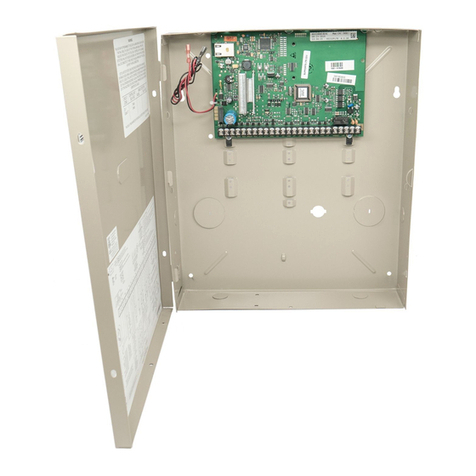
Installing the Control Cabinet and PC Board ....................................................................................................... 3
Cabinet and Lock ............................................................................................................................................ 3
Mounting the PC Board Alone (no RF Receiver)............................................................................................ 3
Mounting Board with RF Receiver .................................................................................................................. 3
AUXILIARY DEVICE CURRENT DRAW WORKSHEET................................................................................ 4
AC Power, Battery, and Ground Connections...................................................................................................... 5
1361-GT Transformer ..................................................................................................................................... 5
Battery Connections........................................................................................................................................ 5
Battery Saver Feature ..................................................................................................................................... 5
Earth Ground................................................................................................................................................... 5
Sounder (Bell) Connections ................................................................................................................................. 6
Basic Connections........................................................................................................................................... 6
Supervised Output .......................................................................................................................................... 6
Connecting the Keypads and Other Addressable Devices .................................................................................. 6
Connections .................................................................................................................................................... 6
Supplementary Power (optional)..................................................................................................................... 6
Keypad Notes.................................................................................................................................................. 7
Optional LTE-21V Module............................................................................................................................... 7
Table of Device Addresses .................................................................................................................................. 7
Hardwire Zones and Zone Expansion.................................................................................................................. 8
Hardwire Zones............................................................................................................................................... 8
Double-Balanced Zones.................................................................................................................................. 8
Zone Doubling................................................................................................................................................. 8
Smoke Detectors............................................................................................................................................. 9
Smoke Detector Notes .................................................................................................................................... 9
4219/4229 Expansion Zones .......................................................................................................................... 9
Installing the RF Receiver and Wireless Transmitter Zones.............................................................................. 10
Compatible Receivers ................................................................................................................................... 10
Receiver Connections ................................................................................................................................... 10
RF Receiver Notes........................................................................................................................................ 10
Installing the Transmitters ............................................................................................................................. 11
Transmitter Battery Life................................................................................................................................. 11
Installing a Keyswitch ......................................................................................................................................... 12
Keyswitch Connections ................................................................................................................................. 12
Keyswitch Notes............................................................................................................................................ 12
Connecting Relay Modules and Output Triggers ............................................................................................... 13
4204/4229 Relay Modules ............................................................................................................................ 13
On-Board Triggers......................................................................................................................................... 14
Audio Alarm Verification Connections........................................................................................................... 15
Internet (IP) Connection ................................................................................................................................ 17
LTE-21V Module Installation .............................................................................................................................. 17
General Information ...................................................................................................................................... 17
Mounting the Module..................................................................................................................................... 17
IP/Cell Status LEDs....................................................................................................................................... 19
Signal Quality ................................................................................................................................................ 19
Signal Quality and Status LEDs.................................................................................................................... 19
Signal Strength and Status LED locations – Status LED Functions Table ........................................................ 20
Inadequate Signal Strength;.......................................................................................................................... 20
Using Stand-Alone Communication Device .................................................................................................. 20
Programming Overview ........................................................................................................................................ 21
About Programming............................................................................................................................................ 21
Mechanics of Programming.........................................................................................................................................21
Data Field Programming Procedures.....................................................................................................................21
Interactive Mode Programming (∗56, *57, ∗58, ∗79, ∗80, ∗81, ∗82) ......................................................................22
Loading Factory Defaults/Initializing for Download ................................................................................................22
Exiting the Programming Mode..............................................................................................................................22
Zone Type Definitions..................................................................................................................................................22
