IHP MAGNIFLAMEOD24NE Quick start guide

For more information, visit IHP.us.com
VENTED GAS LOG APPLIANCE ACCESSORY
OWNER’S OPERATION AND INSTALLATION
MANUAL
WHEN USED AS AN OUTDOOR APPLIANCE
WHEN USED AS INDOOR VENTED APPLIANCE
MFEB MAGNIFLAME EMBER BED ACCESSORY
BURNER KIT (CAT. NO. F0253) FOR USE ONLY
WITH BURNER SYSTEM MODELS
MAGNIFLAMEOD24NE, MAGNIFLAMEOD24NM,
MAGNIFLAMEOD24PE, MAGNIFLAMEOD24PM,
MAGNIFLAMEOD30NE, MAGNIFLAMEOD30NM,
MAGNIFLAMEOD30PE, MAGNIFLAMEOD30PM,
MFBOD24MN, MFBOD24MP, MNF24ONE, MNF24ONM,
MNF24OPE, MNF24OPM, MNF30ONE, MNF30ONM,
MNF30OPE, MNF30OPM
WARNING: If the information in this manual is not followed exactly, a fire or explosion
may result causing property damage, personal injury or loss of life.
— Do not store or use gasoline or other flammable vapors and liquids in the vicinity of
this or any other appliance.
— WHAT TO DO IF YOU SMELL GAS
• Do not try to light any appliance.
• Do not touch any electrical switch; do not use any phone in your building.
• Immediately call your gas supplier from a neighbor’s phone. Follow the gas supplier’s
instructions.
• If you cannot reach your gas supplier, call the fire department.
— Installation and service must be performed by a qualified installer, service agency or the
gas supplier.
INSTALLER: Leave this manual with the appliance.
CONSUMER: Retain this manual for future reference.
WARNING: Improper installation, adjustment, alteration, service or maintenance can
causeinjuryorpropertydamage.Readtheinstallation,operatingandmaintenanceinstruc-
tions thoroughly before installing or servicing this equipment.
WARNING: No not store gasoline or other flamable vapors and liquids in the vicinity of
this or any other appliance.An LP-cylinder not connected for use shall not be stored in the
vicinity of this or any other appliance.
WARNING: For Outdoor Use Only.
DANGER
IF YOU SMELL GAS:
1. Shut off gas to appliance.
2. Extinguish any open flame.
3. If odor continues, keep away from the
appliance and immediately call your gas
supplier or fire department.
TheMFEBaccessorykitmayonlybeusedwheninstalled
in a wood burning fireplace and may only be used with
the burner systems and log models listed in this manual.
CARBON MONOXIDE
WARNING
• This appliance can pro-
duce carbon monoxide
which has no odor.
• Using it in an enclosed
space can kill you.
• Never use this appli-
ance in an enclosed
space such as a camp-
er, tent, car or home.
DANGER
P/N 126913-01 REV. A 04/2017
fire-parts.com

IHP.us.com 126913-01A
2
SAFETY
DANGER:Carbonmonoxidepoisoningmay
lead to death!
Carbon Monoxide Poisoning: Early signs of carbon mon-
oxide poisoning resemble the flu, with headaches, dizziness
or nausea. If you have these signs, the fireplace may not be
working properly. Get fresh air at once! Have fireplace ser-
viced. Some people are more affected by carbon monoxide
than others. These include pregnant women, people with
heart or lung disease or anemia, those under the influence
of alcohol and those at high altitudes.
Natural and Propane/LP
gases are odorless. An odor-making
agent is added to these gases. The odor helps you detect a
gas leak. However, the odor added to the gas can fade. Gas
may be present even though no odor exists.
Make certain you read and understand all warnings. Keep
this manual for reference. It is your guide to safe and proper
operation of this fireplace.
WARNING: Any change to this appliance
or its controls can be dangerous.
Solid fuels shall not be burned in a fireplace
where a decorative appliance is installed.
Duetohightemperatures,theapplianceshould
belocatedoutoftrafficandawayfromfurniture
and draperies.
Donotplaceclothingorotherflammablemate-
rial on or near the appliance. Never place any
objects on the appliance.
Appliance base assembly becomes very hot
when running appliance. Keep children and
adults away from hot surface to avoid burns
or clothing ignition.Appliance will remain hot
foratimeaftershutdown.Allowsurfacetocool
before touching.
Carefully supervise young children when they
are in the room with appliance. When using
thehand-heldremoteaccessory,keepselector
switch in the OFF position to prevent children
from turning on burners with remote.
WARNING: Improper installation, adjust-
ment, alteration, service or maintenance
can cause injury or property damage. Refer
to this manual for correct installation and
operational procedures. For assistance or
additional information consult a qualified
installer, service agency or the gas supplier.
WARNING:Thisapplianceisforinstallation
only in a solid-fuel burning masonry or UL127
factory-built fireplace or in a listed unvented
vent free outdoor fireplace. Do not install this
appliance in an unvented fireplace indoors.
WARNING: Fireplace must be operated
only with doors fully open.
WARNING: This product contains and/or
generates chemicals known to the state of
California to cause cancer or birth defects or
other reproductive harm.
IMPORTANT: Read this owner’s manual care-
fullyandcompletelybeforetryingtoassemble,
operateorservicethisfireplace.Improperuse
of this fireplace can cause serious injury or
death from burns, fire, explosion, electrical
shock and carbon monoxide poisoning.
IMPORTANT:Whenspecificationsarelistedin
both this instruction manual and the burner
system's instruction manual, use the speci-
fications and/or requirements stated in this
instruction manual.
TABLE OF CONTENTS
Safety ..................................................................................2
Local Codes.........................................................................4
Unpacking............................................................................4
Product Features.................................................................4
Installation ...........................................................................4
Operation.............................................................................9
Specifications ......................................................................9
Technical Service.................................................................9
Replacement Parts..............................................................9
Troubleshooting.................................................................10
Parts..................................................................................11
Warranty.............................................................Back Cover
fire-parts.com

IHP.us.com
126913-01A 3
SAFETY
Continued
1. Thisapplianceisonlyfor usewith thetype ofgasindicated
onthe ratingplate.Thisappliance isnot convertiblefor use
with other gases.
2. Do not place propane/LP supply tank(s) inside any struc-
ture.Locate propane/LPsupplytank(s) outdoors(propane/
LP units only).
3. If you smell gas
•shut off gas supply
•do not try to light any appliance
•do not touch any electrical switch; do not use any phone
in your building
•immediately call your gas supplier from a neighbor’s
phone. Follow the gas supplier’s instructions
•if you cannot reach your gas supplier, call the fire depart-
ment
4. This appliance shall not be installed in a bedroom or bath-
room, unless installed as a vented appliance. See burner
system instruction manual for damper clamp installation.
This gas log set may not be installed as a vented appli-
ance in a bedroom or bathroom in the Commonwealth of
Massachusetts.
5. Before installing in a solid fuel burning fireplace, the chim-
ney flue and firebox must be cleaned of soot, creosote,
ashes and loose paint by a qualified chimney cleaner.
Creosote will ignite if highly heated. A dirty chimney flue
may create and distribute soot within the house. Inspect
chimney flue for damage. If damaged, repair flue and
firebox before operating appliance.
6. If fireplace has glass doors, never operate this appliance
withglass doorsclosed.If youoperateappliancewithdoors
closed, heat buildup inside fireplace will cause glass to
burst. Make sure there are no obstructions across open-
ings of fireplace.
7. To prevent the creation of soot, follow the instructions pro-
vided with your burner system's manual under Cleaning
and Maintenance.
8. Before using furniture polish, wax, carpet cleaner or similar
products, turn appliance off. If heated, the vapors from these
products may create a white powder residue within burner
box or on adjacent walls and furniture.
9. Do not use this appliance as a wood burning appliance.
Useonlythe logsprovided withtheappliance. Donot burn
solid fuels in this appliance.
10.Do not run appliance
•where flammable liquids or vapors are used or stored
•under dusty conditions
You must operate this appliance with the fire-
place screen and hood in place. Make sure
fireplace screen and hood are in place before
running appliance.
Keep the appliance area clear and free from
combustible materials, gasoline and other
flammable vapors and liquids.
11.Do not use this appliance to cook food or burn paper or
other objects.
12.Do not use this appliance if any part has been exposed to
or under water. Immediately call a qualified service tech-
nician to inspect the room appliance and to replace any
part of the control system and any gas control which has
been under water.
13.Do not operate appliance if any log is broken.
14.Turn appliance off and let cool before servicing, installing
or repairing. Only a qualified service person should install,
service or repair appliance.
15.This appliances must not be connected to any external
electrical source.
16.Operating appliance above elevations of 4,500 feet may
cause pilot outage.
17.To prevent performance problems, do not use propane/
LP fuel tank of less than 100 lb. capacity (propane/LP
units only).
18.Provide adequate clearances around air openings.
19.Do not operate fireplace if any log is broken.
If used with MFEB accessory ember burner,
this appliance shall only be installed in a wood
burning fireplace.
fire-parts.com

IHP.us.com 126913-01A
4
LOCAL CODES
Install and use appliance with care. Follow all local codes.
In the absence of local codes, use the latest edition of The
National Fuel Gas Code, ANSI Z223.1/NFPA 54*.
*Available from:
American National Standards Institute, Inc.
25 West 43rd Street, 4th floor
New York, NY 10036
National Fire Protection Association, Inc.
1 Batterymarch Park
Quincy, MA 02169-7471
INSTALLATION
CAUTION: Do not remove the data plates attached
to the burner pan. The data plates contain important
warranty and safety information.
CAUTION: Before attempting to install this acces-
sory, read both the burner system instruction manual
and this instruction manual completely.
WARNING: Before installing in a solid fuel burning
fireplace,thechimneyflueandfireboxmustbecleaned
of soot, creosote, ashes and loose paint by a qualified
chimney cleaner. Creosote will ignite if highly heated.
A dirty chimney flue may create and distribute soot
within the house. Inspect chimney flue for damage. If
damaged, repair flue before operating heater.
NOTICE: Installation, service, and repair of this appli-
ancemustbeperformedbyaqualifiedinstaller,service
agency, company or gas supplier experienced with
this type of gas appliance. Only factory authorized
components listed in these instructions may be used
in accordance with the manufacturer’s instructions
and all codes and requirements of the authority hav-
ing jurisdiction. Any modifications to this kit, or use
of unauthorized components or accessory items will
void the manufacturer’s warranty, and may result in a
hazardous condition.
FLUE OPENING SPECIFICATIONS
Note: This vented appliance must be installed only in a solid-
fuel burning fireplace with a working flue and constructed of
noncombustible material.
Thecharts inFigure1,indicatetechnical informationregarding
the installation of your gas log set. Please make sure that all
of the specifications shown are applicable before installation
is attempted.
The fireplace must include a working flue and venting system
with the minimum openings shown in the Figure 1.
INSTALLATION AND CLEARANCES
WARNING:Maintaintheminimumclearances.Ifyou
can, provide greater clearances from floor, ceiling and
adjoining wall.
WARNING: Follow the fireplace and mantel clear-
ancerequirementsasshowninthefireplaceinstruction
manual.
MINIMUM FIREPLACE CLEARANCE TO COMBUSTIBLE
MATERIALS
Side Wall 16", Ceiling 42"
Floor 5", Front: 36"
UNPACKING
CAUTION: Do not remove the data plates
from the grate assembly. The data plates con-
tainimportantwarrantyandsafetyinformation.
1. Remove appliance base assembly from carton(s).
2. Remove all protective packaging applied to logs and ap-
pliance for shipment.
3. Check appliance for any shipping damage. If appliance is
damagedcall FMIPRODUCTS,LLC at1-866-328-4537for
replacement parts before returning to dealer.
PRODUCT FEATURES
OPERATION
This accessory is for use only with the models listed on the
front cover. When used with these models, the appliance
may only be installed in a site built wood burning fireplace or
a UL 127 listed wood burning fireplace. The fireplace's vent
damper must be locked in the open position. This accessory
may be used either indoors or outdoors.
COMMONWEALTH OF MASSACHUSETTS REQUIRE-
MENTS
These appliances are approved for installation in the US
state of Massachusetts if the following additional require-
ments are met:
•Un-ventedRoom Heatersshall be installedin accordance
with 527 CMR 30.
• Installation and repair must be done by a plumber or gas
fitter licensed in the Commonwealth of Massachusetts.
• The flexible gas line connector used shall not exceed 36
inches (92 centimeters) in length.
• The individual manual shut-off must be a T-handle type
valve.
• Unvented appliances may NOT be installed in bedrooms
or bathrooms.
• A working smoke detector must be installed in the area
where vent-free appliances are installed.
Sellerofunvented propaneor naturalgas-fired supplemen-
tal room heaters shall provide to each purchaser a copy of
527 CMR 30 upon sale of the unit.
fire-parts.com

IHP.us.com
126913-01A 5
INSTALLATION
Continued
Figure 1 - Technical Information Chart
Area of Various Standard Round Flues
Diameter Area
5" 20 sq. inches
6" 29 sq. inches
7" 39 sq. inches
8" 51 sq. inches
Chimney Height Minimum Permanent Flue Opening
6' to 15' 45 sq. inches
15' to 30' 29 sq. inches
FUEL INLET PRESSURE
SPECIFICATIONS (W.C.)
Min. Max.
NG 5.5" 10.5"
LP 11" 13"
LOG SIZING REQUIREMENTS WITH MFEB INSTALLED
Log
Size
Minimum Firebox Size
Height Depth Front
Width Rear*
Width
42" 29" 22" 39" 26.75"
48" 29" 22" 47" 33"
BURNER ORIFICE
NATURAL PROPANE/LP
IN. COLOR IN. COLOR
0.101 Green 0.065 Brass
VENTING SPECIFICATIONS FOR INSTALLATION
Thefireplace chimneyflue andvent mustbedraftingproperly.
To check the vent for proper drafting: Light a tightly rolled
newspaper on one end and place it at the inside front edge
of the fireplace. Observe the smoke and be sure the vent is
properlydrawingit upthechimney. If thesmoke spills outinto
the room, extinguish the flame and remove any obstruction
until proper venting is achieved.
The chimney flue must remain open as shown in the chart
above at all times during the operation of this log set.
For Massachusetts Residents Only
Installationofthis ventedgas log setin theCommonwealthof
Massachusettsrequires thedamper bepermanently removed
or welded in the fully open position.
INSTALLING DAMPER CLAMP
Secure the damper stop clamp provided to the leading edge
of the damper as shown in Figure 2. If for any reason this
clamp doesn't work on your fireplace, another suitable clamp
or permanent stop must be installed, or the damper blade
must be cut or removed.
Figure 2 - Attaching Damper Clamp
Damper
Damper
Clamp
Damper
Damper
Clamp
Damper
Manufactured Fireplace
Masonry Fireplace
INSTALLING MFEB TO BURNER ASSEMBLY
Installation items needed
- MFEB Ember Burner accessory
- 5/8'' wrench
- 5/16'' nut driver
- Phillips screwdriver
- Adjustable wrench
- Large pliers or pipe wrench
1. Attach MFEB burner pan to burner system using four (4)
#10 screws as shown in Figure 3.
Figure 3 - Attaching Burner Pan to Burner System
2. Locate the brass burner inlet fitting - orifice assembly.
It is shipped from the factory set for use on propane/LP
gas. Check the gas type for your installation to verify the
gas type, If the burner system is for propane/LP gas, no
changes are needed for this assembly, if the burner is
for natural gas, the outer orifice (stamped ''52'') must be
removed, (see Figure 4, page 6).
Holes for attching burner
pan to Burner System
Burner Pan
fire-parts.com

IHP.us.com 126913-01A
6
Figure 4 - Installing Brass Burner Inlet Fitting
Figure 5 - Installing Orifice Assembly to Burner Pan
Figure 6 - Attaching Burner Clamp to burner Pan
Figure 7 - Attaching Inlet Fitting, Orifice and Elbow
Figure 8 - Removing Cap From Tee
Figure 9 - Attaching stainless steel Flex Line
INSTALLATION
Continued
Orifice
Brass Burner
Inlet Fitting
3. Using thread sealant (resistant to action of propane/LP
gas) on larger end of the burner inlet fitting - orifice as-
sembly, screw the assembly through the hole in the left
side of the burner pan and into the burner as shown in
Figure 5. Tighten using a wrench.
4. Using burner clamp, screw and nut provided, assemble
the clamp to the pan and tighten. This will hold the burner
in place, (see Figure 6).
5. Using thread sealant (resistant to action of propane/LP
gas) on the exposed end of the burner inlet fitting - orifice
assemblyandonthethreaded endof theblack ironstreet
elbow, screw the adapter, elbow, and assembly together
as shown in Figure 7. The adapter must be positioned as
shown in figure. Tighten with wrench.
6. Remove cap from tee as shown in Figure 8.
7. Attach the stainless steel flex line to the tee and to the
adapter as shown in Figure 7 and Figure 9. Be certain to
place the compression nuts and ferrules on each end of
the flex line as shown. Tighten the nuts using a wrench.
Brass Burner
Inlet Fitting
Burner Clamp Burner Pan
Nut
Screw
Burner Tube
Burner Pan
Thread
sealant
Black Iron
Street Elbow
Burner Inlet
Fitting
Adapter
Nut and Ferrule
(Don't tighten until step 7)
Tee Connector
Cap
Ferrule
Tee Connector
Stainless Steel
Flex Line
Cap
fire-parts.com

IHP.us.com
126913-01A 7
IMPORTANT:Installequipment shutoff valvein anaccessible
location.The equipmentshutoffvalve isfor turningonor shut-
ting off the gas to the appliance.
Check your building codes for any special requirements for
locating equipment shutoff valve to fireplaces.
Apply pipe joint sealant lightly to male NPT threads. This will
prevent excess sealant from going into pipe. Excess sealant
in pipe could result in clogged appliance valves.
WARNING: Use pipe joint sealant that is
resistant to liquid petroleum (LP) gas.
Figure 10 - External Regulator With Vent Pointing Down
Propane/LP
Supply Tank External
Regulator
with Vent
Pointing
Down
INSTALLATION
Continued
CONNECTING TO GAS SUPPLY
WARNING:Aqualifiedservicepersonmust
connect appliance to gas supply. Follow all
local codes.
CAUTION: Never connect propane/LP fire-
place directly to the propane/LP supply. This
appliance requires an external regulator (not
supplied). Install the external regulator be-
tween the appliance and propane/LP supply.
WARNING:Neverconnectnaturalgasfire-
place to private (non-utility) gas wells. This
gas is commonly known as wellhead gas.
Installation Items Needed
Before installing appliance, make sure you have the items
listed below.
• external regulator (supplied by installer)
• piping (check local codes)
• sealant (resistant to propane/LP gas)
• equipment shutoff valve *
• test gauge connection *
• sediment trap
• tee joint
• pipe wrench
• approved flexible gas line with gas connector (if allowed by
local codes) (not provided)
* An equipment shutoff valve with 1/8" NPT tap is an ac-
ceptable alternative to test gauge connection. Purchase the
optional equipment shutoff valve from your dealer.
For propane/LP units, the installer must supply an external
regulator. The external regulator will reduce incoming gas
pressure.Youmust reduceincoming gaspressure tobetween
11" and 14" of water. If you do not reduce incoming gas pres-
sure,appliance regulatordamagecouldoccur. Installexternal
regulator with the vent pointing down as shown in Figure 10.
Pointing the vent down protects it from freezing rain or sleet.
CAUTION: Use only new, black iron or
steel pipe. Internally-tinned copper tubing
may be used in certain areas. Check your
local codes. Use pipe of 1/2" diameter or
greater to allow proper gas volume to appli-
ance.Ifpipeistoosmall,unduelossofvolume
will occur.
Installation must include an equipment shutoff valve, union
and plugged 1/8" NPT tap. Locate NPT tap within reach for
test gauge hook up. NPT tap must be upstream from appli-
ance (see Figure 11).
* Purchase the optional equipment shutoff valve from your
dealer.
**Minimum inlet pressure for purpose of input adjustment.
Figure 11 - Gas Connection
Pipe Cap Tee
Nipple Joint
Gas Control
3" Minimum
Sediment Trap
Equipment Shutoff Valve
With 1/8" NPT Tap*
Approved Flexible
Gas Hose (if allowed
by local codes)
PROPANE/LP
From External
Regulator
(11" W.C.**
to 14" W.C.
Pressure)
NATURAL
From Gas
Meter
(5" W.C.**
to 10.5"
W.C.
Pressure)
fire-parts.com

IHP.us.com 126913-01A
8
INSTALLATION
Continued
We recommend that you install a sediment trap in supply line
asshown inFigure11,page7. Locatesedimenttrap whereitis
withinreach forcleaning.Installinpiping systembetween fuel
supply and appliance. Locate sediment trap where trapped
matter is not likely to freeze. A sediment trap traps moisture
andcontaminants.Thiskeeps themfrom goinginto appliance
controls. If sediment trap is not installed or is installed wrong,
appliance may not run properly.
CAUTION: Avoid damage to gas control.
Hold gas control with wrench when connect-
ing it to gas piping and/or fittings.
CHECKING GAS CONNECTIONS
WARNING: Test all gas piping and connec-
tions, internal and external to unit, for leaks
after installing or servicing. Correct all leaks
at once.
WARNING: Never use an open flame to
check for a leak. Apply a noncorrosive leak
detection fluid to all joints. Bubbles forming
show a leak. Correct all leaks at once.
CAUTION:Makesureexternalregulatorhas
beeninstalledbetweenpropane/LPsupplyand
appliance. See guidelines under Connecting
to Gas Supply, page 7.
PRESSURE TESTING GAS SUPPLY PIPING SYSTEM
Test Pressures In Excess Of 1/2 PSIG (3.5 kPa)
1. Disconnect appliance with its appliance main gas valve
(controlvalve) andequipmentshutoffvalve fromgassupply
pipingsystem. Pressuresin excessof 1/2psig willdamage
appliance regulator.
2. Cap off open end of gas pipe where equipment shutoff
valve was connected.
3. Pressurize supply piping system by either opening pro-
pane/LP supply tank valve for propane/LPgas or opening
main gas valve located on or near gas meter for natural
gas or using compressed air.
4. Check all joints of gas supply piping system. Apply noncor-
rosiveleak detectionfluidtoall joints.Bubblesformingshow
a leak.
5. Correct all leaks at once.
6. Reconnect appliance and equipment shutoff valve to gas
supply. Check reconnected fittings for leaks.
Test Pressures Equal To or Less Than 1/2 PSIG (3.5 kPa)
1. Close equipment shutoff valve (see Figure 12).
2. Pressurize supply piping system by either opening pro-
pane/LP supply tank valve for propane/LPgas or opening
main gas valve located on or near gas meter for natural
gas or using compressed air.
3. Checkalljoints fromgasmeter toequipmentshutoff valve
fornaturalgas or propane/LPsupply to equipmentshutoff
valve for propane/LP (see Figure 13 or Figure 14). Ap-
ply noncorrosive leak detection fluid to all joints. Bubbles
forming show a leak.
4. Correct all leaks at once.
Figure 12 - Equipment Shutoff Valve
Open
Closed
Equipment
Shutoff
Valve
Figure 13- Checking Gas Joints (Propane/LP Only)
Control Valve
Location
Propane/LP
Supply Tank Equipment
Shutoff Valve
Figure 14 - Checking Gas Joints (Natural Gas Only)
Gas Meter
Control Valve
Location
Equipment Shutoff Valve
fire-parts.com

IHP.us.com
126913-01A 9
INSTALLATION
Continued
PRESSURE TESTING APPLIANCE GAS
CONNECTIONS
1.
Open equipment shutoff valve (see Figure 12, page 8).
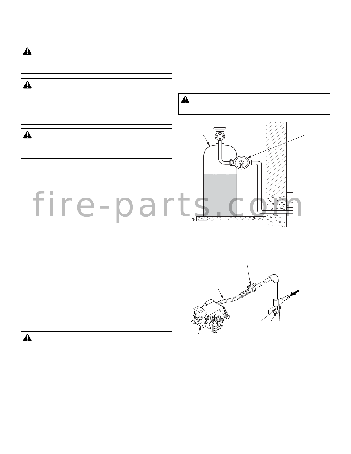
2. Open main gas valve located on or near gas meter for
natural gas or open propane/LP supply tank valve.
3. Makesure controlknobofapplianceis inthe OFFposition.
4. Check all joints from gas meter to equipment shutoff valve
for natural gas or propane/LP supply to equipment shutoff
valve for propane/LP (see Figure 13, or Figure 14, page 8).
Applynoncorrosive leakdetection fluid toall joints. Bubbles
forming show a leak.
5. Correct all leaks at once.
6. Light appliance (follow the Operation instructions accom-
panyingyour burnersystem). Checkall otherinternal joints
for leaks.
7.
Turnoffappliance(seeTo Turn OffGas toAppliance,
follow
the instructions accompanying your burner system
).
ADDING PAN MATERIAL
Two pan materials are included with the MFEB. Lava rock,
small grey/black rock is for use on the burner pan for outdoor
applications. Vermiculite, light tan - lightweight material, is
for use on the burner pan for indoor applications.
Apply the material for your application on the burner pan by
spreading it evenly across the burner pan so that it is level
with the edges of the burner pan and covers the round, tu-
bular burner.
ADDING EMBER MATERIAL (INDOORS ONLY)
Two ember materials are included with the MFEB. Apply
rock wool glowing embers by spreading a 1/2 inch layer of
rock wool on top of the pan material. Pull any clumps apart
so that the flames will pass through the pieces. Apply Plati-
num Bright Embers by placing the pieces randomly over the
rock wool.
WARNING: Failure to position the parts in
accordance with these diagrams or failure to
use only parts specifically approved with this
appliance may result in property damage or
personal injury.
OPERATION
CAUTION: Follow the OPERATION instruc-
tions accompanying your burner system for
criticalsafetyinformationandforinstructions
on how to operate your burner system.
SPECIFICATIONS
MAGNIFLAMEOD24PE, MAGNIFLAMEOD24PM,
MAGNIFLAMEOD30PE, MAGNIFLAMEOD30PM,
MFBOD24MP, MNF24OPE, MNF24OPM,
MNF30OPE, MNF30OPM
Burner systems with MFEB optional ember burner installed.
• Rating (Variable): 50,000/70,000 Btu/Hr
• Type Gas: Propane/LP
• Manifold Pressure: 10.0" W.C.
• Inlet Gas Pressure (in. of water):
Max - 14" W.C., Min* - 11" W.C.
*For purpose of input adjustment
MAGNIFLAMEOD24NE, MAGNIFLAMEOD24NM,
MAGNIFLAMEOD30NE, MAGNIFLAMEOD30NM,
MFBOD24MN, MNF24ONE, MNF24ONM,
MNF30ONE, MNF30ONM,
Burner systems with MFEB optional ember burner installed.
• Rating (Variable): 40,000/65,000 Btu/Hr
• Type Gas: Natural
• Manifold Pressure: 3.4" W.C.
• Inlet Gas Pressure (in. of water):
Max - 10.5" W.C., Min* - 5" W.C.
*For purpose of input adjustment
REPLACEMENT PARTS
Normally, all parts should be ordered through your IHP distributor
or dealer. Parts will be shipped at prevailing prices at time of order.
NEVER USE SUBSTITUTE MATERIALS. USE OF NON-APPROVED PARTS
CAN RESULT IN POOR PERFORMANCE AND SAFETY HAZARDS.
When ordering repair parts, always give the following information:
1. The model number of the appliance.
2. The serial number of the appliance.
3. The part number.
4. The description of the part.
5. The quantity required.
6. The installation date of the appliance.
If you encounter any problems or have any questions concerning the
installation or application of this appliance, please contact your dealer.
TECHNICAL SERVICE
You may have further questions about installation, operation, or
troubleshooting. Please contact your IHP dealer for any ques-
tions or concerns. When contacting your dealer please have
your model and serial numbers of your appliance ready. You
can also visit our web site at IHP.us.com.
fire-parts.com

IHP.us.com 126913-01A
10
MFEB TROUBLESHOOTING
WARNING: Turn off log set and let cool before servicing. Only a qualified service person should service and
repair log set.
Note: All troubleshooting items are listed in order of operation.
Note: Also see troubleshooting section of your burner system's instruction manual.
POSSIBLE CAUSE
1.Poor fuel quality
2.Fireplace venting system not draft-
ing properly
3.Improper fuel/air mixture
4.Excessive gas supply/pressure
1.Passage of air/gas across irregular
surfaces
1.Incorrect gas supply or pressure
2.Blocked burner orifice or burner
manifold ports
3.Improper burner orifice size
REMEDY
1.Contact localnatural orpropane/LP
gas company
2.Adjust damper wide open and/or
have fireplace and venting profes-
sionally cleaned and checked
3.Remove any foreign items from the
flamepatternand/orcheckforproper
orifice sizing
4.Preheat flue in very cold weather
1.Relieve any tight bends or kinks in
gas supply line
1.Check for proper gas supply pres-
sure
2.Free burner orifice and manifold
ports of any burrs, paint, or other
blockage
3.Verifyproperburnerorificesizing(see
Figure 1, page 5)
OBSERVED PROBLEM
Log set is smoking/sooting exces-
sively
(Note: It is natural and unavoidable
for vented gas log sets to produce
moderate levels of carbon (soot)
whereflamescontactthelogs.Thisis
especially true with propane/LPgas.)
Burner is excessively noisy
(Note:Themovementandcombustion
of gas will create low, unavoidable
levels of noise.)
Burner flame is too low or too high
WARNING: If you smell gas
• Shut off gas supply.
• Do not try to light any appliance.
• Do not touch any electrical switch; do not use any phone in your building.
• Immediatelycallyourgassupplierfromaneighbor’sphone.Followthe gassupplier’sinstruc-
tions.
• If you cannot reach your gas supplier, call the fire department.
IMPORTANT: Operating appliance where impurities in air exist may create odors. Cleaning supplies, paint, paint remover,
cigarette smoke, cements and glues, new carpet or textiles, etc., create fumes. These fumes may mix with combustion air
and create odors. These odors will disappear over time.
fire-parts.com

IHP.us.com
126913-01A 11
PARTS
MFEB
1
4
13
6
12
7
11
10
8
9
3
2
5
This list contains replaceable parts used in your appliance. When ordering parts, follow the instructions listed under Replace-
ment Parts on page 11 of this manual.
KEY
NO. PART NO. DESCRIPTION QTY.
1 J8157 Burner Outdoor Ember Bed 1
2 J8158 Pan Outdoor Ember Bed 1
3 J7231 Nut #8-32 1
4 J8159 Clamp, 1'' Burner 1
5 J6489 Plate, Log Placement 1
6 J8160 Decal, Installation 1
J8161 Decal, Pan Material 1
7 J8162 Decal, Warning 1
8 J7230 Screw, PPH #8-32 X .38 1
9 J7202 Injector, (NG) 1
10 J7221 Holder, Injector (NG) 1
11 J8163 Orifice (0.101) 1
12 J8164 Elbow 3/8'' Pipe Street 1
13 J8165 Adapter, 3/8 Pipe to 3/8 Tube 1
PARTS AVAILABLE, NOT SHOWN - ALL MODELS
J7274 Vermiculite, Pln. Bag #1.00 1
J7275 Pan Material - 0.4# Pln. Bag Ember 1
J7287 Clamp Damper 1
J7096 Lava Rock Bag Assembly 4.5 Lbs. 1
J4714 Flex Tube 1
J4733 Compression Nut and Ferrule 2
This list contains replaceable parts used in your appliance. When ordering parts, follow the instructions listed under Replace-
ment Parts on page 11 of this manual.
fire-parts.com

IHP reserves the right to make changes at any time, without notice, in design,
materials, specifications, prices and also to discontinue colors, styles and
products. Consult your local distributor for fireplace code information.
Printed in U.S.A. © 2010 Innovative Hearth Products
P/N 126913-01 Rev. A 04/2017 1508 Elm Hill Pike, Suite 108 • Nashville, TN 37210
fire-parts.com
This manual suits for next models
17
Table of contents
Other IHP Fireplace Accessories manuals
Popular Fireplace Accessories manuals by other brands

Nordpeis
Nordpeis N-29U installation manual

Hauck
Hauck Fireplace Guard Instructions for use

Valor
Valor LEGEND G3 763BPB installation instructions

SBI
SBI AC01323 manual

American Hearth
American Hearth ALS3236FFD-1 Installation instructions and owner's manual

pleasant hearth
pleasant hearth 885A quick start guide

Lennox
Lennox TRAD-FPK-BG-LG installation instructions

pleasant hearth
pleasant hearth WS104L instructions

Dimplex
Dimplex SOP-495-AL install guide

My Fireplace Blower
My Fireplace Blower BLOT240 installation instructions

Napoleon
Napoleon GD862KT installation instructions

Valor
Valor H3 Series installation manual