manuals.online logo
Brands
  1. Home
  2. •
  3. Brands
  4. •
  5. IHP
  6. •
  7. Fireplace Accessories
  8. •
  9. IHP STK-LIN60-B KIT User manual

IHP STK-LIN60-B KIT User manual

NOTE: DIAGRAMS & ILLUSTRATIONS ARE NOT TO SCALE. 1
STK-LIN60-B KIT
INSTALLATION INSTRUCTIONS FOR STK-LIN60-B KIT
[FOR USE IN ALLUMEDLX60TEN-B, ALLUME60TEN-B, DRL4060TEN-B, AND DRL6060TEN-B FIREPLACES]
HEARTH PRODUCTS
KITS AND ACCESSORIES
P/N 901058-00 REV. NC 07/2020
WARNING
This kit must be installed by a qualified installer,
service agency, or gas supplier at the time of the
fireplace installation. These instructions must
be used in conjunction with the installation and
operation manual provided with the fireplace.
IMPORTANT NOTICE
STK-LIN60-B KIT IS REQUIRED FOR UPGRADING FIREPLACE
TO A SEE-THRU APPLICATION.
IMPORTANT NOTICE
BLOWER USE IS NOT COMPATIBLE WITH THE STK-LIN60-B
KIT.
GENERAL INFORMATION
The STK-LIN60-B KIT is designed to upgrade the fireplace to a
see-thru application.
When Installing this kit, reference the framing dimensions for the
see-thru application and follow the framing instructions shown on
the fireplace installation Instructions. Follow all other installation
requirements for the fireplace as detailed in the installation manual.
IMPORTANT! CONVERT THE FIREPLACE TO A SEE-THRU
APPLICATION BEFORE INSTALLING INTO THE FRAMING.
REFER TO INSTALLATION INSTRUCTIONS AND CARE AND OPERA-
TIONS MANUAL (IICO)FOR FRAMING DETAILS BEFORE INSTALLING
THIS KIT.
ALL WARNINGS AND PRECAUTIONS IN THE INSTALLATION AND
OPERATION MANUAL PROVIDED WITH THE FIREPLACE APPLY TO
THESE INSTRUCTIONS.
Kit Components
2 ea. Nailing Flange side
2 ea. Tile Stop L/R
2 ea. Tile Stop Top/Bottom
2 ea. Sight Obstructor
1 ea. Standoff Heatshield
1 ea. Door Access Cover
1 ea. Fireboard Assembly
1 ea. Glass Door
1 ea. Rear Standoff Assembly
1 ea. Barrier
22 ea. #10 Hex Head Screw
15 ea. #8 Phillips Head Screw
36 ea. Bugle drywall Screws
TOOLS REQUIRED (not included)
Electric Drill/Driver Gun
Phillips Screwdriver Bits
5/16 Nut Driver
5/16” Wrench
INSTALLER: Leave this manual with the appliance
CONSUMER: Retain this manual for future reference
Fireboard
Assembly
Nailing
Flange L/R
Tile Stops
L/R
Tile Stops
Top/Bottom
Door Access
Cover
Glass
Door
Barrier
STK-LIN60-B KIT
Cat. No. Model Number Description
F4410 STK-LIN60-B KIT Kit, Linear 60 See-Thru
Table 1 See Figure 1
Figure 1 - STK-LIN60-B KIT
Sight Obstructors
Standoff
Heatshield
Rear Standoff
Assembly
NOTE: DIAGRAMS & ILLUSTRATIONS ARE NOT TO SCALE.
2
ALLUMEDLX60TEN-B and DRL6060TEN-B model only, disconnect
blower assembly power cord from the fireplace control module
harness. Discard blower assembly and blower harness as blowers
are not compatible on a see-thru application.
Preparing Fireplace for See-Thru Application
1. Install rear standoff assembly, as shown in Figure 2, using eight
(8) of the #10 hex head screws.
2. Install the standoff heatshield, using three (3) #10 hex head screws
(two in the lower front, and one going upward into the standoff
assembly). See Figure 2.
3. Remove the rear heatshield assembly by removing the 12 hex head
screws fastening it to the back of the fireplace. This assembly will
not be reused and can be discarded (see Figure 2).
Figure 2
Figure 3
Figure 4
Rear Standoff
Assembly
Rear Heatshield
Assembly
Standoff
Heatshield
False Door
4. Remove the ten (10) hex screws fastening the false door to the
fireplace. Lift upward and outward to remove false door. Remove
any gasket material that may have been left behind on the firebox
door mating surface. This part will not be reused and can be
discarded (see Figure 3).
5. Place the bottom edge of the door assembly into the door channel
on the firebox. The tabs on the bottom of the door on each side
will fall into corresponding slots on the door channel of the firebox
(see Figure 4).
6. While holding the door closed, place one of the sight obstructors
against the door as shown. With both the door and sight obstructor
in place, fasten them to the firebox together using five (5) #10
hex head screws(see Figure 4).
Door Assembly
Bottom Door Edge,
Tab and Channel
Sight
Obstructor
7. Attach the remaining sight obstructor to the upper heatshield as
shown using five (5) #10 hex head screws (see Figure 5).
NOTE: DIAGRAMS & ILLUSTRATIONS ARE NOT TO SCALE. 3
Figure 5
Upper Heatshield
Sight Obstructor
8. Partially install two (2) #8 Phillips head screws into the upper
left and right tile stop mounting holes. Partially loosen (DO NOT
REMOVE) the two (2) lower outside tile stop Phillips head screws.
Hang the top and bottom tile stops on those outside screws and
install the remaining three (3) #8 Phillips head screws on each
tile stop (see Figure 6).
9. Using six (6) #8 Phillips head screws,install the side tile stops
as shown in Figure 6.
10. Bend both side door access cover supports upward until they
are flat. Bend the center door access cover toward the door on
the fireplace (see Figures 6 and 7).
11. Install the door access cover onto the door access cover supports,
inserting tabs on cover into the slots on the cover support shown
in Figure 7.
12. Install the barrier by sliding it upward into the top barrier channel,
then push back slightly on the bottom, and lower it into the lower
barrier channel (see Figure 7).
Door Access
Cover
Slot
Upper and Lower
Barrier Channels
Barrier Screen
Door Access
Cover
Door Access
Cover Support
Figure 7
Figure 6
Partially Loosen,
Both Sides
Do Not Remove Partially Install
Both Sides
Door Access
Cover Supports
NOTE: DIAGRAMS & ILLUSTRATIONS ARE NOT TO SCALE.
4
Figure 8
Nailing
Flange
Mounting
Screws
13. Proceed with installation of the fireplace into the framing per
instructions in the Installation and Operation Manual provided
with the fireplace.
14. Once the fireplace is installed in the framing, install the nailing
flanges. Loosen (DO NOT REMOVE) the three (3) hex head
mountingscrewsonbothsidesofthefireplace showninFigure
8. Slide the nailing flange onto those screws on both sides,
with the bottom most slot going onto the bottom most screw.
Once in place, using a 5/16” wrench, tighten the mounting
screws through the access holes in the nailing flange (see
Figure 8, Page 4).
NOTE: DIAGRAMS & ILLUSTRATIONS ARE NOT TO SCALE.
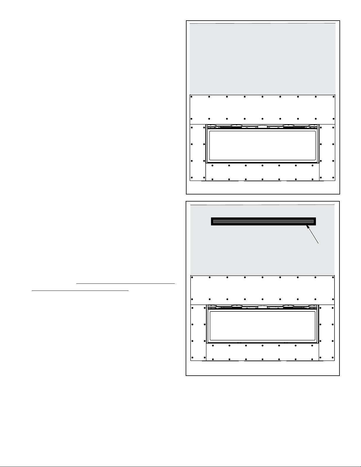
Figure 8 - Flush Wall Installation Without HeatFlo Kit
Figure 9 - Flush Wall Installation with HeatFlo Kit Installed
Fireplace
Fireplace
HeatFlo Trim
in Place
5
FINISHING FIREPLACE
The appliance is designed to mate with 1/2” wall sheathing materials
such as drywall, plywood, wood composites, or non-combustible
materials.
Finishing and Sealing Joints
All joints between the finished wall sheathing and the appliance
must be sealed with non-combustible materials. Sealants, such
as caulk or mastic used to seal the gap between the wall and the
fireplace, should be rated at a minimum continuous exposure to
300 ºF.
Finishing Around Opening with Gypsum Wallboard
Gypsum wallboard (drywall) joints adjacent to the fireplace opening,
including the non-combustible board on the appliance, require
special attention to minimize cracking. When installing gypsum
wallboard around the fireplace, install the hole for the fireplace
opening in a single wallboard sheet, if possible. This will minimize
the joints adjacent to the fireplace opening.
Tape wall board joints around the fireplace opening with fiberglass-
mesh tape. It will provide a more crack-resistant joint than paper
tape. Fill, smooth and finish wall joints with chemically setting-type
joint compound. It will provide a more crack-resistant joint than
air-drying light-weight compound.
NOTE: NEVER install combustible material (wall finish, surround,
trim, etc.) on, in front of, or overlapping any part of the fireplace
front face.
NOTE: Non-combustible fireboard is provided with the fireplace.
DO NOT SUBSTITUTE.
Installing Fireboard
1. Using 1” self drill bugle drywall screws (supplied), install non-
combustible fireboard at bottom, sides and top of fireplace
face (See Figure 8).
2. Apply 1/2” wall sheathing materials such as drywall, plywood,
wood composites, or non-combustible materials to the rest
of the wall. NOTE: When applying drywall, minimize number
of joints to reduce potential for cracking.
NOTE: Factory supplied tile stops protrude 3/4" from unit and
will allow installation of standard tile and thin set on top of the
noncombustible fireboard.
NOTE: The HeatFlo Register Trim ships from the factory painted
black and it may be painted another color to match the wall color.
Use high temperature paint with a minimum 400°F continuous rating
(Figure 9). Do not finish over any of the opening in the trim outlet.
6
Innovative Hearth Products (IHP) reserves the right to make changes at any
time, without notice, in design, materials, specifications, prices and also
to discontinue colors, styles and products. Consult your local distributor for
fireplace code information.
Printed in U.S.A. © 2020 Innovative Hearth Products
P/N 901058-00 REV. NC 07/2020 1769 East Lawrence Street • Russellville, AL 35654

This manual suits for next models

1

Other IHP Fireplace Accessories manuals

IHP EPIC-TRIM-B User manual

IHP

IHP EPIC-TRIM-B User manual

IHP PCBE-325 User manual

IHP

IHP PCBE-325 User manual

IHP Envy AKC-CLS-DLSCNV User manual

IHP

IHP Envy AKC-CLS-DLSCNV User manual

IHP Montebello Series User manual

IHP

IHP Montebello Series User manual

IHP AK4 User manual

IHP

IHP AK4 User manual

IHP OAK-UVFRC User manual

IHP

IHP OAK-UVFRC User manual

IHP CHAROAK35 User manual

IHP

IHP CHAROAK35 User manual

IHP SV4.5HTKCT User manual

IHP

IHP SV4.5HTKCT User manual

IHP 900077-07 User manual

IHP

IHP 900077-07 User manual

IHP Superior 900347-00 User manual

IHP

IHP Superior 900347-00 User manual

IHP FBK-LIN User manual

IHP

IHP FBK-LIN User manual

IHP SG-01 User manual

IHP

IHP SG-01 User manual

IHP RDV-CONTF-BLK User manual

IHP

IHP RDV-CONTF-BLK User manual

IHP BWBK User manual

IHP

IHP BWBK User manual

IHP MERIT ZEN GARDEN MLDVTCD-35 User manual

IHP

IHP MERIT ZEN GARDEN MLDVTCD-35 User manual

IHP DEL SOL User manual

IHP

IHP DEL SOL User manual

IHP F2624 User manual

IHP

IHP F2624 User manual

IHP MAGNIFLAMEOD24NE Quick start guide

IHP

IHP MAGNIFLAMEOD24NE Quick start guide

IHP SV4.5-TWSK User manual

IHP

IHP SV4.5-TWSK User manual

IHP UZY-7-B User manual

IHP

IHP UZY-7-B User manual

IHP CDFBBK-35 User manual

IHP

IHP CDFBBK-35 User manual

IHP BLB36SF Series User manual

IHP

IHP BLB36SF Series User manual

IHP Snap-Pak User manual

IHP

IHP Snap-Pak User manual

IHP BVCBK User manual

IHP

IHP BVCBK User manual

Popular Fireplace Accessories manuals by other brands

Nordpeis N-29U installation manual

Nordpeis

Nordpeis N-29U installation manual

Regency Fireplace Products Masport 410 905 Owners & installation manual

Regency Fireplace Products

Regency Fireplace Products Masport 410 905 Owners & installation manual

Valor L3 installation manual

Valor

Valor L3 installation manual

FireplaceXtrordinair 4237 Installation

FireplaceXtrordinair

FireplaceXtrordinair 4237 Installation

Style selections LOG RACK WITH STORAGE SHELF 15261L Assembly instructions

Style selections

Style selections LOG RACK WITH STORAGE SHELF 15261L Assembly instructions

Valor GV60NTK Installation & operation instructions

Valor

Valor GV60NTK Installation & operation instructions

Wonderfire Gasflame 3 owner's guide

Wonderfire

Wonderfire Gasflame 3 owner's guide

BuckMaster EMBER VISION 100 SERIES manual

BuckMaster

BuckMaster EMBER VISION 100 SERIES manual

Ashley ASHFSMK-W Assembly and installation

Ashley

Ashley ASHFSMK-W Assembly and installation

Valor G4 790FTV installation manual

Valor

Valor G4 790FTV installation manual

Jøtul 520 Series Installation and operating instructions

Jøtul

Jøtul 520 Series Installation and operating instructions

Valor Legend G4 Series installation manual

Valor

Valor Legend G4 Series installation manual

HPC MLFPK Series Installation & operation instructions

HPC

HPC MLFPK Series Installation & operation instructions

ShelterLogic 90490 instructions

ShelterLogic

ShelterLogic 90490 instructions

FireplaceXtrordinair 864 TRV (Top/Rear Vent) manual

FireplaceXtrordinair

FireplaceXtrordinair 864 TRV (Top/Rear Vent) manual

Valor 975 installation instructions

Valor

Valor 975 installation instructions

Napoleon B52NG-1 Installation and operation manual

Napoleon

Napoleon B52NG-1 Installation and operation manual

Dimplex SOP-285-GB install guide

Dimplex

Dimplex SOP-285-GB install guide

manuals.online logo
manuals.online logoBrands
  • About & Mission
  • Contact us
  • Privacy Policy
  • Terms and Conditions

Copyright 2025 Manuals.Online. All Rights Reserved.