IMER COMBI 250 V Guide

COMBI
250
V
SAWINGMACHINE
cgp. 1188trg9
$lN 403189
207'-a
:,(eNae
A'.,enue
Sc San Fran:rsco,
CA f.i080
Tel 650
- 872
- 22aC
Fax 553 - 87Jr
- 5-i32
OPERATI
NG,
MAI
NTENANCE,
SPARE
PARTS
MANUAL
IMER u.s.A.
tnc.
207,Lawrence
Avenue
SouthSan
Francisco.
California94080IMEREAST
ZZ WestnamptonPlace
Capitol
Heights,
MD
20743
Tel 301
-336
- 3700
Fax301
- 336
- 6681
612002-R1
-Cod.3210213
-
(6s0)
872-2200

@TMESH;;#
rnc.
Dear
Customer,
Congratulations
on your choice of purchase:
IMER saws are
the resultof years of experience
and are equipped
with all the
latest
technical
innovations.
[- woaKNG tN sAFEry.
Towork
in complete
safety,
read
the
following
instructions
carefully
before
usingthe
machine.
Towork
in complete
safety,
read
the
following
instructions
carefully
before
usingthe
machine.
This
OPERATION
AND
MATNTENANCE
manuatmust
be
kepton
site
bythe
person
in
charge,
e.g.
the
SITEFOREMAN,
and
must
aiways
be avaiiabie
for
consuiiaiion.
The
manual
is
tobe
considered
integralpart
ofthe
machine
and
must
bekept
for
future
reference
untilthe
machine
is
disposed
of.lfthe
manual
is
damaged
or
lost,
areplacement
maybe requested
from
themanufacturer.
The
manual
contains
important
information
regarding
site
preparation,
machine
use,
maintenance
procedures,
and
requests
forspare
parts.
Nevertheless,
the
installer
and
the
operator
must
bothhave
adequate
experience
and
knowledge
ofthe
machine
prior
to
USE.
To guarantee
complete
safety
oftheoperator,
safeoperation
and
long
life
ofequipment,
follow
theinstructions
inthis
manual
carefully,
and
observe
all
safety
standards
currenily
in
force
for the prevention
of accidents
at work(use
of safety
footwear
and
suitable
clothing,
helmets,
gloves,
goggles
etc.).
A Make sure that
alt signs are legible.
/!\ - It is strictly forbidden to carry out any form of
modification to the steel structure o7 workin! parts of
tltemachine.
IMER
INTERNATIONAL
declines
altresponsibility
for
failure
to
coinply
with
laws
and
standardsgoverning
the
useof this
equipment,
in particular,
improper
use,
cjefective
power
supply,
lack
ofmaintenance,
unautho:-ised
modifications,
and
partiat
ortotal
failure
to
observe
the
instructions
contained
in
this
manual.
IMER
INTERNATIONAL
reserves
the
right
to
modifyfeatures
of
the
saw
and
contents
ofthis
manual,
without
the
obligation
to
update
previous
machines
andlor
manuals.
1. TECHNICAL
DATA
ffid intable
1
and
electrical
specifications
intable
2.
Feature 115/60
Hz
Power (kW
)11
Rated voltage(V) 115
Frequency
(Hz) 60
Absorbed current 14.4
Number
of
poles 2
rpm 3400
Service type s6 40%
Insulation
category F
Protection
category tP55
Capacitor
(pF) 110(o
50xl
20)
2. DESIGN
STANDARDS
Thesaws
have
beendesigned
andmanufactured
according
tothe
foflowing
europeanstandards:EN292-1-2;
EN60204-
1:EN
12418.
3. NOISE
EMISSIONLEVEL
Table
3specifiesthesound
emissionlevelsmeasured
onthe
saw(Lwa) inaccordancewith
ENISO 3744andthe
sound
pressure
level
measuredat the
earof theoperator
under
no
lload
conditions
(\o) .
TABI.E3
SAATTI3MICHI€ T\PEOFI\4OTCR \o \^
OM25OV AETRC 70 85
4. GENERAL
SAW DESCRIPTION
4.
I General description:
The Combi 250 V is a saw comprisingthe following
main sub-
groups :
- cutting
head (ref.
A fig.1).
- sliding
guide (ref.
B fi9.1).
- water collectiontank (ref.
C fi9.1).
- frame (ref.
D fiq.2).
- cutting surface (ref. F fig.2).
- stand (ref.G fig.s).
The cutting
head is mountedon a reinforced
aluminium
profile
and is equipped
with horizontal
and verticalmovement
facilities.The
aluminium
profile
is hinged
onto sheetsteelarms
(ref.H
fig.5) and the entireunitcan rotatethrough
a5" ( fig.6)
by means of the relative
handwheels
(ref.Lfig, 7).
The cutting
surfaces
are positioned
on the tubularframe of the
saw which is placed on the tank constructedin impact-
resistant
plastic.
The waterimmersion
pump is mountedbelow the cutting
surfaceson a specialbracket and supplies a water distributor
inside
the blade
guardfor cooling
the cutting
bladeduring
operation.
The high resistance
plastic
handle(ref.M
fig. 6), is equipped
with the main ON-OFF switch on the ooerator
side to facilitate
saw activationand shutdown.Theraised oositionof the red
OFF buttonon the handle is designed
to facilitate
shutdown of
the machinein the eventof an emergency.
The motor
capacitoris locatedin a protected
position
insidetlre handle.
The saw is fittedwith a guard to guarantee
optimalsafety
during
operationand to protect
the user during cutting
cycles.
A valveis mounted above the blade
guard to adjust the flow
rateof water deliveredto the cuttino
blade.
4.2 Processable
materials:
This saw has been designed for cutting the following
materials:
ceramictiles,
masonry and stone in general
with
TECHNICAL DATA
- Tabte
1
Model coMBt
250v
Max. diamond blade diameter 10inches
Diamond blade hole diameter 1 inches
Singlephase
motor
(11SV
60Hz)
output 1.1
Kw
Max.
blade rotation
speed (115V
60Hz) 3.400rpm
Worktop dimensions 500x840
mm
90' cut length
(th=16mm) 660mm
Lengtlr of cuts from above 785mm
Maximum
cut depth
with single
s
tro
ke 66mm
Maximum cut depth with two strokes 95mm
Water pump flow rate 10
L/nriir
Water tank capacity 42L
Machine dimehsions 1
040x560x640mm
Packed machine dimensions 1050x570x660mm
Ww

@IMERU.;#
rnc.
maximum
dimensions
compatible
with
thelength,
cutting
depth
anddimensions
of thesurfaces
specified
inTable
1.
Maximum
weight
ofprocessable
materials:
25
kg.
4.3 Unsuitable
materiat:
Materials
unsuitable
forthis
machine
areall
those
not
specified
inparagraph
4.2.
ln any event,
before
usingthesawwith
materiats
otherthan
as specified
by themanufacturer
forthissawmodel,
contact
IMERINTERNATIONAL
S.o.A.
4\i - IJse
of this machine with workpiece.s
oufside the
specified dimensions is strictty prohibited and constitutes
a hazard for the operator.
5. APERATIONSAFETY
Ai Before,using the saw, ensure
that att protection
devices are fitted.
/!\l - Neveruse fhe sawin environments
subject to the
risk of explosions, fire or underground.
Thesaw is notfitted
withspecific
lighting
andtherefore
the
workplace
mustbe sufficiently
litfor this
purpose.
The
power
lines
must
belaid
to
prevent
any
possible
damage.
Never
standthe
sawon the
power
supplycable.
Ensure
that
theelectrical
connection
is protected
against
the
riskof waterpenetration
in connectors.
Useexclusively
connectors
and couplings
equipped
withwater
spray
protection.
- Never
useinadequate
or makeshift
electricallines
or cables
without
earthing;
if in doubt
consult
a specialisedtechnician.
- Repairs
to theelectrical
circuit
must
beperformed
exclusively
by specialised
personnel.
Disconnect
the
machine
fromthe power
supply
before
performing
maintenance
or
repairs.
6.GENERAL
SAFEry WARNINGS
Note
that
this
machine
has
been
designed
toensure
optimai
performance
andmaximum
safety:however
theoperator
must
also
guarantee
this
level
of safetyby paying
specialattention
tothe
machine
throughout
allwork
phases.
It, Ensure that an efficient earthing sysfem rs
installed.
2. Work only with all protection devices fitted
correctly and in efficient working order.
J. Keep the machine clean: general cleaning
(and the work surfaces in particutar) represents an
important safety factor.
4. Always stop the machine and disconnect from
the power supply before cleaning or removing any
protection device (for maintenance or drsassembly
purposes).
lf water jets are used for cleaning, never point jets
directly at the power supply unit or electric motor.
5. Remove rings, watches, bracelefs or ties before
using the machine,' fhese elements constitute a serjous
ttazard to the operator.
A/so ensure that s/eeyes are tight around the wrists,
hair is tied back and robust footwear is used.
6. Never cut workpieces that have dimensions or
weiglrt that are not suited to machine i capacity as
specified by the manufacturer (see point 4.2)
7. Always use personal protection devices such
as safety goggles, suitably sized g/oves, ear muffs or
plugs and hair caps when necessary.
B. Use original diamond blades as recommended
by the manufacturer to ensure optimal pertormance of
the machine-
9. Always keep hands well away from the working
zone while the machine is running; before removing
workpieces from the blade area, always press fhe stop
pushbutton to shut down rotation.
10. The instrucfions in this manual are aimed at
machine users (operators, maintenance engineerfl-
11. Never use diamond blades that are chipped.
or
deformed.
12. Never use blades over the rotation speed
specified by the manufacturer.
13. Use exclusively water-cooled continuous rim
blades suited to the material to be cut.
14. Never dry cut material or cut when cooling
water levels are low.
15. Ensure that the machine, with or without stand,
is placed on a stable surface with a maximum
inclination of 5".
7. SAFEW DEVICES
Tffi been
constructed
taking
intoaccount
current
harmonisedEuropeansafetystandards.
Accordingto machine
directive9B/37lEECallsafetydevices
have
been
installedwiththeaimofsafeguardingthe
operator.
7.1Guards and safety devices
Themachine
is equipped
withfixed
guards,
securedby
meansof screwsand protections
thatprevent
access
to
movingor dangerous
parts.
All fixed
guards,
covers,shields
fixedby meansof screws
havebeen
envisaged
to protect
theoperator
(maintenance
engineers,
techniciansand others)frorn
possible
accidents
causeby electricaldischargeor movingmechanical
parts.
Therefoi'e
useof the machinewith
guards
removedor
modifiedin anyway is sti'ictly
prohibited.
A g"tore performing maintenance
or repairs to the
machine,
turn it off via ihe main switch and disconnect
from the power supply to prevent inadvertent start-up
and isolateall machine electricalcircuits.
8. MACHINE INSTALLATION
8.1 Lifting and handling
TheCombi250V sawweights
39Kg andcanbemovedby
meansofthe
sidehandlesonthetank
(ref.N
fig.s).
A aW"ys empty the tank beforemoving the machine.
8.2 POSITIONING.
Themachine
mustbeplaced
ona smoothsurfacethatis at
least
aslarge
asthetank,withthe
sawontherelativestand.
A - Ensurethat the standis positioned
on the relative
inserfs on the tank base and thus secured.
Thecorrectsidefortheoperatoris as shown
in Fig.3
position
Inthe
eventof moving
thesaw,
take
caretosecurethehead
bymeans
of thefixing
knobs
(ref.O,
L fig.7)andcarrythe
machine
bymeansofthe
handles
onthetank
(ref.N
fi9.5)
afterdisconnectingthepower
supply.
1l\ atways remove the ptug from the mains
power before
moving the machine.
8.3SIAT{DASSEMALY
@-assembled. Before
usecomplete
assemblyby inserting
thefoot
(ref.T
fi9.5)
in the
stand
frame
andtighteningthe
screwandnut
(ref.U
ng.5).

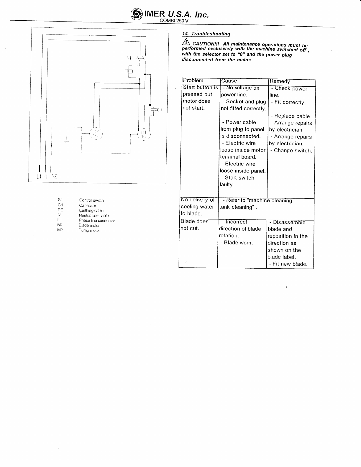
9. ELECTRICAL CONt:tECTtON
A .Ensure that vottage
da
ta
p
I
a
te s
p
ec
ifi
c
ations.-
Connect the machine to an efficient earthing system.
The size of the power cable wires must be based on
operating current and length of the power line to prevent
excessive voltage drops (ref.Table
4).
Combi250V-Tab.4
Cable length (m) v115
l= 14.4
Ao+12 13+20 21 32
Cable (mm,) 1.5 2.5 4
/r\
1
: \ Ensure that the electric line hasa suitabte
differential overtoad switch(RCD)(GFCI-USA).
Connect
the
sawplug
tothe
mains
.
- The saw is now ready
foroperation.
11.SAW START-IJP
connect
the
mains
power
cable
tothe
plug
on
the
electrical
panel.
Then
start
the
saw by means
of the
switch
on thehandle
(ref
.
P fig.6), comprising
two buttons:
green
forstart,red for
stop.
The switch
is fitted
with.low
voltage
protection:
in theevent
of accidentalpowerfailure,
press
thegreen
button
again
to
resume
operation.
In
the
event
of an emergency,press
thered
pushbutton
to
shut
down
the
machine
and
disconnect
the
plug
fromthe
power
mains.
TH
ERMAL
CUTOUT
PROTECTION:
A The electric motor
is protected against overload
by a thermal cutout; in the-
event of olerheating this
device shufs down the motor.
Cool the motor and restartby means the main switch
cn the handle (ref.P tig. 6).
12 . MACH'NE USE
Operation
The
correct
sidefortheoperator
isshowninfig.
3 ref
X.
Fill
thewater
tank
tothe
maximum
level
(approx.
42litres).
Connect
the
machine
tothe
power
mains
and
startas
described
in
paragraph
11.
Open
the valve
(ref.V
fig.7)
andensuresufficient
flow
of
cooling
water
tothe
diamond
blade.
qqtlils
Place the material to be cut on the cuttingsurface against the
fence at the required angle using a protractor.
Adjust the height of the cutting head by means of the
handwheel
(ref.
R fig. 6).
Ensure that the handwheels for angled cuts (ref. L fig. 7)
and tightened
fullydown.
Start
the saw as described
in paragraph
1
1.
Proceed with cutting moving the saw head by means of the
handle.
In the event of blade rotation
shutdown due to excessive
force, free the disk by moving it forwards and wait for the
saw to reach normal operating speed before resuming
operation.
AlsEq_sle
Loosen the handwheels (ref.Lfig. 7), set the cutting head at
the required angle, retighten
the handwheels, and proceed
as described
in the point
above.
Ensure
that
thd tank is kept
full
duringallwork phases
and in
the event of prolonged work intervals replace water
regularly and remove all processing residue.
Press the workpiece by hand onto the cutting surface.
Apply sufficient pressure on the handle to move the cutting
head without blocking the blade.
13 . Maintenance
13.1Premise
Routine maintenance operations can also be performed by
non-specialisedpersonnel provided that all safety standards
specified in the relative sections of this manual are observed
at
alltimes.
13.2
Machine
clean
The
machine
shouldbe cleanedexclusively
when
it is
siationary.
/\
l\ - All p.ower swifches must be sef fo "0" and plugs
must be disconnected from the mains.
r Never use compressed air; this could cause infiltration of
dust or residue in enclosed parts.
r Ensure that the cooling water nozzles are not obstructeo.
rAbove all the cooling water in the tank must be changed
every day.
r Recommended product for cleaning and lubricating
the
mechanical parts of the saw: WD40
13.3 Waste disposal
As regards disposal of processing waste observe all current
legislation
in the country of use.
13.4
Repairs
Repairs to the electrical installation must be performed
exclusively by specialised personnel. Use exclusively
original IMER spare parts; modifications to parts are strictly
prohibited.
The special design of the COMBI 250 V ensures
ihat no other maintenance cther than as specified
above is
required.
Ensure that the contacts of the power plug and plug-switch
assembly are efficient.lf oxidation is detected, clean
immediately
13,5 Cleaning the tank
Clean the tank in the event of build-up
of sedimenton the
base, or at least once a day. Failureto clean the tank could
impair
operationof the immersion pump used for circulation
of the diamond blade coolinq water. :
13.6
Blade
replacement
The
diamondbladeismade of material
thatmay be damaged
vrhensubject to high temperatures, and therefore must be
cooled during the work phases.
To replace the blade, proceed as follows:
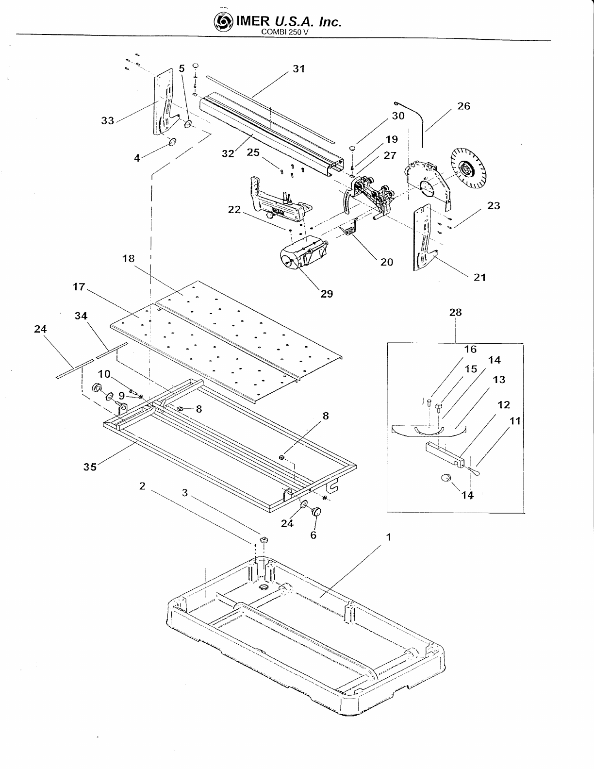
l.Block axial movement of the cutting head by means of the
handwheels(ref.
O fig. 7).
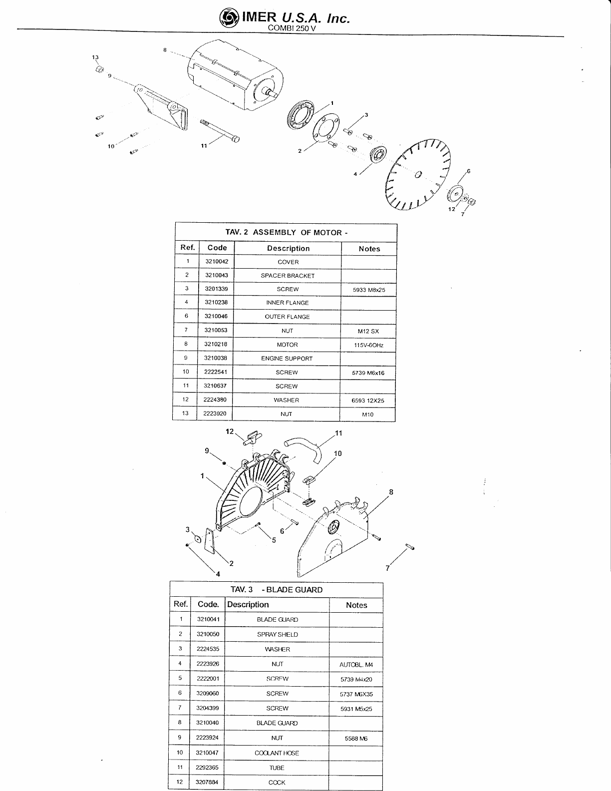
2. Disassemble the front guard (ref.D fig-a).
3. Loosen the locknut by rotating clockwise (leftthread),
using
a 19 mm wrench.
4. Move the cutting head forward slightly
and inclineto
remove the blade from its seat.
5 - Ensure that there are no foreign objects between the
fixingflange
and diamondblade.During
disassembly,
avoid
use of tools that could dent or deform the flange.
6 . Insert the new blade proceeding in reverse order of the
operationdescribed at point 4. Take specialcare to ensure
correct direction of rotation of the diamond blade.
7. Tighten
the bladelocknut
fullydown by rotating
anticlockwise(left thread), to a torque of 40 Nm.
13.7
Cleaningthe cooling
water supplvcircuit
At regular intervals (or when the flow rate of the blade
cooling water is reduced) clean the cooling water supply
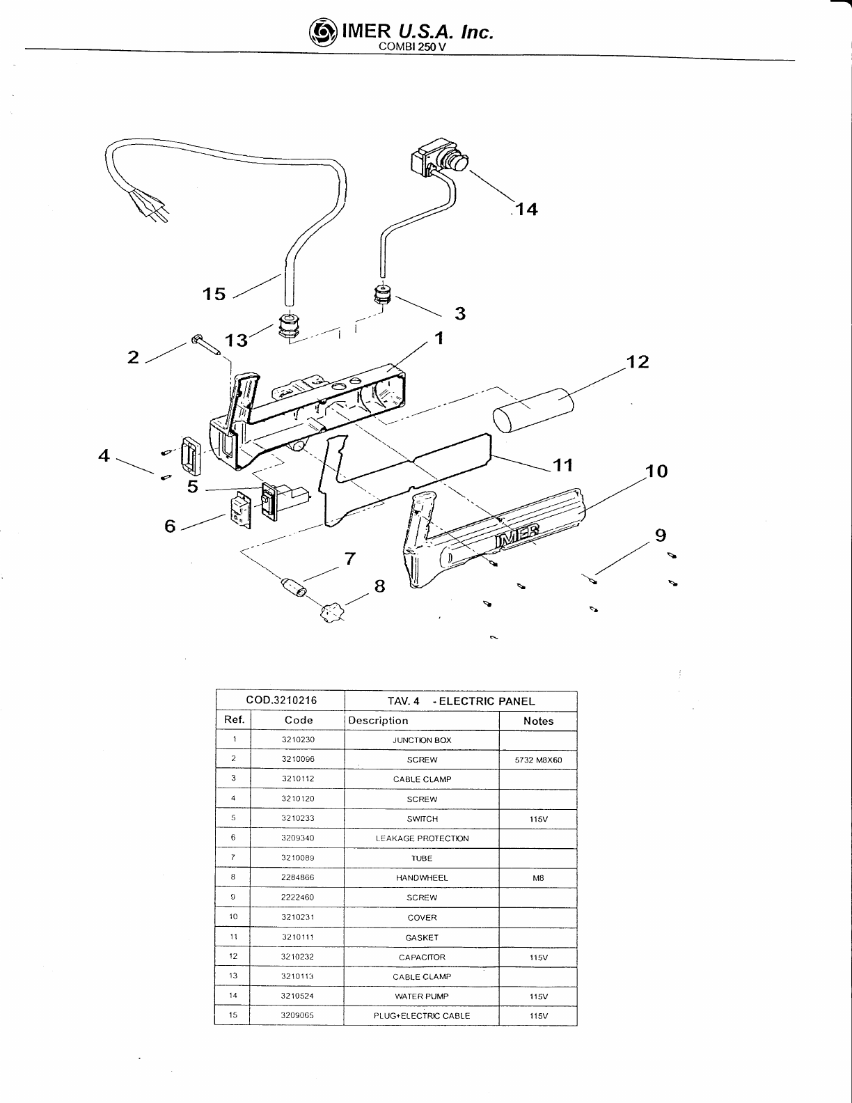
circuit.To do this, disassemble the deliverynozzle (ref. S lq.
4) locatedinsidethe blade guard
and cleanin water.
Periodically
clean the cooling water delivery line between the
pump and valve, (ref.V
fig. 7) and bladeguardusingwater.
corresponds to machine

@IMERU,;# tnc.
14. Troubleshooting
A-CaUf!ONt!! 4!!.maig.lenance oggrationsmust be
performed exctusivety with the maihine switc-ied-ii,
with the se/ector sef fo "0" and the power plug
disconnected from the mains-
power
pressed
but
motor
does
not
start.
- Power
cable
from
plug
topanel
is
disconnected.
- Electric
wire
loose
inside
motor
tei-minal
board.
- Electric
wire
loose
inside
panel.
- Start
switch
faulty.
not
cut.
-Socket
and
plug
not
fitted
corectlv. - Fitcorrecfly.
- Replace
cable
- Arrange
repairs
by electrician
- Arrange
repairs
by
electrician.
- Change
switch.
S1
C1
PE
N
L1
M1
lv12
Control switch
Capacitor
Earthing
cable
Neutrallinecable
Phase lineconductor
Blade motor
Pump motor
\oltage on
cooling
water
toblade.
erer
to "machtne c
tank
cleaning"
direction
ofblade
rotation-
- Blade
worn.
- ursassemble
blade
and
reposition
in the
direction as
shown on the
bladelabel.
- Fit new blade.

@IMERr/.*# tnc.
t8' SPARF P4RIS :All
orders
forspare
parts
mustindicate
thefollowing:
1- Typeof machine
.2- partnumbercnO po.iti* nr.r*Uu,.
each part.3 - Serial number and year of manufacture reported on the machine's identification
plate.
SYMBOL: Interchangeability
(example):Pos..1
P.n.
2222oo2was installed
on machincs
up toN; SZaOand pos.1.1 p.n. 2222O1Bin
onmachineN'5241 onwards.Pos.
1.1
isinterchangeable( )withPos. 1.Pos.
landPos. 1.1
arenotinterchangeableifthe( )s
appears in the table.
SPARE
PARTS TVOIES
Ref. Code
I2222002 SCREW 5240
2222018 SCREW 5241 _9
TAV.1 MACHINE STRUCTURE
Description
32
10055
22224
49 SCREW
2235
430
2224140 WAS
HE
R6593 8xl8
3207
076 WASHER NYLON 10.5x21xl
M8
5739 8x30
22S4866
2222005 SCREW
2223920
2?24
140 WASHER 6593 10x21
2222098 |
SCREW 5739 10x40
3210625
3210064 GONIOMETER
SUPPORT
32084
23 GONIOMETER
3209332
HANDWI]EEL
JZUOUbJ
32084
1
6GONIOMETER
PIN
3210060 L.n. JUKr^uf
3210061 R.H.
SURrnCe
SCREW 57396x16
3210087 SPRING
3210097 FRONT
ARM
2223280 5588
M6
3210099 SCREW
3210056 RIGHT
FENCE
ADHESIVE
LAEEL
a1)4qtt SCREW 59316x25
3210070
3210071 SUPPORT
3210063 GONIOMETER
ASSEMBLY
2224
530 WASHE
R6592 6x12.5
320
4eA5
3210069 FENCE
ADHESUVE
LABEL
3210068 SLIDEWAY
3210073 REARARM
3210057 LEFTFENCE
ADHESIVE
LABEL
3210018 FRAME

@IMERU,*#tnc.
,/'u
otP.'
) ,23
,a
\21
17
34
t'r F

@tMERu.*# rnc.
13
Q0t
6?
gr-
TAV.2 ASSEII,IBLY
OF MOTOR
Ref. Code Desc:'iption Notes
3210042 COVER
z321
0043 SPACER BRACKET
J320
133s SCREW s933
MBx25
32't0238 INNERFLANGE
3210046 OUTER FLANGE
732't00s3 NUT M12
SX
R3210218 MOTOR 11SV$OHz
32
10038 ENGINE
SUPPORT
10 2222541 SCREW 5739 M6x16
11 3210637 SCREW
12 2224380 WASHER 6s93
12X25
13 2223s20 NUT r,,t10
12\& ,t11
10
TAV.3 . BLADE
GUARD
Ref. Code. Description Notes
I32'tOO41 BLADEGJARD
3210050 SPRAYSHELD
2224535 V1IASFER
42223926 NUT AUTGL. t'44
2222!,01 SCRFW 5739ivilfl
o3209060 SCREW 5737l/6X35
73204399 SCREW 5931ft4525
a3210040 BLADE GJARD
2223924 NUT 55BBl\,6
10 3210047 cooiNTl-r6E
't1 22s2365 ruBE
tz 32078A4 CCCK

@IMERU.l;f
rnc.
@b,
)\
'4r' 14
I
6
--\ lg/ 9'/t I
2 -tt -'-, .13
$
4 r -.,_
-tt'
\ ---'
'c\/
\€}.
7./
\
\
B
\^.r-/
(>
ll:<t
coD.3210216 TAV.4 .ELECTRICPANEL
Ref Code Description Notes
13210230 JUNCTION BOX
23210096 SCREW s732
MBX60
3210112 CABLE CLAMP
3210120 SCREW
53210233 SWIICH 115V
63209340 LEAKAGE PROTECTION
73210089 TUBE
B2284866 HANDWHEEL M8
I2222460 aa Dtrl^t
10 3210231 an\/Eo
'l1321011'! GASKET
12 3210232 CAPACrIOR 115V
3210113 CABLE CLAMP
13210s24 WATER PUMP 115V
15 3209065 PLUG+ELECTRC
CABLE 115V

@tMERui;#.tnc,
,r9
N{s
/
b'
12
., ,2
,,. ,0.
coD.3210025 TAV.5 . CARRIAGE
Ref. Code Description N
otes
3210028 CARRIAGE BLOCK
232't0
105 qaatr\A/
33210627 RING
A3207397 WHEELASSEMBLY
52222114 SCREW
o3204945 BEARING 608 2RS1
a3210029 BLADEGUARD
I3210036 SCREW TCEI SX16
10 3210031 CARRIAGE
tl 3210032 CAM
12 3207393 SPACER BRACKET
13 3210622 SPACER BRACKET
14 2223920 NUT M10

@rME["g;;#
tnc.
coD.3210080 TAV
6.TRESTLE
ELEMENT
Ref. C
ode D
escription Notes
13210645 INTERNAL
TRESTLE
ELEMENT
23206205 TERMINAL
32071
93 RIGHTRABBET
.+ 3207194 LEFT
RABBET
52223924 NUT AUTOBL.MB
b2224204 WASHER 65938x24
73210641 EXTERNAL
TRESTLEELEMENT
I1222030 SCREW 5737Bx60
9321
0646 RUBBER
COATTING

@tlleRu.;# rnc.
ONE
YEAR
WARRANTY
We
warrant
to
the
originalpurchaser
thattheIMERequipment
described
herein
(the
"equipment")
shall
be
freefrom
defectsinmaterial
and
workmanship
under
normal
use
and
service
forwhich
itwas
intended
fora
period
of
one
(1)yearfrom
the
dateof
purchase
by
the
original
purchaser.
Our
obbligation
under
this
warranty
is
expressely
limited
toreplacing
orrepairing,
free
of charge,
F.O.B.
our
designated
servicefacility,
such
part
or parts
oftlre
equipment
as
our
inspection
shall
discloseto
bedefective.
Parts
such
asengines,
motors,
pumps,
valves,
electric
motors,
etc.furnished
byusbut
notmanifactured
by
us
will
carry
only
thewarranty
of
themanifacturer.
Transportation
chargesorduties
shall
be
borne
bythe
purchaser.
This
shall
be
thelimit
ofourliability
withrespect
to
the
quality
of
the
equipment
This
warranty
shall
not
apply
to
any
equipment,
or
parts
thereof,which
hasbeen
damaged
byreason
ofaccident,
negligence,
unreasonable
use,
faulty
repairs,
or
which
has notbeenmantained
andoperated
in accordance
withourprinted
instructions
for
our
equipment.
Further,
thiswarranty
isvoid
if
theequipment,
or
any
ofits
components,
is
altered
ormociified
inany
way.
THIS
WARRAI.JTY
ISEXPRESSLY
INLIEU
OFALL
CTHERWARM.NTIES,
EXPRESSED
OR IMPLIED,
INCLUDII{G,ANY
IMPLIED
WARRANTY
OF
MERCHANTABILIry
OFFITNESS
FORA
PARTICULAR
PURPOSE.
;
We
make
no
Other
warranty,
representation
or
guarantee,
nor
isanyone
authorized
to
make
one
on
our
behalf.
We
shallnot
beliable
for
anyconsequential
damage
of
any
kind,
including
loss
or
damage
resulting,
directly
orindirectly,
from
theuse
or
loss
ofuse
of
the
machine.
Without
limiting
the
generality
of
theforegoing,
this
exclusion
from
liability
embraces
the
purchase's
expenses
for
downtime,
damages
forwhich
the
purchaser
may
beliable
toother
persons,
damages
to
property,
and
injury
ordeath
of
any
persons.
This
warranty
shall
not
be
deemed
to
cover
maintenance
parts,
including
but
not
limited
to
blades,
belts,
hoses,
hydraulic
oilorfitters,
forwhich
we
shall
have
no
responsability
or
liability
whatsoever.
f
MER
U.S.A.,
lnc.
207
Lawrence
Avenue
South
San
Fancisco,
California
94080
(650)
872-2200
Other manuals for COMBI 250 V
2
Table of contents
Other IMER Saw manuals
Popular Saw manuals by other brands

DeWalt
DeWalt DW711 manual

EINHELL
EINHELL TC-SM 2131 Dual Original operating instructions

Hitachi
Hitachi C 10FCE Technical data and service manual

Jet
Jet AB-1012W Operating instructions and parts manual

Hitachi
Hitachi C 8FB2 Instruction manual and safety instructions

Parkside
Parkside PFS 710 B1 Operation and safety notes