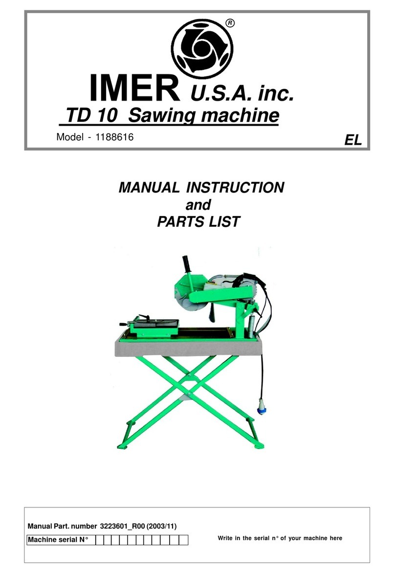
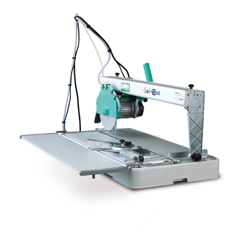
IMER MASONRY 350 Guide

IMER INTERNATIONAL S.p.A.
Via Salceto, 55 - 53036 Poggibonsi (SI) - Italy
Tel. +39 0577 97341 - Fax +39 0577 983304
www.imergroup.com
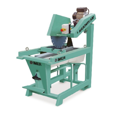
MASONRY 350
(1188780 230V 50Hz) - (1188784 110V 50Hz)
3201570 R07 - 2010/01
☞
I SEGATRICE
Manuale di uso, manutenzione e ricambi
F SCIE
Manuel utilisation entretien pieces de rechange
GB SAWING MACHINE
Operating, maintenance, spare parts manual
D MASCHINENSÄGE
Handbuch für Bedienung, Wartung und Ersatzteile
E TRONZADORA
Manual de uso, mantenimiento y recambios

2
MASONRY 350
IMER INTERNATIONAL S.p.A.
'$7,7(&1,&, '211((6
7(&+1,48(6 7(&+1,&$/'$7$ 7(&+1,6&+('$7(1 '$727(&1,&26
0DVRQU\
*LULODPD 7RXUVODPH %ODGHUSP 6lJHEODWWXPGUHKXQJHQ 5HYROXFLRQHVGHODKRMD
USP
'LDPHWURODPD 'LDPqWUHODPH %ODGHGLDPHWHU 6lJHEODWWGXUFKPHVVHU 'LjPHWURGHODKRMD
PP
)RURODPD 7URXODPH %ODGHPRXQWLQJKROH 6lJHEODWWERKUXQJ 2ULILFLRGHODKRMD
PP
3RWHQ]DPRWRUH 3XLVVDQFHPRWHXU 0RWRUUDWLQJ 0RWRUOHLVWXQJ 3RWHQFLDGHOPRWRU
.Z
*LULPRWRUH 7RXUVPRWHXU 0RWRUUSP 0RWRUGUHK]DKO 5HYROXFLRQHVGHOPRWRU
USP
'LPHQVLRQLSLDQRGL
WDJOLR 'LPHQVLRQVSODQGH
FRXSH &XWWLQJWDEOHGLPHQVLRQV 0DH6FKQHLGIOlFKH 'LPHQVLRQHVGHODPHVD
GHFRUWH
PP [
'LPHQVLRQLGLLQJRPEUR 'LPHQVLRQV
GHQFRPEUHPHQW 2YHUDOOGLPHQVLRQV 5DXPEHGDUI 'LPHQVLRQHVWRWDOHV
PP [[
'LPHQVLRQLGLLQJRPEUR
SHUWUDVSRUWR
'LPHQVLRQV
GHQFRPEUHPHQWSRXU
WUDQV
2YHUDOOGLPHQVLRQVIRU
WUDQVSRUW 7UDQVSRUWUDXPEHGDUI 'LPHQVLRQHVWRWDOHV
SDUDHOWUDQVSRUWH
PP [[
3HVR 3RLGV :HLJKW *HZLFKW 3HVR
.J
3HVRSHUWUDVSRUWR 3RLGVSRXUWUDQVSRUW :HLJKWIRUWUDQVSRUW 7UDQVSRUWJHZLFKW 3HVRSDUDHOWUDQVSRUWH
.J
'LUH]LRQHURWD]LRQHODPD
YLVWDGDOODIODQJLDGL
VHUUDJJLRODPD
'LUHFWLRQURWDWLRQODPH
YXHGHSXLVODEULGHGH
VHUUDJHODPH
%ODGHURWDWLRQ
GLUHFWLRQVHHQIURP
EODGHFODPSLQJIODQJH
6lJHEODWWGUHKULFKWXQJ
YRP
6lJHEODWWKDOWHUIODQVFK
DXVJHVHKHQ
6HQWLGRGHURWDFLzQGH
ODKRMDYLVWRGHVGHOD
EULGDGHDSULHWHGHOD
KRMD
$17,25$5,2
6(16,19(56
$17,&/2&.:,6(
*(*(18+5=(,*(56,11
$17,+25$5,2
&RUUHQWHDVVRUELWD &RXUDQWDEVRUEp &XUUHQW 6WURPDXIQDKPH &RUULHQWHDEVRUELGD
$
7HQVLRQH 7HQVLRQ 9ROWDJH 6SDQQXQJ 7HQVLzQ
9
)UHTXHQ]D )UpTXHQFH )UHTXHQF\ )UHTXHQ] )UHFXHQFLD
+]
),*
*$0%$7(/(6&23,&$ &2/211(7e/(6&23,48( 7(/(6&23,&/(* 7(/(6.233)866 3,(7(/(6&23,&2
*5(0%,$/,1$
3$5$6358==, %$92/(7 635$<*8$5' 635,7=6&+87= 3/$&$'(/$17$/
6$/3,&$'85$6
02725( 027(85 02725 02725 02725
%5$&&,23257$/$0$ %5$63257(/$0( %/$'(6833257$50 6b*(%/$77+$/7($50 %5$=23257$&8&+,//$
3203$$&48$ 3203($($8 :$7(53803 :$66(53803( %20%$'(/$*8$
*8,'$6&255,0(172 &28/,66( *8,'( */(,7)h+581* *8,$'('(6/,=$0,(172
,17(5587725(
*(1(5$/( ,17(55837(85*e1e5$/ ,0$,16:,7&+ +$8376&+$/7(5 ,17(5583725*(1(5$/
3,$12',7$*/,2 3/$1'(&283( :25.7$%/( 6&+1(,')/b&+( 683(5),&,('(&257(
9$6&$$&48$ &89($($8 :$7(57$1. :$66(5%(&.(1 '(326,72'($*8$
3527(=,21(/$0$ 3527(&7,21'(/$/$0( %/$'(*8$5' 6b*(%/$779(5./(,'81* 3527(&&,21&8&+,//$
9,7(',0(66$$7(55$ 9,6'(0,6($/$7(55( ($57+,1*6&5(: (5'81*66&+5$8%( 7251,//2'(38(67$$
7,(55$
%/2&&$**,27(67$ &$/$*('(/$7(7( +($'/2&.,1* .23))(6767(//81* %/248(2'(/$&$%(=$

3
MASONRY 350
IMER INTERNATIONAL S.p.A. I
Caro Cliente,
ci complimentiamo per il suo acquisto: la segatrice IMER, risultato
di anni di esperienza, è una macchina di massima affidabilità e
dotata di soluzione tecniche innovative.
OPERARE IN SICUREZZA.
E fondamentale ai fini della sicurezza leggere attentamente le
seguenti istruzioni.
- Il presente manuale di USO E MANUTENZIONE deve essere cu-
stodito dal responsabile di cantiere nella persona del
CAPOCANTIERE nel cantiere stesso, sempre disponibile per la
consultazione.
- Il manuale è da considerarsi parte della macchina e deve essere
conservato per futuri riferimenti (EN 292/2) fino alla distruzione
della macchina stessa. In caso di danneggiamento o smarrimento
potrà essere richiesto al costruttore un nuovo esemplare.
- Il manuale contiene importanti indicazioni sulla preparazione del
cantiere, linstallazione, luso, le modalità di manutenzione e la
richiesta di parti di ricambio. Comunque è da ritenersi indispensa-
bile una adeguata esperienza e conoscenza della macchina da
parte del montatore e dellutilizzatore.
- Affinchè sia possibile garantire la sicurezza delloperatore, la si-
curezza di funzionamento e una lunga durata della macchina devo-
no essere rispettate le istruzioni del manuale, unitamente alle nor-
me di sicurezza e prevenzione degli infortuni sul lavoro secondo la
legislazione vigente. Fare uso delle protezioni individuali (scarpe di
sicurezza, guanti sec. D.P.R. 164 , D.P.R. 547 e D.L.626/94).
Particolare attenzione deve essere fatta alle avvertenze
contrassegnate con questo simbolo :
É obbligatorio l' uso degli occhiali o dello schermo
di protezione.
MANTENERE SEMPRE LEGGIBILI LE ETICHETTE DI
AVVERTENZA.
E vietato apportare modifiche di qualsiasi natura alla
struttura metallica o impiantistica della macchina.
- La IMER International declina ogni responsabilità in caso di non
osservanza delle leggi che regolano luso di tali apparecchi, in par-
ticolare: uso improprio, difetti di alimentazione, carenza di manu-
tenzione, modifiche non autorizzate, inosservanza parziale o tota-
le delle istruzioni contenute in questo manuale.
1. NORME DI PROGETTO
La segatrice MASONRY 350 è stata progettata e costruita applicando le
seguenti norme: I.E.C. 34-4; EN 292 (91/368/CEE); CEI EN 60204.
2. LIVELLO EMISSIONE SONORA
Il livello di emissione sonora all' orecchio dell' operatore (livello pres-
sione acustica continuo equivalente ponderato "A"), misurato du-
rante il taglio con lama a corona continua, é di 93 db(A).
3. SPECIFICHE DI TAGLIO
La segatrice IMER è progettata per tagliare esclusivamente lateri-
zi, ceramiche, marmo, granito, manufatti in cemento e simili. De-
vono essere usate esclusivamente lame diamantate a corona con-
tinua o a settori con interruzioni sottili sempre refrigerati ad acqua.
Non si devono assolutamente usare lame per taglio a secco e non
si deve tagliare altro materiale non previsto in questa specifica. La
IMER INTERNATIONAL declina ogni responsabilità sui danni deri-
vati da un uso improprio dell'apparecchiatura.
4. CAPACITÀ DI TAGLIO
-Capacità di taglio massima con lama verticale = 120mm.
-Capacità di taglio massima con lama inclinata a 45° = 30mm.
-Dimensioni minime dei pezzi da tagliare:larghezza minima = 50mm.
-Dimensioni massime dei pezzi da tagliare:
Lama verticale abbassata :
b x h x l = 500 x 25 x 480
= 500 x 60 x 450
= 500 x 120 x 400
Lama verticale alzata, inizio taglio con discesa dall'alto :
b x h x l = 500 x 120 x 450
Lama inclinata a 45°:
b x h x l = 500 x 30 x 480
5.AVVERTENZE
- Non caricare la macchina con pezzi di peso eccessivo (max
Kg.40).
- Fare attenzione alla stabilità sia dei pezzi prima, durante e dopo
il taglio che della macchina: i pezzi in ogni caso non devono spor-
gere fuori dal piano di lavoro.
- Evitare di disperdere nell'ambiente i liquidi residui del taglio predi-
sponendo idonei contenitori.
6. MISURE DI SICUREZZA
- La segatrice IMER è stata progettata per lavorare in cantieri edili
in condizione di illuminazione solare ed in laboratori in condizioni di
illumizione naturale o artificiale non inferiore ad almeno 500 LUX.
Non deve essere usata in ambienti ove esista perico-
lo di esplosioni e/o incendi o in ambienti di scavi sotterranei.
- La segatrice IMER può funzionare soltanto se munita di tutti i
disposititvi di protezione in perfette condizioni.
- Non usare linee di alimentazione improvvisate e/o difettose.
- Le linee di allacciamento nel cantiere devono essere posate in
modo tale da non poter essere danneggiate. Non collocare la
segatrice sul cavo di alimentazione.
- Le connessioni presa-spina devono essere posate in modo tale
da impedire la penetrazione di acqua. Usare soltanto connettori
muniti di protezione contro i getti dacqua (IP55).
- Le riparazioni degli impianti elettrici devono essere eseguite esclu-
sivamente da personale specializzato. Non effettuare operazioni di
registrazione o manutenzione con macchina in tensione o in movi-
mento.
- La macchina va collegata all'impianto
equipotenziale di terra del cantiere con una trec-
cia di sezione minima di 16mm²,il punto di colle-
gamento è identificato con una vite saldata sul te-
laio (vedi Fig.1 )e dalla targhetta con il simbolo di
terra.
- Per fermare la segatrice usare esclusivamente l'ap-
posito interruttore.
- Il simbolo rappresentato sull' etichetta (a sinistra)
sta ad indicare che "É VIETATO AZIONARE LA MAC-
CHINA SE LE PROTEZIONI NON SONO MONTATE
ED EFFICIENTI".
7. SICUREZZA ELETTRICA
La segatrice IMER risponde alla norma EN 60204-1e in particolare
è dotata:
- Sistema contro il riavviamento intempestivo dopo un' interruzione
di alimentazione;
- Protezione contro i cortocircuiti;
- Protezione termica del motore.
8. TRASPORTABILITÀ (Rif. Fig. 2)
ATTENZIONE! Prima di rimuovere la segatrice stac-
care sempre la spina di alimentazione e bloccare lo scorri-
mento del carrello portatesta con l'apposito pomello rif.3. Per
il trasporto della macchina usare un tirante a quattro braccia,
impegnando i ganci negli appositi attacchi.
9. INSTALLAZIONE (Rif. Fig. 2)
- Sballare la macchina e sollevarla usufruendo di un tirante a quat-
tro braccia impegnando i ganci negli appositi attacchi.
- Sbloccare le gambe sfilando i perni rif.1 .
- Bloccare le gambe all'altezza di lavoro reinserendo i perni nei fori
dei portagambe.
- Posizionare la macchina su un piano orizzontale in modo stabile.
10. ALLACCIAMENTO ALLA RETE ELETTRICA
- Assicurarsi che la linea elettrica sia provvista di pro-
tezione differenziale a monte.Utilizzare, se necessario, il di-
spositivo di sicurezza differenziale (RCD) a innesto rapido IMER
(cod.1169245) disponibile in kit per le macchine a 230V.
EN ISO 12100-2
EN ISO 12100-1/2 ; EN 60204-1 ; UNI EN 12418

I
- Verificare che la tensione di alimentazione sia corretta per il colle-
gamento della macchina : 230V/50 oppure 110V/50Hz.
La linea dell'alimentazione elettrica deve essere adeguatamente
dimensionata per evitare cadute di tensione.Occorre anzitutto evi-
tare l'impiego di tamburi per cavi (con anelli collettori).
Le dimensioni del conduttore devono basarsi sulla corrente di av-
viamento e sulla lunghezza della linea.Di norma è sufficiente un
conduttore di 4x4mm²,sino a 50mt.Dopo l'installazione è in ogni
caso necessario eseguire una misurazione della tensione,con il
carico,sia in sede di avviamento che di funzionamento.Durante il
funzionamento la perdita di tensione deve essere limitata al 5%.In
presenza di conduttori più lunghi o di una rete non ottimale usare
una sezione di almeno 6mm².I cavi di alimentazione utilizzati sul
cantiere devono avere un idoneo rivestimento esterno resistente
allo schiacciamento e all'usura oltre che agli agenti atmosferici.
- Per la conformità dell'impianto di alimentazione attenersi
alla norma CEI-64-8 (documento di armonizzazione CENELEC
HD384).
11. MESSA IN SERVIZIO DELLA MACCHINA
Prima di collegare elettricamente la macchina:
1 - Assicurarsi che il telaio metallico sia stato collegato alla terra
come indicato al CAP. 6 " Misure di sicurezza ".
2 - Verificare che la vasca contenga una quantità sufficiente di ac-
qua di raffreddamento.
3 - Assicurarsi che il circuito di alimentazione risponda ai requisiti
prescritti al CAP.10 " Allacciamento alla rete elettrica".
4 - Quindi collegare la macchina alla linea elettrica di alimentazio-
ne.
5 - Portare l'interruttore in posizione " 1 " e quando il motore è
avviato riportarlo in posizione " 0 " avendo verificato il normale af-
flusso dell'acqua di raffreddamento.
6 - Controllare il senso di rotazione della lama secondo la freccia
posta sul carter di protezione.
7 - Se tutto è in ordine il lavoro può iniziare.
12. EMERGENZA - STOP
- In caso di emergenza arrestare la macchina pre-
mendo sul comando di arresto dell'interruttore.
- Il motore è protetto dai sovraccarichi termici,in caso
di surriscaldamento si arresta. Far raffreddare e riportare l'in-
terruttore su 0 e avviare di nuovo.
- Il motore è protetto contro il riavvio intempestivo al
ritorno della tensione dopo un'interruzione dovuta a mancan-
za di energia elettrica. Per riprendere il lavoro al ritorno della
tensione riportare l'interruttore su 0 e avviare di nuovo.
13. MONTAGGIO LAMA (Rif.Fig.3)
Togliere la vite anteriore rif.1 e allentare le altre due viti rif.2 che
bloccano la protezione lama rif.3 con chiave esagonale N°10.Ruotare
la protezione in senso orario in modo da rendere accessibile la vite
di bloccaggio rif.4,usare la chiave n°13 per toglierla ruotando in
senso antiorario.Togliere la flangia mobile.Controllare che non vi
siano danni su flange,albero disco e lama.
- Non usare lame deteriorate.
- Usare solo lame adatte al numero di giri riportato
sulla targhetta della macchina.
- Controllare che il senso di rotazione della lama sia
come quello riportato sul carter lama.
Centrare la lama sulla flangia fissa,posizionare la flangia mobile e
stringere la vite di bloccaggio usando la chiave n°13 ruotando in
senso orario.Riportare la protezione nella posizione iniziale e bloc-
care con le viti rif.1 e rif.2.
- Assicurarsi che la protezione lama (rif.3) sia ben
fissata.
- ATTENZIONE!!! Una lama non correttamente
montata,una vite di bloccaggio non sufficientemente
stretta,possono provocare danni alla macchina e alle persone.
- Si ricorda che la lama deve avere diametro esterno
di 350 mm,foro centrale di diametro 25,4 mm e spessore max.3
mm.
Assicurarsi che la lama che intendete usare sia adeguata al
materiale da tagliare.
- E' vietato l'uso di dischi da legno.
- Non usare dischi diamantati segmentati con asole maggiori di
5 mm.
15. USO
Lasciatevi 150 cm di spazio libero intorno alla mac-
china per poter operare in sicurezza.
- Non permettete che altre persone rimangano vicino alla macchina
durante il taglio.
- Non usate la macchina in zona a pericolo di incendio.Eventuali
scintille possono provocare incendi o esplosioni.
- Posizionare e trasportare la macchina solo dopo aver tolto l'alimen-
tazione.
- Assicurarsi sempre che la lama non sia a contatto di qualcosa
prima di avviare il motore.
- Controllare che la protezione del disco sia al suo
posto.
- Controllare che il senso di rotazione della lama sia
come quello riportato sul carter lama.
- Prima di iniziare il lavoro riempire la vasca d'acqua.Curare il ripristi-
no del livello quando,durante l'uso,si rendesse necessario:il pescante
della pompa deve rimanere sempre immerso!
- Inserire la spina di alimentazione.
- ATTENZIONE!!! È Assolutamente vietato correre
degli inutili rischi di infortunio, rimuovendo le protezioni della
macchina.
- Il motore è protetto contro il sovraccarico termico:
tale protezione interviene arrestando la macchina, dopodichè
si deve attendere il tempo necessario al raffreddamento del di-
spositivo termico prima di poter riavviare la macchina.
ATTENZIONE!!! Tutte le operazioni di regolazione della
lama devono essere eseguite a motore spento.
14.1 MOVIMENTO VERTICALE DELLA LAMA (Rif.Fig.4)
Per alzare o abbassare la lama è necessario allentare l'impugnatu-
ra (Rif.2),ruotando la stessa in senso antiorario.Il supporto lama
(Rif.1) rimane libero di ruotare,quindi lo si può fissare nella posizio-
ne voluta,ruotando a fondo l'impugnatura (Rif.2).
Assicurarsi che l'impugnatura di bloccaggio sia ben
serrata prima di iniziare il lavoro.
14.2 POSIZIONAMENTO DELLA LAMA PER TAGLI A45°
(Rif.Fig.5)
- Allentare il dispositivo a vite di bloccaggio (Rif.1), il braccio
portalama (Rif.2) è libero di ruotare e lo si può posizionare a fine
corsa,cioè con l'inclinazione della lama a 45° rispetto al piano;serrare
nuovamente a fondo il dispositivo di bloccaggio
- Per riportare la lama in posizione verticale (POS.0),eseguire l'ope-
razione inversa alla precedente.
- Assicurarsi che il dispositivo di bloccaggio (Rif.1)
sia ben serrato prima di iniziare il lavoro.
14.3 TAGLIO
- Controllare la posizione della lama rispetto alla li-
nea di taglio e che l'impugnatura e le viti di bloccaggio siano
ben strette.
- Disporre il pezzo da tagliare sul carrello portapezzo, appoggiato
in modostabile alla battuta fissa dello stesso. Avviare il motore.
Attendere che l' acqua arrivi alla lama. Iniziare il taglio.
- Il movimento orizzontale di taglio si realizza spingendo in basso
la testa con la apposita maniglia (rif.1, fig.6) e facendo avanzare il
carrello portapezzo verso la lama.
- Più aumenta l'altezza di taglio,maggiore è il lavoro
necessario alla lama per asportare il materiale.Quindi per non
sovraccaricare il motore,l'operatore dovrà controllare la velo-
cità di avanzamento del carrello.Tale velocità dipende anche
dalle caratteristiche del materiale da tagliare
MASONRY 350
IMER INTERNATIONAL S.p.A.
4

5
MASONRY 350
IMER INTERNATIONAL S.p.A. I
(durezza,tenacità,ecc....).
14.3.1 TAGLIO CON DISCESA DALL'ALTO
-Portare il supporto lama nella posizione più alta.Posizionare il pez-
zo da tagliare.Avviare la macchina iniziare il taglio in verticale fino
alla posizione più bassa e proseguire il taglio in orizzontale.
14.3.2 CAMBIO DELLA LAMA
Per il cambio della lama riferirsi al cap.13. MONTAGGIO LAMA.
15. MANUTENZIONE
ATTENZIONE!!! Prima di qualsiasi manutenzione
occorre sempre spengere la macchina e staccare la spina di
alimentazione.
- Mantenere sempre efficienti e integre le protezioni.
- Assicurarsi sistematicamente dello stato del cavo
elettrico ogni qualvolta si inizia l'uso della macchina,qualcuno
inavvertitamente e/o inconsapevolmente potrebbe averlo dan-
neggiato.
Non abbandonare la macchina all'aperto,ma lasciarla al riparo dalle
intemperie.
- Sostituire componenti usurati o guasti con pezzi di ricambio origi-
nali.
- in caso di smontaggio del motore o del quadro elet-
trico, sostituire sempre le relative guarnizioni (guarnizione
motore-testa e guarnizione coperchio-testa rif. 22 e 13, Tav. 3),
la cui efficienza è essenziale per garantire la tenuta alla
penetrazione di acqua dell'involucro contenente i comandi
elettrici.
15.1 PULIZIA VASCA A FINE LAVORO
- Al termine del lavoro è opportuno smontare la vasca dopo averla
svuotata e rimuovere mediante abbondante lavaggio il deposito di
taglio che vi si fosse formato.
15.2 SMONTAGGIO VASCA (Rif.Fig.7).
- Sollevare la vasca rif.1 in modo da disimpegnarla dai supporti rif.2
e farla uscire dal lato indicato dalla freccia.
15.3 PULIZIA PIANI DI RIFERIMENTO
I piani di appoggio devono essere mantenuti puliti.Depositi di spor-
co su dette superfici possono determinare imprecisioni di taglio.
15.4 PULIZIA GUIDE DI SCORRIMENTO
È opportuno rimuovere dalle guide ogni traccia di sporco che vi si
formasse.
15.5 PULIZIA E MANUTENZIONE IMPIANTO
RAFFREDDAMENTO
- Se l'acqua non arriva arrestare immediatamente il taglio per non
rovinare la lama.
- Dopo aver spento la macchina verificare che il livello dell'acqua
nella vasca sia sufficiente.
- Se necessario, dopo aver scollegato la spina di alimentazione
controllare che non vi siano ostacoli nel rubinetto, nel tubo o nel
filtro della pompa.
- Se occorre, verificare che la girante giri liberamente (dopo lunga
inattività.)
- Eventualmente smontare la pompa e vedere se il giunto girante/
motore è efficiente.
15.6 SOSTITUZIONE DELLA CINGHIA DI TRASMISSIONE
- Scollegare la macchina dalla presa di alimentazione.
- Scollegare il tubo dell'acqua del distributore posto sul carter lama
allentando l'apposita fascetta.
- Togliere la lama rimuovere le due flange, le viti di unione dei due
semicarter, la maniglia di bloccaggio (Rif.1, Tav. 2) e togliere il
semicarter esterno lato motore.
-Spostare l'albero portalama con puleggia dalla sede del cuscinetto
(Rif.27, Tav. 2) e posizionarlo nella sede del cuscinetto (Rif.14, Tav.
2) sul semicarter precedentemente rimosso.
- Inserire la nuova cinghia nelle due puleggie e riposizionare il
tendicinghia.
- Sostituire la guarnizione sul bordo del carter (Tav.2, rif. 52), la cui
efficienza è fondamentale per impedire la penetrazione di acqua nel-
l'involucro contenente i comandi.
- Verificare che le due spine di centraggio siano in posizione.
- Rimontare il carter inserendo l'albero lama nella sede del cuscinet-
to (Rif.27, Tav. 2) e posizionando la vite (Rif.51, Tav. 2) posta nell'aso-
la fulcro testa (Rif.19, Tav. 2) in corrispondenza del foro per la mani-
glia di bloccaggio (Rif.1, Tav. 2).
- Avvicinare i due semicarter usando le due spine come centraggio.
- Avvitare i due semicarter in croce.
- Riavvitare la maniglia di bloccaggio prima di rimontare la lama.
16. INCONVENIENTI / CAUSE / RIMEDI
ATTENZIONE!!! Tutti gli interventi di manutenzione
devono essere eseguiti dopo aver fermato la macchina, posi-
zionando il selettore su "0" e staccando la presa di alimenta-
zione.
,QFRQYHQLHQWL &DXVH 5LPHGL
3UHPHQGR
OLQWHUUXWWRUHLO
PRWRUHQRQSDUWH
1RQDUULYDWHQVLRQH
VXOODOLQHDGL
DOLPHQWD]LRQH
/DSUHVDHODVSLQD
HOHWWULFDQRQVRQREHQ
FROOHJDWH
,OFDYRGL
DOLPHQWD]LRQHGDOOD
VSLQDDOTXDGURq
VWDFFDWR
8QILORHOHWWULFR
DOOLQWHUQRGHOOD
PRUVHWWLHUDPRWRUHq
VWDFFDWR
8QILORHOHWWULFR
DOOLQWHUQRGHOTXDGURq
VWDFFDWR
/LQWHUUXWWRUHGL
PDUFLDqJXDVWR
(LQWHUYHQXWRLO
GLVSRVLWLYRGL
VLFXUH]]DWHUPLFR
&RQWUROODUHODOLQHD
5LSULVWLQDUHXQFRUUHWWR
FROOHJDPHQWR
&DPELDUHLOFDYR
&ROOHJDUHGLQXRYR
&ROOHJDUHGLQXRYR
6RVWLWXLUHOLQWHUUXWWRUH
$WWHQGHUHTXDOFKH
PLQXWRHULSURYDUHGL
QXRYR
6FRUULPHQWRYHUWLFDOH
GHOODODPDIRU]DWR
,OSRPHOORGL
EORFFDJJLRpVWUHWWR $OOHQWDUH
,QFOLQD]LRQHODPD
IRU]DWR
/DYLWHGLEORFFDJJLR
pVWUHWWD $OOHQWDUH
6FRUULPHQWR
RUL]]RQWDOHFDUUHOOR
GLIILFROWRVR
,OSRPHOORGL
EORFFDJJLRqVWUHWWR
5XRWLQDVFRUULPHQWR
UHJRODWDPDOH
$OOHQWDUH
5HJLVWUDUH&$3
1RQDUULYDDFTXDGL
UHIULJHUD]LRQHDOOD
ODPD
5LIHULUVLDOODSXOL]LDHPDQXWHQ]LRQH
GHOOLPSLDQWRGLUDIIUHGGDPHQWR&$3
/DODPDQRQWDJOLD
6HQVRGLURWD]LRQH
ODPDFRQWUDULR
/DODPDqXVXUDWD
6PRQWDUHODODPDH
ULSRVL]LRQDUODQHOVHQVR
LQGLFDWRQHOOHWLFKHWWD
GHOODODPD
0RQWDUHXQDQXRYD
ODPD
,OPRWRUHVLDYYLDPD
ODODPDQRQUXRWD
5RWWXUDFLQJKLD 6RVWLWX]LRQHFLQJKLDGL
WUDVPLVVLRQH&$3

6
MASONRY 350
IMER INTERNATIONAL S.p.A. F
Cher Client,
Nous vous félicitons de votre achat: la scie IMER, résultat de
plusieurs années dexpérience, est une machine de grande fiabilité
dotée de solutions techniques à lavant-garde.
OPERER EN SECURITE
Il est fondamental, pour travailler en toute sécurité, de lire
attentivement les instructions qui suivent.
- Le présent manuel USAGE ET ENTRETIEN doit être conservé
par le responsable du chantier cest-à-dire le chef de chantier en
personne, et doit toujours être disponible pour la consultation.
- Le manuel doit être considéré comme partie intégrante de la
machine et doit être conservé pour les références futures (EN 292/
2) jusquà la destruction de la machine. En cas dendommagement
ou de perte, un nouvel exemplaire pourra être demandé au
constructeur.
- Le manuel contient des indications importantes sur la préparation
du chantier, linstallation, lutilisation, les modalités dentretien et
la demande de pièces de rechange. Une expérience appropriée et
une bonne connaissance de la machine de la part de linstallateur
et de lutilisateur sont à considérées comme indispensables.
- Pour garantir la sécurité absolue de l'opérateur, un fonctionnement
parfait et la longévité de l' appareil, respecter les instructions du
manual ainsi que les régles de sécurité et de prévention contre les
accidents du travail conformément à la en viguer. Porter des
chaussures et des vêtements appropriés ainsi que des gants
selonD.N°92-765/766/767 et L233-84).
Il faut prêter une attention toute particulière aux notes
précédées de ce symbole:
Il est obligatoire de porter des lunettes ou un écran
de protection.
LES SIGNALISATIONS DOIVENT TOUJOURS ETRE
BIEN LISIBLES.
Il est interdit dapporter des modifications, de quelque
nature que ce soit, à la structure métallique ou à lingénierie
de la machine.
La société IMER INTERNATIONAL décline toute responsabilité en
cas de non-respect des lois régissant lutilisation de ces appareils,
en particulier: usage impropre, défauts dalimentation, manque
dentretien, modifications non autorisées, non-respect partiel ou
total des instructions contenues dans ce manuel.
1. NORMES DE PROJET
La Scie MASONRY 350 a été conçue et construite en appliquant
les normes suivantes: I.E.C.34.4;EN 60204-1;EN 89/392 (91/
368CEE).
2. NIVEAU D'ÉMISSION SONORE
Niveau d'émission sonore perceptible à loreille de lopérateur (niveau
continu équivalent de pression acoustique pondéré A): le niveau
démission sonore de la tronçonneuse MASONRY 350 en condition
de travail avec lame à couronne continue est de 93 db(A).
3. CARACTERISTIQUES DE COUPE
La tronçonneuse IMER a été conçue pour couper exclusivement
les briques, la céramique, le marbre, le granit, les produits
manufacturés en ciment et similaires. Elle monte exclusivement
des lames diamantées à couronne continue ou à secteurs toujours
réfrigérés à eau. Ne jamais utiliser de lames prévues pour la coupe
à sec et ne couper aucun autre matériau que ceux cités auparavant.
IMER INTERNATIONAL décline toute responsabilité pour tout
dommage causé par une utilisation impropre de la machine.
4. PROFONDEUR DE COUPE
- Profondeur de coupe maxi avec lame verticale = 120 mm
- Profondeur de coupe maxi avec lame inclinée à 45° = 30 mm
- Dimensions minimales des pièces à couper: largeur mini = 50
mm
- Dimensions maximales des pièces à couper:
Lame verticale abaissée: b x h x l = 500 x 25 x 480
= 500 x 60 x 450
= 500 x 120 x 400
Lame verticale relevée, début de coupe avec descente à partir du
point supérieur: b x h x l = 500 x 120 x 450
Lame inclinée: b x h x l = 500 x 30 x 480
5. RECOMMANDATIONS
- Ne pas charger la machine avec des pièces trop lourdes /40 kg
maximum).
- Sassurer que les pièces sont stables avant et pendant la coupe;
si nécessaire, prévoir des plans dappui supplémentaires disposés
à la même hauteur que le plan de coupe.
- Éviter dabandonner dans la nature les liquides résiduels de coupe
en les stockant dans des barils prévus à cet effet.
6. MESURES DE SECURITE
- La tronçonneuse IMER a été conçue pour être utilisée sur les
chantiers de construction, exposée au soleil ou dans des ateliers,
en conditions d'éclairage naturel ou artificiel non inférieur à 500
LUX.
Ne pas l'utiliser dans des locaux présentant un danger
d'explosion et/ou d'incendie ou dans des cavages sous-terrains.
- La tronçonneuse IMER peut fonctionner uniquement si elle est
munie de tous les dispositifs de protection en parfait état.
- Ne pas allumer la tronçonneuse si la ligne électrique est
défectueuse ou improvisée.
- Les lignes de raccordement du chantier doivent être posées de
sorte à ne pas être endommagées. Ne pas installer la machine au-
dessus de ces lignes.
- Les lignes de raccordement doivent être installées de sorte à
protéger les connecteurs contre les infiltrations d'eau. N'utiliser que
des connecteurs munis de protection contre les jets d'eau (IP55).
- Seul le personnel spécialisé peut intervenir sur les installations
électriques. Ne pas mettre la tronçonneuse en marche au cours
des opérations d'entretien et de réparation.
- Relier la machine à la mise à la terre du
chantier présentant la même puissance; utiliser une
tresse de 16 mm² de section minimale
; le point de
raccordement est reconnaissable grâce à une vis
soudée sur le châssis (voir fig.1) et à une plaquette
portant le symbole de terre.
- Éteindre la machine uniquement en agissant sur
l'interrupteur.
- Le symbole reproduit sur l'étiquette (à gauche)
indique qu'"IL EST INTERDIT DE METTRE LA
MACHINE EN MARCHE SI LES PROTECTIONS NE
SONT PAS MONTÉES OU NE SONT PAS EN BON
ÉTAT".
7. SECURITE ELECTRIQUE
La tronçonneuse IMER répond EN 60204-1.
Elle est équipée de:
- Système contre le démarrage automatique après coupure de
courant.
- Protection contre les court-circuits.
- Protection thermique du moteur.
8.TRANSPORT (Rep. Fig.2)
ATTENTION: Toujours débrancher la tronçonneuse
et bloquer la glissière du chariot porte-têtes à l'aide du pommeau
rep.3 avant de déplacer la tronçonneuse. Pour transporter la
machine, utiliser un tirant à quatre bras et fixer les crochets
dans les fixations prévues à cet effet.
9. INSTALLATION (Rep.Fig.2)
- Déballer la machine et la soulever à l'aide d'un tirant à quatre bras
en fixant les crochets dans les fixations prévues à cet effet.
- Débloquer les colonnes en dégageant les goujons rep.1.
- Bloquer les colonnes à la hauteur de travail en replaçant les goujons
dans les trous des porte-colonnes.
- Positionner la machine sur un plan horizontal de sorte qu'elle soit
stable.
10. CONNEXION AU RESEAU ELECTRIQUE
- Sassurer que la ligne électrique est équipée dune
protection différentielle en amont. Utiliser, si nécessaire, le
EN ISO 12100-2
EN ISO 12100-1/2 ; EN 60204-1 ;
UNI EN 12418

7
MASONRY 350
IMER INTERNATIONAL S.p.A.
dispositif de sécurité différentiel (RCD) à raccord rapide IMER
(code 1169245) disponible en kit.
- Vérifier que la tension dalimentation est correcte pour le
raccordement de la machine: 230V/50Hz - 110V/50Hz.
- Pour être en règle, linstallation dalimentation doit
être conforme aux normes CEI 64-8 (document dharmonisation
CENELEC HD384).
- La ligne de l'alimentation électrique doit être dimensionnée de
sorte à éviter les chutes de tension. Éviter l'utilisation de tambours
pour câbles (avec anneaux collecteurs).
Les dimensions du conducteur doivent être calculées en fonction
du courant de démarrage et de la longueur de la ligne. En général,
on utilise un câble de 4 x 4 mm² pouvant aller jusqu'à 50 m de long.
Une fois l'installation terminée, mesurer la tension, en charge, au
moment de l'allumage et en cours de fonctionnement. En cours de
fonctionnement, la chute de tension doit être limitée à 5%. En
présence de conducteurs plus longs ou d'un réseau défectueux,
utiliser un câble de section minimum 6 mm². Les conducteurs utilisés
sur le chantier doivent avoir un revêtement externe qui résiste à
lécrasement, à lusure et aux agents atmosphériques.
11. PREMIERE MISE EN MARCHE OU APRES CHANGEMENT
DE LA SOURCE DALIMENTATION
Avant de connecter la machine:
1 - S'assurer que le châssis métallique a été relié à la terre selon les
instructions du chap. 7 Mesures de sécurité.
2 - Vérifier que la cuve contient une quantité suffisante deau de
refroidissement.
3 - Sassurer que le circuit dalimentation est conforme aux données
mentionnées au chap. 11 Connexion au réseau électrique.
4 - Relier la machine à la ligne électrique dalimentation.
5 - Mettre l'interrupteur sur la position "1" et, une fois le moteur
démarré, le remettre sur la position "0" après avoir vérifié que leau
de refroidissement arrive normalement.
6 - Contrôler le sens de rotation de la lame en fonction de la flèche
dessinée sur le carter de protection.
7 - Si tout est en ordre, commencer à travailler.
12. ETAT DURGENCE - STOP
- En cas d'urgence,arr
êter la machine en appuyant
sur la commande d'arrêt de l'interrupteur.
- Le moteur est protégé contre les surcharges
thermiques et s'arrête en cas de surchauffe. Le laisser refroidir
avant de le
redémarrer.
- Le moteur est protégé contre le redémarrage
intempestif lorsque le courant est rétabli après une éventuelle
coupure. Pour relancer le travail, redémarrer le moteur.
13. MONTAGE DE LA LAME (Fig. 3)
Déposer la vis avant rep. 1 et desserrer les deux autres vis rep. 2 qui
bloquent la protection de la lame rep. 3, à l'aide d'une clef hexagonale
n° 10. Faire tourner la protection dans le sens des aiguilles d'une
montre pour pouvoir accéder à la vis de blocage rep. 4; pour cela,
utiliser la clef n° 13 et tourner dans le sens inverse des aiguilles
d'une montre. Déposer la bride mobile. Contrôler que les brides,
l'arbre du disque et la lame ne soient pas endommagés.
- Ne pas utiliser de lames défectueuses.
- Utiliser uniquement les lames convenant
au nombre de tours indiqué sur la plaquette de la machine.
- Contrôler que le sens de rotation de la lame
correspond à celui qui est indiqué sur le carter de la lame.
Centrer la lame sur la bride fixe, positionner la bride mobile et serrer
la vis de blocage à l'aide de la clef n° 13 en la faisant tourner dans le
sens des aiguilles d'une montre. Replacer la protection sur sa position
d'origine et la bloquer à l'aide des vis rep. 1 et rep. 2.
- S'assurer que la protection de la lame (rep. 3) est
fixée correctement.
- ATTENTION !!!: Une lame mal fixée ou une vis mal
serrée peuvent provoquer des dommages sur la machine et
aux personnes qui l'utilisent.
- Nous rappelons que la lame doit avoir un diamètre extérieur
de 350 mm, un trou central de 25,4 mm de diamètre et une
épaisseur maxi de 3 mm.
S'assurer que la lame montée sur la machine correspond au
type de matériau à couper.
14. UTILISATION
- Prévoir un espace libre de 150 cm autour de la
machine pour travailler en toute sécurité.
- Demander aux autres personnes de s'éloigner de la machine
pendant le travail.
- Ne pas se servir de la machine dans des endroits où il y a risque
d'incendie. Les étincelles pourraient provoquer un incendie ou
engendrer des explosions.
- Positionner et transporter la machine uniquement moteur à l'arrêt.
- Toujours s'assurer que la lame est libre avant de démarrer le moteur.
- Contrôler que les protections sont montées
correctement.
- Contrôler que le sens de rotation de la lame
correspond à celui qui est indiqué sur le carter de la lame.
- Avant de commencer à travailler, remplir la cuve d'eau. Faire
l'appoint, si nécessaire, pendant le travail: le plongeur de la pom-
pe doit toujours être recouvert d'eau !
- Brancher la machine.
- ATTENTION!!! Ne pas courir de risques inutiles en
déposant les protections de la machine.
- Le moteur est protégé contre la surcharge thermique.
- ATTENTION!!! Effectuer toutes les opérations de réglage de la
lame moteur à l'arrêt.
Il est interdit dutiliser des disques à bois!
Ne pas utiliser de disques diamantés segmentés
présentant des fentes de plus de 5 mm.
14.1 MOUVEMENT VERTICAL DE LA LAME (Rep.Fig.4)
Pour faire monter ou descendre la lame, desserrer la poignée (rep.
2) en la faisant tourner dans le sens inverse des aiguilles d'une
montre. Le support de la lame (rep. 1) peut tourner librement de
sorte qu'il est possible de le fixer sur la position choisie en faisant
tourner à fond la poignée (rep. 2).
S'assurer que la poignée de blocage est serrée
correctement avant de commencer à travailler.
14.2 POSITIONNEMENT DE LA LAME POUR COUPES À 45°
(Rep. Fig . 5)
- Desserrer le dispositif à vis de blocage (rep. 1), le bras porte-lame
(rep. 2) peut tourner librement de sorte quil est possible de le
positionner en fin de course, cest-à-dire avec la lame inclinée à
45° par rapport au plan de coupe; serrer de nouveau à fond le dispositif
de blocage.
- Pour replacer la lame en position verticale (pos. 0), effectuer
lopération précédente dans le sens inverse.
- Sassurer que le dispositif de blocage (rep. 1) est
serré correctement avant de commencer à travailler.
14.3 COUPE
- Contrôler la position de la lame par rapport à la
ligne de coupe et sassurer que la poignée et les vis de blocage
sont serrées correctement.
- Disposer la pièce à couper sur le plan de travail et la caler contre
la butée fixe du plan. Démarrer le moteur.
Attendre que leau arrive sur la lame. Commencer à couper.
- Pour couper horizontalement, pousser le chariot vers la lame (rep.
1, fig. 6).
- Plus la hauteur de coupe augmente, plus la lame
doit travailler pour retirer le matériau. Pour ne pas surcharger
le moteur dans de telles opérations, lopérateur devra contrôler
la vitesse davancement du chariot. Cette vitesse dépend
également des caractéristiques du matériau à couper (dureté,

8
MASONRY 350
IMER INTERNATIONAL S.p.A. F
tenacité, etc...).
14.3.1 COUPE AVEC DESCENTE À PARTIR DU POINT
SUPÉRIEUR
- Amener le support de la lame sur la position la plus haute.
Positionner la pièce à couper. Démarrer la machine et commencer
la coupe verticale jusquau point inférieur puis continuer à couper
horizontalement.
14.3.2 REMPLACEMENT DE LA LAME
Pour remplacer la lame, suivre les instructions du chap. 13.
MONTAGE DE LA LAME.
15. ENTRETIEN
ATTENTION!!! Avant toute opération d'entretien,
toujours arrêter la machine et la débrancher.
- S'assurer que les protections sont toujours en parfait
état.
- Toujours vérifier l'état du câble électrique chaque
fois que l'on utilise la machine car il aurait pu être endommagé
accidentellement.
- Ne pas laisser la machine à l'extérieur mais la conserver à l'abri
des intempéries.
- Remplacer les composants usés ou endommagés par des pièces
détachées d'origine.
15.1 NETTOYAGE DE LA CUVE À LA FIN DU TRAVAIL.
- Une fois le travail terminé, démonter la cuve après l'avoir vidée et
éliminer le dépôt de matériau par un lavage minutieux.
15.2 DÉMONTAGE DE LA CUVE (Rep. Fig. 7)
- Soulever la cuve rep. 1 pour la dégager des supports rep. 2 et
l'extraire du côté indiqué par la flèche.
15.3 NETTOYAGE DES PLANS DE RÉFÉRENCE
Les plans d'appui doivent toujours être très propres. Eliminer les
dépôts de saleté qui pourraient compromettre la précision de la
coupe.
15.4 NETTOYAGE DES GLISSIÈRES
Les glissières horizontales du chariot sont protégées par des racleurs
prévus à cet effet. Il est cependant nécessaire de les nettoyer car
la saleté s'y dépose facilement.
ATTENTION!!! Nappliquer aucun type de lubrifiant
sur les glissières.
15.5 NETTOYAGE ET ENTRETIEN DU CIRCUIT DE
REFROIDISSEMENT
- Si l'eau n'arrive pas à la lame,.interrompre immédiatement la coupe
pour ne pas endommager la lame.
- Après avoir éteint la machine, contrôler que le niveau de l'eau
dans la cuve est suffisant.
- Si nécessaire, après avoir débranché la machine, contrôler quil
ny a aucun obstacle dans le robinet, dans le tuyau ou dans le filtre
de la pompe à la lame.
- Si nécessaire, s'assurer que la roue tourne librement (surtout
après une longue période d'inactivité).
- Déposer éventuellement la pompe et contrôler que le joint élastique
pompe/moteur est en bon état.
15.6 REMPLACEMENT DE LA COURROIE DE TRANSMISSION
- Débrancher la machine.
- Déconnecter le tuyau de leau du distributeur placé sur le carter
de la lame en desserrant son collier.
- Déposer la lame, les deux brides, les vis réunissant les deux
carters, la poignée de blocage (rep. 1, Tab. 02) ainsi que le demi-
carter extérieur, côté moteur.
- Déplacer larbre porte-lame et sa poulie en le dégageant du siège
du roulement (rep. 27, Tab. 02) et le positionner dans le siège du
roulement (rep. 14, Tab. 02) sur le demi-carter préalablement déposé.
- Installer une courroie neuve dans les deux poulies et repositionner
le tendeur de courroie.
- Reposer le joint sur le bord du carter en sassurant quil est intègre;
vérifier que les deux goupilles de centrage sont positionnées
correctement.
- Remonter le carter en enfilant larbre de la lame dans le siège du
roulement (rep. 27, Tab 02) et en posant la vis (rep. 51, Tab. 02)
placée dans la fente du point dappui de la tête (rep. 19, Tab 02) en
correspondance du trou prévu pour la poignée de blocage (rep. 1,
Tab.02).
- Approcher les deux demi-carters en utilisant les deux goupilles
pour les centrer correctement.
- Visser les deux demi-carters en croix.
- Revisser la poignée de blocage avant de remonter la lame.
16. INCONVENIENTS - CAUSES - REMEDES
ATTENTION!!! Toutes les opérations d'entretien
doivent être effectuées machine à l'arrêt, interrupteur sur la
position "0" et machine débranchée.
,QFRQYpQLHQWV &DXVHV 5HPqGHV
/HPRWHXUQH
GpPDUUHSDVTXDQG
RQDSSXLHVXU
OLQWHUUXSWHXU
/DWHQVLRQQDUULYH
SDVVXUODOLJQH
GDOLPHQWDWLRQ
/DSULVHHWODILFKH
pOHFWULTXHVQHVRQWSDV
LQVWDOOpHV
FRUUHFWHPHQW
/HFkEOH
GDOLPHQWDWLRQTXLYD
GHODILFKHDXSDQQHDX
VHVWGpWDFKp
8QILOpOHFWULTXHVHVW
GpWDFKpjOLQWpULHXUGX
ERUQLHUGXPRWHXU
8QILOpOHFWULTXHVHVW
GpWDFKpjOLQWpULHXUGX
SDQQHDX
/LQWHUUXSWHXUGHPLVH
HQPDUFKHHVW
GpIHFWXHX[
/DSURWHFWLRQ
WKHUPLTXHD
GpFOHQFKp
&RQWU{OHUODOLJQH
5pWDEOLUOH
UDFFRUGHPHQWFRUUHFW
5HPSODFHUOHFkEOH
5DFFRUGHUGHQRXYHDX
5DFFRUGHUGHQRXYHDX
5HPSODFHU
OLQWHUUXSWHXU
$WWHQGUHTXHOTXHV
PLQXWHVHWUHPHWWUHHQ
PDUFKH
/HPRXYHPHQW
YHUWLFDOGHODODPHHVW
GLIILFLOH
f/HSRPPHDXGH
EORFDJHHVWVHUUp 'HVVHUUHU
/LQFOLQDWLRQGHOD
ODPHHVWIRUFpH
/HSRPPHDXGH
EORFDJHHVWVHUUp 'HVVHUUHU
&RXOLVVHPHQW
KRUL]RQWDOGXFKDULRW
GLIILFLOH
/HSRPPHDXGH
EORFDJHHVWVHUUp
/DURXHGH
FRXOLVVHPHQWQ¶HVWSDV
UpJOpHFRUUHFWHPHQW
'HVVHUUHUOH
SRPPHDX
5pJOHUODURXHFKDS
/HDXGH
UHIURLGLVVHPHQW
QDUULYHSDVVXUOD
ODPH
6HUpIpUHUDXFKDSQHWWR\DJHHW
HQWUHWLHQGXFLUFXLWGHUHIURLGLVVHPHQW
/DODPHQHFRXSHSDV
/HVHQVGHURWDWLRQ
GHODODPHHVWLQYHUVp
/DODPHHVWXVpH
'pPRQWHUODODPHHWOD
UHPRQWHUGDQVOHVHQV
LQGLTXpVXUOpWLTXHWWHGH
ODODPH
0RQWHUXQHDXWUHODPH
/HPRWHXUGpPDUUH
PDLVODODPHQH
WRXUQHSDV
/DFRXUURLHHVW
FDVVpH 5HPSODFHUODFRXUURLH
GHWUDQVPLVVLRQYRLU
FKDS

9
MASONRY 350
IMER INTERNATIONAL S.p.A.
Dear Customer,
Congratulations on your choice of purchase: IMER saws are the
result of years of experience and is equipped with all the latest
technical innovations.
WORKING IN SAFETY
To work in complete safety, read the following instructions
carefully.
- This OPERATION AND MAINTENANCE manual must be kept on
site by the person in charge, e.g. the SITE FOREMAN, and must
always be available for consultation.
- The manual is to be considered integral part of the machine and
must be kept for future reference (EN 292/2) until the machine is
disposed of. If the manual is damaged or lost, a replacement may
be requested from the saw manufacturer.
- The manual contains important information regarding site
preparation, machine use, maintenance procedures, and requests
for spare parts. Nevertheless, the installer and the operator must
both have adequate experience and knowledge of the machine prior
to use.
- To guarantee complete safety of the operator, safe operation and
long life of equipment, follow the instructions in this manual carefully,
and observe all safety standards currently in force for the prevention
of accidents at work (use of safety footwear and gloves in accordance
with S.I. N°3073 of 30/11/92).
Pay special attention to warnings bearing the following
symbol.
Safety glasses or a protective visor must be worn at
all times.
MAKE SURE THAT SIGNS ARE LEGIBLE.
It is strictly forbidden to carry out any form of
modification to the steel structure or working parts of the
machine.
- IMER INTERNATIONAL declines all responsibility for non-
compliance with laws and standards governing the use of this
equipment, in particular; improper use, defective power supply, lack
of maintenance, unauthorised modifications, and partial or total failure
to observe the instructions contained in this manual.
1. DESIGN STANDARDS
MASONRY 350 saws are designed and manufactured according to
the following standards: I.E.C. 34.4; EN 392 (91/368 CEE); CEI
EN60204.
2. NOISE EMISSION LEVEL
Operator exposure to sound emission levels (continuous sound
pressure levels equal to A weighting); the MASONRY 350 saw
noise emission level during cutting is 93 dB(A) with continuous rim
blade.
3. CUTTING SPECIFICATIONS
This saw model has been specially designed by IMER for cutting
stone, ceramics, marble, granite, concrete and similar materials.
Only water-cooled diamond blades with continuous or segmented
edges must be used. Under no circumstances must dry cutting
blades be used or materials other than those specified above. IMER
INTERNATIONAL declines all responsibility for damage caused by
improper use of the above machine.
4. CUTTING CAPACITY
- max. cutting capacity with vertical blade - 120 mm
- max. cutting capacity with blade at 45° - 70 mm
- min. dimensions of workpiece - min. width 50 mm
- max. dimensions of workpiece
Vertical blade lowered:
wxhxl = 500 x 25 x 480
= 500 x 60 x 450
= 500 x 120 x 400
Vertical blade raised , cutting with blade lowered from above:
wxhxl = 500 x 120 x 450
Blade at 45°:
wxhxl = 500 x 30 x 480
5. WARNING
- Do not load the saw with workpieces that exceed the specified
weight (max. 40 kg)
- Ensure stability of machine and workpiece before, during or after
cutting. Install supplementary support surfaces at the same height
as the worktable.
- Respect the environment; use suitable receptacles for collection
of cooling water contaminated with cutting dust.
6. SAFETY PRECAUTIONS
IMER saws are designed for work on construction sites and under
conditions of natural light and in workshops under conditions of
natural or artificial lighting of minimum 500 LUX.
The machine must never be used in environments
subject to risks of explosion and/or underground sites.
- IMER saws may only be used when fitted with all required safety
devices which must be in perfect condition.
- Never use makeshift and/or faulty power cables.
- Make electrical connections on the construction site where they
will not be subject to damage. Never stand the saw on power supply
cables.
- Lay power cables where they are not subject to risk of damage or
contact of connectors with water. Only use connectors fitted with
water-spray protection (IP55).
- Repairs to electrical installations must only be carried out by
qualified technicians. Always ensure that the machine is
disconnected from the power supply and is completely immobile
during repairs and maintenance operations.
- Connect the machine to a suitable equipotential
earthing plant on the construction site with wire braid of
minimum 16 mm² section. The connection point is
identified by a screw welded to the frame (see Fig.1),
and on the rating plate by the
earthing symbol.
- Stop the saw only by means of the main switch.
- The symbol shown on the label (see left) indicates
the warning ENSURE ALL PROTECTION DEVICES
ARE INSTALLED AND IN PERFECT CONDITION
BEFORE SWITCHING ON THE MACHINE
7. ELECTRICAL SAFETY
IMER saws comply with EN 60204-1; and are fitted with:
- protection device against automatic re-start after power failure.
- Short-circuit cutout device
- Motor overload cutout switch
8. TRANSPORTATION (Ref. Fig.2)
WARNING! Always remove the plug from the power
socket before moving the saw, and lock head support carriage
movement by means of the relative knob (ref. 3). To transport
the machine use slinging equipment with 4 rope legs, fixing
the hooks to the relative attachments.
9. INSTALLATION (Ref. Fig.2)
Fix the hooks to the relative attachments on the machine and lift
the machine out of its package.
- Unlock the legs by sliding out split pins (ref.2) and pins (ref.1).
- Lock the legs at working height. Refit the pins in the leg supports
and insert the split pins.
- Install the machine on a completely even and stable surface.
10. ELECTRICAL CONNECTION
Ensure that there is an overload cutout device fitted
up-line on the power line. If necessary, install an IMER quick
connect residual current circuit breaker (RCCB) (code no.
1169245 available in kit form).
Ensure that the mains voltage corresponds to that specified for the
machine: 230V/50Hz - 110V/50Hz.
All power supply installations must comply with CEI
64-8 standards (harmonised document CENELEC HD384).
The electrical power cable must be suitably sized to avoid voltage
EN ISO 12100-2
EN ISO 12100-1/2 ; EN 60204-1 ;
UNI EN 12418

10
MASONRY 350
IMER INTERNATIONAL S.p.A.
drops. Cable drums (with collector rings) must not be used.
Cable dimensions will vary according to the start-up current and
length of cable. In general cable sizes of 4 x 4 mm² are sufficient for
lengths up to 50 metres. After installation always carry out voltage
testing under load conditions, both at start-up and during operation.
During operation, voltage drops must never exceed 5%. In the case
of longer cables or a power supply network subject to variations,
use cables with a section of at least 6 mm². Cables used on
construction sites must be fitted with suitable external sheathing
that is resistant to wear, crushing and extreme weather conditions.
11. MACHINE START-UP
Before connecting the machine to the power supply:
1 - Ensure that the metal structure is connected to an earthing
plant as indicated in Section 7 Safety Precautions.
2 - Ensure that the tank contains sufficient cooling water.
3 - Ensure that the power circuit corresponds to the requirements
as indicated in Section 11 Electrical connections
4 - Connect the machine to the power supply
5 - Set the switch to 1 and when the motor is started return to
position 0 after ensuring that cooling water reaches the blade.
6 - Check that the direction of blade rotation corresponds to that
indicated by the arrow on the blade guard.
7 - If all is in order, proceed with cutting.
12. EMERGENCY STOP
-In the event of emergency,stop the machine by
pressing the stop control switch.
- The motor is fitted with an overload cutout device.
If the motor overheats, it will automatically shut down. Allow
motor to cool before re-starting.
- The motor is protected against automatic re-start
after interruptions due to power failure. To resume operation,
when power is re-connected, repeat machine start-up proce-
dure.
13. BLADE INSTALLATION (Ref.Fig.3)
By means of a hex wrench no.10, remove front screws (ref.1) and
loosen the other two screws (ref.2) which secure the blade guard.
Turn the guard clockwise to gain access to the securing screw
(ref.4). Use a hex wrench no. 13 to remove the screw (turn anti-
clockwise). Remove the mobile flange and check that the flanges,
disc shaft and blade are not damaged.
- Never use worn blades.
- Only use blades that are designed for the number of
revolutions indicated on the machine rating plate.
- Check that blade rotation corresponds to that
indicated on the blade guard.
Centre the blade against the fixed flange, position the mobile flange
and tighten the securing screw by means of a hex wrench no. 13
(turn clockwise). Return the guard to its original position and lock
by means of screws (ref.1 and 2).
- Ensure that the blade guard is locked securely into
position.
- WARNING! An incorrectly installed blade, or a screw
insufficiently tightened can provoke damage to the machine
or injury to persons.
- Note that the blade must have an external diameter
of 350 mm., a central hole diameter of 25.4 mm and max.
thickness of 3 mm.
- Check that the blade to be used is suitable for the
material to be cut.
14. USE
Leave a space of 150 cm around the machine to ope-
rate in full safety.
- Do not allow other persons to approach the machine during cutting.
- Never use the machine in fire-risk areas. Sparks can cause fire or
explosions.
- Make sure that the machine is switched off before positioning or
handling.
- Always ensure that the blade is free of any contact before start-
up.
- Ensure correct installation of all protective devices.
- Ensure that blade rotation corresponds to the
indications on the blade guard.
Before starting work, fill the water tank. Top up during operation
whenever necessary: N.B. the pump suction hose must always
remain immersed in water.
Insert the plug in the power socket.
WARNING! For safety purposes the removal of
protective guards from the machine is strictly prohibited
The machine is protected against overload.
WARNING! Always switch off the machine before
carrying out blade adjustment.
14.1 VERTICAL BLADE MOVEMENT (Ref. Fig. 4)
To raise or lower the blade, slacken knob (ref.2) by turning it anti-
clockwise. Set blade support (ref.1) to the required position and
lock by tightening the knob fully (ref.2).
Ensure that the locking knob is tightened fully before
starting work.
14.2 BLADE POSITIONING FOR 45° CUTS (Ref.Fig.5)
Slacken knob (ref.1); the blade support arm (ref.2) is unlocked and
so can be set to its limit position, i.e. inclined at 45° with respect to
the worktable. Tighten the knob fully to lock into position.
To bring the blade back to the vertical position (pos.0) carry out the
above operations in reverse order.
Ensure that the locking knob (ref.1) is tightened fully
before starting work.
14.3 CUTTING
- Before cutting, check that the blade is aligned with
the cutting line and that the locking knobs are tightened fully.
Place the workpiece on the worktable snugly against the fence and
start up the motor.
Wait until the water reaches the blade and begin cutting.
Horizontal cutting movement is carried out by pulling the carriage
towards the operator by means of the relative handle (ref.1 fig.6).
As cutting thickness increases, the blade is subjected
to greater stress. To avoid overloading the motor, the operator
should continually check blade feed speed. The speed will also
depend on the characteristics of the material being cut
(hardness, toughness etc.).
14.3.1 CUTS WITH BLADE LOWERED FROM ABOVE
(Ref. Fig.8)
Bring the blade support to its highest position and lock. Position
the workpiece on the worktable. Start the machine, unlock the blade
support and begin vertical cutting until the blade reaches its lowest
point. Lock the support once more and proceed with horizontal
cutting.
14.3.1 BLADE CHANGE
To change the blade refer to section 14. BLADE INSTALLATION.
- Do not use disks for wood!
- Do not use segmented diamond discs with slots of
over 5 mm.
15. MAINTENANCE
- WARNING! Always switch the machine off and
remove the plug from the power socket before carrying out
any maintenance operations .
- Always check that the protective guards are in the
correct position and in perfect condition.
- As there is the continuous risk of inadvertent damage
GB

11
MASONRY 350
IMER INTERNATIONAL S.p.A.
to the electric cables, these must be checked regularly each
time before the machine is used.
Never leave the machine out in the open. Make sure that it is stored
in a sheltered area away from extreme weather conditions.
Replace worn or faulty components with original spare parts.
WARNING! If the electric motor or control panel are
removed for maintenance, it's necessary to replace the relevant
seals in order to guaranty the right degree of protection and
safety against penetration of water inside to the electric circuits.
15.1 TANK CLEANING ON WORK COMPLETION
On completion of work, empty the tank and remove. Clean
thoroughly to remove cutting residue.
15.2 TANK REMOVAL (Ref.Fig.7)
Lift the tank (ref.1) to detach from its supports (ref.2) and remove
from the side indicated by the arrow.
15.3 WORK SURFACE CLEANING
Always keep work surfaces clean. Residual dirt can impair cutting
precision.
15.4 GUIDE RAIL CLEANING
The horizontal guide elements on the carriage are protected against
dirt build-up by scrapers. However we advise thorough cleaning of
the guide rails to ensure correct operation.
WARNING! Do not use any type of lubricant on the
guide rail.
15.5 CLEANING AND MAINTENANCE OF COOLING CIRCUIT
- If water does not reach the blade stop the machine immediately to
avoid blade damage.
- After switching off the machine ensure that the water level is
sufficient.
- If necessary, after disconnecting the machine from the power
supply check that the tap, hose and pump filter are not blocked
- If necessary, check that the impeller rotates freely (after extended
periods of disuse)
- If necessary, remove the pump and check that the pump/motor
coupling is in perfect condition.
15.6 DRIVE BELT REPLACEMENT
- Disconnect the machine from the power supply
- Remove the water hose connection by loosening the hose clamp
on the blade guard.
- Remove the blade, the two flanges, the blade half-guard securing
screws, the locking knob (ref.1, chart 2) and remove the blade
external half-guard (motor side).
- Remove the blade shaft with pulley from the bearing (ref.27, drawing
02) and fit into the bearing of the half-guard previously removed
(ref.14, chart 2).
- Fit the new belt onto the two pulleys and refit the belt tensioner.
- Refit the seal on the edge of the guard and ensure that it is in good
condition and that the two locating pins are in the correct position.
- Refit the guard inserting the blade shaft into the bearing (ref.27,
chart 2) taking care to align the screw (ref.51, drawing 2) located on
the slot of the head fulcrum (ref.19, drawing 2) with the locking
handle hole (ref.1, drawing 2).
- Join the two blade half-guards using the two locating pins to align
correctly.
- Screw in the two blade half-guards by tightening diagonally opposite
screws alternately.
- Screw in and tighten the locking handle before installing the blade.
16. TROUBLESHOOTING
SPECIAL WARNING!! Before carrying out any
maintenance operations, switch off the machine, set the switch
to 0 and remove the plug from the power socket.
)$8/7 &$86( 5(0('<
7KHPDFKLQHGRHV
QRWVWDUWZKHQWKH
VZLWFKLVSUHVVHG
'HIHFWLYHSRZHU
FDEOH
3OXJQRWLQVHUWHGLQ
VRFNHWFRUUHFWO\
3RZHUFDEOHIURP
SOXJWRFRQWUROSDQHO
GHWDFKHG
/RRVHZLUHLQVLGH
PRWRUFLUFXLWERDUG
$ZLUHKDVEHFRQH
GLVFRQQHFWHGLQVLGH
WKHSDQHO
)DXOW\PDLQVZLWFK
7KHRYHUORDGVDIHW\
GHYLFHKDVEHHQ
DFWLYDWHG
&KHFNSRZHUFDEOHV
(QVXUHFRUUHFW
FRQQHFWLRQ
&RQQHFWFDEOHUH
&RQQHFWZLUH
5HPDNHWKHFRQQHFWLRQ
5HSODFHVZLWFK
:DLWIRUDIHZPLQXWHV
DQGWKHQWU\UHVWDUWLQJ
WKHPDFKLQH
9HUWLFDO
EODGH
PRYHPHQWQRW
VPRRWK
ORFNLQJNQREWRRWLJKW 6ODFNHQNQRE
%ODGHLQFOLQDWLRQQRW
VPRRWK
ORFNLQJNQREWRRWLJKW 6ODFNHQNQRE
+RUL]RQWDOFDUULDJH
PRYHPHQWQRW
VPRRWK
/RFNLQJNQREWRR
WLJKW
,QFRUUHFWJXLGHZKHHO
DGMXVWPHQW
6ODFNHQNQRE
$GMXVW&KDSWHU
/DFNRIFRROLQJZDWHU
VXSSO\WREODGH
5HIHUWRVHFWLRQFOHDQLQJDQG
PDLQWHQDQFHRIFRROLQJFLUFXLW
%ODGHGRHVQRWFXW
,QFRUUHFWEODGH
URWDWLRQ
%ODGHLVZRUQ
5HPRYHWKHEODGHDQG
UHILWLQWKHSRVLWLRQDV
LQGLFDWHGRQWKHEODGH
ODEHO
)LWQHZEODGH
0RWRUVWDUWVEXW
EODGHGRHVQRWURWDWH
%HOWLVEURNHQ 5HSODFHGULYHEHOWVHH
&KDSWHU

12
MASONRY 350
IMER INTERNATIONAL S.p.A. D
Verehrter Kunde,
wir beglückwünschen Sie zu Ihrer Wahl: die IMER-Sägemaschine
ist das Ergebnis einer langjährigen Erfahrung, bietet höchste
Zuverlässigkeit und ist mit innovativen technischen Lösungen
ausgestattet.
SICHERHEIT BEI DER ARBEIT
Aus Sicherheitsgründen sollten die folgenden Anleitungen
unbedingt sorgfältig durchgelesen werden.
- Dieses Anleitungsheft für GEBRAUCH UND WARTUNG muß vom
Baustellenleiter aufbewahrt werden und stets für eventuelles
Nachschlagen zur Verfügung stehen.
- Das Anleitungsheft ist Teil der Maschine und muß bis zum
Verschrotten der Maschine für späteres Nachlesen (EN 292/2)
aufbewahrt werden. Im Falle des Verlustes oder der Beschädigung
kann vom Hersteller der Maschine ein neues Exemplar angefordert
werden.
- Das Anleitungsheft enthält wichtige Hinweise zur
Baustellenvorbereitung, die Installation, den Einsatz, die Wartung
und die Ersatzteilbestellung. Der Anwender sollte jedoch in jedem
Fall über ausreichende Erfahrung und Kenntnis der Maschine
verfügen.
- Für die Sicherheit der Bedienungsperson, die zuverlässige Funktion
und lange Haltbarkeit der Maschine müssen die Anleitungen dieses
Heftes und die einschlägigen Normen für die Sicherheit und
Unfallverhütung am Arbeitsplatz (Gebrauch spezieller
Sicherheitsschuhe, Handschuhe u.s.w., gemäß GSGV von 12.05.93
unbedingt eingehalten werden.
Lesen Sie die mit diesem Symbol bezeichneten Abschnitte
mit besonderer Aufmerksamkeit:
Schutzbrille oder Schutzschirm verwenden.
HALTEN SIE ALLE AUFSCHRIFTEN STETS PERFEKT
LESBAR.
An der Metallstruktur oder den Anlagenteilen der
Maschine dürfen keinerlei Änderungen durchgeführt werden.
- Falls die Gesetze über den Einsatz der Maschinen auf der Baustelle
nicht eingehalten werden, und zwar im besonderen bei
ungeeignetem Einsatz, falscher Zuführung, mangelnder Wartung,
nicht autorisierten Änderungen, sowie teilweiser oder vollkommener
Nichteinhaltung der in diesem Handbuch enthaltenen Anleitungen
übernimmt die Firma IMER INTERNATIONAL keinerlei Haftung.
1. PROJEKTNORMEN
Die Sägemaschine MASONRY 350 wurde unter Befolgung der
folgenden Normen geplant und konstruiert: E.C.34.4; EN 392 (91/
368CEE); CEI EN60204.
2. GERÄUSCHPEGEL
Schallemissionspegel am Gehör der Bedienungsperson
(gemessener äquivalenter Dauerschalldruckpegel A): die
Sägemaschine MASONRY 350 erzeugt während dem Schneiden
einen Geräuschpegel von 93 db(A), bei Sägeblatt mit
durchgehendem Kranz.
3. SCHNEIDESPEZIFIKATIONEN
Die IMER-Sägemaschine wurde ausschließlich für das Schneiden
von Ziegeln, Keramik, Marmor, Granit, Zementerzeugnissen und
ähnlichem geplant. Dazu dürfen lediglich ständig mit Wasser
gekühlte Diamant-Sägeblätter mit durchgehendem Kranz oder
Segmenten eingesetzt werden. Es dürfen auf keinen Fall Trocken-
Sägeblätter verwendet oder von den angegebenen Werkstoffen
abweichende Materialien geschnitten werden. Die Firma IMER
INTERNATIONAL haftet nicht für solche Schäden, die durch die
ungeeignete Verwendung der Ausrüstung zurückzuführen ist.
4. SCHNEIDKAPAZITÄT
Max. Schneidkapazität mit vertikalem Sägeblatt = 120 mm.
Max. Schneidkapazität mit auf 45°geneigtem Sägeblatt = 370 mm.
Mindestgröße der zu verarbeitenden Werkstücke: Mindestbreite =
50 mm.
Max. Größe der zu verarbeitenden Werkstücke:
Abgesenktes, vertikales Sägeblatt:
B x H x L = 500 x 25 x 480
= 500 x 60 x 450
= 500 x 120 x 400
Angehobenes, vertikales Sägeblatt, Schnittbeginn mit Absenken
von oben:
B x H x L = 520 x 120 x 450
45° geneigtes Sägeblatt:
B x H x L = 500 x 30 x 480
5. HINWEISE
- Die Maschine nicht mit zu schweren Werkstücken belasten (max.
40 kg).
- Vor, während und nach dem Schneiden auf die Stabilität des
Werkstücks und der Maschine selbst achten; zu diesem Zweck
eventuelle zusätzliche Unterlagen vorsehen, die auf derselben Höhe
wie die Arbeitsfläche eingesetzt werden.
- Flüssigkeitsreste sorgfältig in speziellen Behältern sammeln.
6. SICHERHEITSMASSNAHMEN
- Die IMER-Sägemaschine wurde für den Einsatz auf Baustellen
bei Sonnenlicht und in Werkstätten bei natürlicher oder künstlicher
Beleuchtung von mindestens 500 LUX geplant.
Sie darf nicht in Räumen mit Explosions- und/oder
Brandgefahr oder in unterirdischen Räumen eingesetzt werden.
- Die IMER-Sägemaschine darf nur mit in perfektem Zustand
befindlichen Schutzvorrichtungen betrieben werden.
- Keine improvisierten und/oder defekten Stromkabel verwenden.
- Auf Baustellen müssen die Anschlußleitungen so verlegt werden,
daß sie nicht beschädigt werden können. Stellen Sie die
Sägemaschine nicht auf die Kabel.
- Die Anschlußleitungen müssen außerdem so verlegt werden, daß
die Verbinder gegen eindringendes Wasser geschützt sind.
Verwenden Sie ausschließlich Verbinder mit Schutz gegen
Wasserspritzer (IP55).
- Reparaturen an der Elektroanlage dürfen nur von Fachpersonal
ausgeführt werden. Die Sägemaschine darf während Wartungs- oder
Reparaturarbeiten nicht eingeschaltet werden.
- Die Maschine muß mittels einer Erdungsflechte mit
einem Mindestquerschnitt von 16 mm2 mit der Äquipotential-
Erdungsanlage verbunden werden; die Anschlußstelle
ist mittels einer am Rahmen angeschweißten Schraube
bezeichnet (siehe Abb.1) und auf dem Schild mit dem
Erdungssymbol aufgeführt.
- Die Sägemaschine darf nur mit dem speziellen
Schalter abgestellt werden.
- Das auf dem Etikett (links) abgebildete Symbol
bedeutet: BEI NICHT MONTIERTEN ODER
MANGELHAFTEN SCHUTZVORRICHTUNGEN
DARF DIE MASCHINE NICHT BETÄTIGT
WERDEN.
7. ELEKTRISCHE SICHERHEIT
- Die IMER-Sägemaschine entspricht den Verordnungen, EN 60204
und verfügt im besonderen über:
- System gegen automatisches Anlaufen nach einer
Stromunterbrechung.
- Schutz gegen Kurzschluß.
- Wärmeschutz des Motors.
8. TRANSPORT (Bez. Abb.2)
ACHTUNG! Vor dem Verstellen der Sägemaschine
stets den Stecker aus der Steckdose nehmen und den
Kopfschlitten mit dem speziellen Drehknopf (Bez.3) feststellen.
Für den Transport der Maschine eine Zugstange mit 4 Armen
benutzen, wobei die Haken an den speziellen Ösen befestigt
werden.
9. INSTALLATION (Bez. Abb.2)
- Die Maschine auspacken und mit Hilfe einer Zugstange mit vier
Armen anheben, deren Haken an den speziellen Ösen befestigt
werden.
- Die Beine durch Entfernen der Bolzen (Bez.1) befreien.
- Die Beine auf Arbeitshöhe feststellen, indem die Bolzen in die
EN ISO 12100-1/2 ;
EN ISO 12100-2
EN 60204-1 ; UNI EN 12418

13
MASONRY 350
IMER INTERNATIONAL S.p.A.
D
Bohrungen der Beinhalterung gesteckt werden.
- Die Maschine auf einem geraden Untergrund stabil aufstellen.
10. ANSCHLUSS AN DAS STROMNETZ
- Sicherstellen, daß der Leitung ein
Differentialschutzschalter vorgeschaltet ist. Falls erforderlich
die Sicherheits-Differentialvorrichtung (RCD) mit
Schnellkupplung IMER (Code 1169245) verwenden, die als Kit
zur Verfügung steht.
- Kontrollieren, ob die Versorgungsspannung für den Anschluß der
Maschine geeignet ist: 230V/50Hz - 110V/50Hz.
- Eine vorschriftsmäßige Versorgungsanlage muß den
Normen CEI-64-8 entsprechen (Harmonisierungsdokument
CENELEC HD384).
Die Stromleitung muß ausreichend bemessen sein, damit
Spannungsabfall vermieden wird. Vermeiden Sie vor allem die
Verwendung von Kabeltrommeln (mit Schleifringen).
Die Leitergröße richtet sich nach dem Anlaufstrom und der
Kabellänge. Hinweisend genügt für Längen bis 50 m ein Leiter von
4x4 mm2. Nach erfolgter Installation muß in jedem Fall die Anlauf-
und Betriebsspannung gemessen werden. Während der Funktion
darf der Spannungsverlust nicht mehr als 5% betragen. Bei längeren
Leitern oder nicht optimalem Netz sollten Leiter mit einem
Querschnitt von mindestens 6 mm2 verwendet werden. Auf
Baustellen eingesetzte Kabel müssen eine quetsch- und
verschleißgeschützte, sowie witterungsbeständige Ummantelung
haben.
11. INBETRIEBNAHME DER MASCHINE
Vor dem Elektroanschluß der Maschine.
1 - Sicherstellen, daß der Metallrahmen geerdet ist, wie im KAP.7
Sicherheitsmaßnahmen beschrieben.
2 - Kontrollieren, ob das Becken eine ausreichende Menge
Kühlwasser enthält.
3 - Sicherstellen, daß der Versorgungskreis den Anforderungen des
KAP.11 Anschluß an das Stromnetz entspricht.
4 - Die Maschine an das Stromnetz anschließen.
5 - Den Schalter zunächst auf 1, und nach Anlaufen des Motors
und Kontrolle des normalen Zuflusses des Kühlwassers auf 0
zurückstellen.
6 - Die Drehrichtung des Sägeblattes kontrollieren, die dem Pfeil
an der Schutzverkleidung entsprechen muß.
7 - Sofern alles in Ordnung ist, kann mit der Arbeit begonnen werden.
12. NOT-STOP
- In Notf
ällen die Maschine durch Betätigen der
Anhaltvorrichtung des Tasters stillegen.
- Der Motor ist gegen Wärmeüberlastungen geschützt
und schaltet sich im Falle von Überhitzungen aus. Abkühlen
lassen und dann erneut Einschalten.
- Der Motor ist gegen ungewolltes Anlaufen geschützt,
wenn nach einem Stromausfall die Versorgung
wiederhergestellt wird. Für die Fortsetzung der Arbeit muß die
Maschine erneut eingeschaltet werden.
13. MONTAGE DES SÄGEBLATTES (Bez. Abb.3)
Die vordere Schraube (Bez.1) entfernen, die beiden anderen
Befestigungsschrauben (Bez.2) der Sägeblattverkleidung (Bez.3)
mit einem Inbusschlüssel Nr. 10 lockern. Die Verkleidung im
Uhrzeigersinn drehen, so daß die Befestigungsschraube (Bez.4)
zugänglich wird, und diese mit dem Schlüssel Nr.13 im
Gegenuhrzeigersinn ausschrauben. Den beweglichen Flansch
ausbauen. Den Flansch, die Scheibenwelle und das Sägeblatt auf
Beschädigungen untersuchen.
- Verwenden Sie keine beschädigten Sägeblätter.
- Verwenden Sie ausschließlich für die auf dem
Typenschild der Maschine angegebene Drehzahl geeignete
Sägeblätter.
- Sicherstellen, daß die Drehrichtung des Sägeblattes
den Angaben auf der Sägeblattverkleidung entspricht.
Das Sägeblatt auf dem festen Flansch zentrieren, den beweglichen
Flansch positionieren und die Befestigungsschraube mit dem
Schlüssel Nr.13 im Uhrzeigersinn einschrauben. Die
Schutzverkleidung wieder in ihre ursprüngliche Position bringen und
mit den Schrauben (Bez.1 und bez.2) blockieren.
- Vergewissern Sie sich, ob die Schutzverkleidung
des Sägeblattes (Bez.3) korrekt befestigt ist.
- ACHTUNG!!! Nicht korrekt montierte Sägeblätter
oder nicht fest angezogene Befestigungsschrauben können
Sach- und Personenschäden verursachen.
- Denken Sie daran, daß das Sägeblatt einen
Außendurchmesser von 350 mm, eine mittlere Bohrung mit
Durchmesser 25,4 mm und eine max. Stärke von 3 mm haben
soll.
Sicherstellen, daß das verwendete Sägeblatt für das zu
schneidende Material geeignet ist.
Die Verwendung von Schneidscheiben für Holz ist
verboten!
Keine Diamantscheiben mit Segmenten und Ösen von
mehr als 5 mm benutzen.
14. GEBRAUCH
- Für sicheres Arbeiten sollte um die Maschine herum
ein Freiraum von 150 cm zur Verfügung stehen.
- Vergewissern Sie sich, daß sich während dem Schneiden keine
Personen in der Nähe der Maschine aufhalten.
- Gebrauchen Sie die Maschine nie in Bereichen mit Brandgefahr.
Eventuelle Funken können Feuer oder Explosionen verursachen.
- Die Maschine darf nur bei ausgeschaltetem Motor transportiert
und aufgestellt werden.
- Vor dem Anlassen des Motors stets sicherstellen, daß das
Sägeblatt nicht irgendwelche Gegenstände berührt.
- Kontrollieren Sie, ob sich die Schutzverkleidungen
an ihrem Platz befinden.
- Sicherstellen, daß die Drehrichtung des Sägeblattes
den Angaben auf der Sägeblattverkleidung entspricht.
- Vor Beginn der Arbeit das Wasserbecken auffüllen. Während dem
Gebrauch falls erforderlich nachfüllen: der Schwimmer der Pumpe
muß stets eingetaucht bleiben!
- Den Stecker in die Steckdose stecken.
- ACHTUNG!!! Es ist streng verboten die
Schutzverkleidungen der Maschine zu entfernen und so
unnötige Risiken einzugehen.
- Der Motor ist gegen Wärmeüberlastung geschützt.
- ACHTUNG!!! Alle Einstellarbeiten der Sägeblätter
müssen bei abgestelltem Motor erfolgen.
14.1 VERTIKALE BEWEGUNG DES SÄGEBLATTES
(Bez. Abb.4)
Um das Sägeblatt anzuheben oder abzusenken muß der Griff
(Bez.2) durch Drehen im Gegenuhrzeigersinn gelockert werden,
die Sägeblatthalterung (Bez.1) bleibt frei drehbar, und kann folglich
in der gewünschten Position befestigt werden, indem der Griff
(Bez.2) ganz eingeschraubt wird.
Vor Beginn der Arbeit sicherstellen, daß der
Blockagegriff fest angezogen ist.
14.2 AUSRICHTUNG DES SÄGEBLATTES FÜR 45°-SCHNITTE
(Bez. Abb.5)
- Die Schraubblockierung (Bez.1) lockern. Der Sägeblatthaltearm
(Bez.2) ist frei drehbar und kann auf den Endanschlag gestellt
werden, das heißt mit einer Sägeblattschräge von 45° zur Fläche;
die Blockiervorrichtung wieder festziehen.
- Für die erneute vertikale Ausrichtung des Sägeblattes (Pos. 0) in
umgekehrter Reihenfolge vorgehen.
- Vor Beginn der Arbeit sicherstellen, daß die
Blockiervorrichtung fest angezogen ist.

14
MASONRY 350
IMER INTERNATIONAL S.p.A. D
14.3 SCHNEIDEN
- Die Position der Sägeblätter im Vergleich zur
Schnittlinie kontrollieren und prüfen, ob der Griff und die
Blockierschrauben korrekt angezogen sind.
- Das zu schneidende Werkstück stabil auf dem festen Anschlag
der Arbeitsfläche auflegen und den Motor anlassen.
Warten, bis Wasser zum Sägeblatt gelangt und mit dem
Schneiden beginnen.
- Die horizontale Schneidbewegung wird durch Schieben des
Schlittens in Richtung des Sägeblattes erhalten (Bez.1 Abb.6).
- Je größer die Schnitthöhe, umso größer der Einsatz
des Sägeblattes für die Abtragung des Materials. Folglich muß
die Bedienungsperson die Vorschubgeschwindigkeit des
Schlittens kontrollieren, damit der Motor nicht überlastet wird.
Diese Geschwindigkeit hängt auch von den Merkmalen des
zu schneidenden Materials ab (Härte, Zähigkeit, usw.).
14.3.1 SCHNEIDEN MIT ABSENKEN VON OBEN
- Die Sägeblatthalterung auf die oberste Position bringen. Das zu
schneidende Werkstück ausrichten. Die Maschine einschalten, die
Sägeblatthalterung entblocken und die Arbeit vertikal beginnen, bis
die unterste Position erreicht ist. Dann das Schneiden horizontal
fortsetzen.
14.3.2 WECHSELN DES SÄGEBLATTES
Für das Auswechseln des Sägeblatttes siehe Kap. 14. MONTAGE
DES SÄGEBLATTES
15. WARTUNG
ACHTUNG!!! Vor jeder Wartungsarbeit in jedem Fall
die Maschine ausschalten und den Stecker aus der Steckdose
nehmen.
- Die Schutzvorrichtungen stets leistungsfähig und
intakt halten.
Vor jedem Einsatz der Maschine den Zustand des Stromkabels
kontrollieren, das unwissentlich von anderen Personen
beschädigt worden sein könnte.
Die Maschine nie im Freien stehen lassen, sondern gegen
Witterungseinflüsse geschützt lagern.
- Verschlissene und schadhafte Komponenten durch Originalteile
ersetzen.
15.1 REINIGUNG DES BECKENS NACH DER ARBEIT
- Nach der Arbeit empfiehlt es sich das Becken zu entleeren und
auszubauen, damit eventuelle Schneiderückstände ausgespült
werden können.
15.2 AUSBAU DES BECKENS (Bez. Abb.7)
- Das Becken anheben, so daß es aus den Halterungen (Bez.2)
befreit wird und in Pfeilrichtung abziehen.
15.3 REINIGUNG DER BEZUGSFLÄCHEN
Die Auflageflächen müssen stets sauber gehalten werden. Eventuelle
Schmutzablagerungen können die Schnittpräzision beeinträchtigen.
15.4 REINIGUNG DER GLEITFÜHRUNGEN
Die horizontalen Gleitelemente des Schlittens sind durch spezielle
Abstreifer geschützt. Trotzdem sollten eventuelle Schmutzspuren
stets sorgfältig entfernt werden.
ACHTUNG!!! Die Gleitführungen dürfen auf keinen
Fall geschmiert werden.
15.5 REINIGUNG UND WARTUNG DER KÜHLANLAGE
- Wenn kein Wasser zu den Sägeblättern gelangt, sofort den
Schneidvorgang unterbrechen, damit das Sägeblatt nicht beschädigt
wird.
- Die Maschine ausschalten und kontrollieren, ob der Wasserstand
im Becken ausreichend ist.
- Falls notwendig nach Ausstecken des Stromsteckers
kontrollieren, ob im Hahn, Rohr oder Pumpenfilter Hindernisse
vorhanden sind.
- Falls erforderlich kontrollieren, ob der Läufer frei dreht (nach
längerem Stillstand).
- Eventuell die Pumpe ausbauen und kontrollieren, ob die Kupplung
zwischen Pumpe und Motor leistungsfähig ist.
15.6 WECHSEL DES ANTRIEBSRIEMENS
- Den Stecker der Maschine ausstecken.
- Den Wasserschlauch des Verteilers am Sägeblattgehäuse durch
Lockern der Rohrschellen abhängen.
- Das Sägeblatt, die beiden Flanschen, die Verbindungsschrauben
der beiden Gehäusehälften, den Blockagegriff (Bez.1, Tafel 02)
entfernen und die äußere Gehäusehälfte der Motorseite abnehmen.
- Die Sägeblattwelle mit Scheibe aus dem Sitz des Lagers
verschieben (Bez.27, Tafel 02) und im Sitz des Lagers (Bez.14,
Tafel 02) an der zuvor abgenommenen Gehäusehälfte einsetzen.
- Den neuen Riemen in die beiden Scheiben einlegen und den
Riemenspanner wieder ausrichten.
- Die Dichtung an der Gehäusekante anbringen und auf ihren Zustand
untersuchen. Kontrollieren, ob die beiden Zentrierstifte korrekt
positioniert sind.
- Das Gehäuse wieder montieren, dabei die Sägeblattwelle in den
Sitz des Lagers (Bez.27, Tafel 02) einsetzen und die Schraube
(Bez.51, Tafel 02) an der Öse des Kopfgelenks (Bez.19, Tafel 02)
auf Höhe der Bohrung für den Blockagegriff (Bez.1, Tafel 02)
ausrichten.
- Die beiden Gehäusehälften annähern und dabei mit den beiden
Stiften zentrieren.
- Die beiden Gehäusehälften über Kreuz anschrauben.
- Vor dem erneuten Einbau des Sägeblattes den Blockagegriff
einschrauben.
16. STÖRUNGEN/URSACHEN/ABHILFEN
ACHTUNG!!! Alle Wartungseingriffe müssen bei
ausgeschalteter Maschine, Wählschalter auf 0 und
ausgestecktem Stecker erfolgen.
6W|UXQJHQ 8UVDFKHQ $EKLOIHQ
%HL%HWlWLJXQJGHU
6FKDOWHUVOlXIWGHU
0RWRUQLFKWDQ
9HUVRUJXQJVOHLWXQJ
RKQH6SDQQXQJ
6WHFNHUQLFKWNRUUHNW
LQGLH6WHFNGRVH
JHVWHFNW
.DEHOYRP6WHFNHU
]XU6FKDOWWDIHO
DXVJHVWHFNW
(LQ'UDKWGHV0RWRU
.OHPPHQNDVWHQVLVW
JHO|VW
(LQ'UDKWLP,QQHUQ
GHU6FKDOWWDIHOLVW
JHO|VW
*DQJVFKDOWHUGHIHNW
7KHUPR6LFKHUXQJ
DQJHVSURFKHQ
'LH/HLWXQJ
NRQWUROOLHUHQ
.RUUHNWDQVFKOLHHQ
.DEHOHUVHW]HQ
(UQHXWDQVFKOLHHQ
(UQHXWDQVFKOLHHQ
6FKDOWHUDXVZHFKVHOQ
(LQLJH0LQXWHQ
DEZDUWHQGDQQHUQHXW
YHUVXFKHQ
9HUWLNDOHV*OHLWHQ
GHV6lJHEODWWHV
IRUFLHUW
'HU%ORFNDJHJULIILVW
DQJH]RJHQ /RFNHUQ
'LH%ORFNDJHJULIIH
EORFNLHUHQQLFKW
*HZLQGHVFKDGKDIW %ORFNDJHJULIIH
DXVZHFKVHOQ
(UVFKZHUWH
+RUL]RQWDOYHUVFKLHE
XQJGHV6FKOLWWHQV
%ORFNDJHJULII
IHVWJH]RJHQ
*OHLWUlGFKHQ
PDQJHOKDIWHLQJHVWHOOW
/RFNHUQ
(LQVWHOOHQ.DS
(VJHODQJWNHLQ
.KOZDVVHU]XP
6lJHEODWW
6LHKH5HLQLJXQJXQG:DUWXQJGHU.KODQODJH
.DS
6lJHEODWWVFKQHLGHW
QLFKW
'UHKULFKWXQJGHV
6lJHEODWWHV
XPJHNHKUW
6lJHEODWW
YHUVFKOLVVHQ
6lJHEODWWDXVEDXHQ
XQGLQGHUDP6FKLOG
GHV6lJHEODWWHV
DQJHJHEHQHQ5LFKWXQJ
ZLHGHUHLQEDXHQ
(LQQHXHV6lJHEODWW
PRQWLHUHQ
'HU0RWRUOlXIWDQ
DEHUGDV6lJHEODWW
GUHKWQLFKW
5LHPHQJHULVVHQ $QWULHEVULHPHQ
ZHFKVHOQVLHKH
.$3

15
MASONRY 350
IMER INTERNATIONAL S.p.A.
Estimado Cliente:
le felicitamos por su compra; la tronzadora IMER, resultado de años
de experiencia, es una máquina absolutamente fiable y dotada con
soluciones técnicas innovadoras.
TRABAJAR CON SEGURIDAD
Para trabajar en condiciones de seguridad es fundamental leer
detenidamente las instrucciones siguientes.
- El presente manual de USO Y MANTENIMIENTO debe conservarlo
el responsable de las obras, concretamente el CAPATAZ, en la obra
- misma, para que pueda ser consultado en cualquier momento.
- El manual debe considerarse parte de la máquina y, por lo tanto, es
menester conservarlo para poder efectuar cualquier consulta (EN
292/2) hasta cuando se desguace la máquina. Si el manual se pierde
o daña, puede pedirse un nuevo ejemplar al fabricante.
- El manual contiene indicaciones importantes sobre la preparación
de las obras, la instalación, uso, y mantenimiento de la máquina,
así como también para el pedido de piezas de recambio. De todas
formas, es indispensable que el encargado de la instalación y el
usuario tengan experiencia y conocimiento adecuados de la
máquina.
- Para garantizar la seguridad del operador, el funcionamiento correcto
y una larga duración de la máquina, es preciso respetar no sólo
todas las instrucciones del manual, sino también las normas de
seguridad y prevención de accidentes en el trabajo establecidas por
la legislación vigente. Además, utilizar protecciones individuales,
como calzado y guantes de seguridad (R.D. 1435/92).
Hay que prestar una atención particular a las indicaciones
marcadas con el signo:
Es obligatorio usar gafas o pantalla de protección.
MANTENER LAS SEÑALES PERFECTAMENTE
VISIBLES.
Se prohíbe hacer cualquier modificación en la
estructura metálica o en la instalación de la máquina.
IMER INTERNATIONAL declina toda responsabilidad cuando no se
respeten las leyes que reglamentan el uso de estos equipos, con-
cretamente, cuando haya uso incorrecto, defectos de alimentación,
falta de mantenimiento, modificaciones no autorizadas e
incumplimiento total o parcial de las instrucciones ilustradas en este
manual.
1. NORMAS DE PROYECTO
La tronzadora MASONRY 350 se ha diseñado y construido en
conformidad con las normas siguientes: I.E.C. 34,4; EN 392 (91/
368CEE); CEI EN60204.
2. NIVEL DE EMISIÓN SONORA
Nivel de emisión sonora en el oído del operador (nivel de presión
acústica continua equivalente ponderada A): la tronzadora
MASONRY 350 tiene un nivel de emisión sonora durante el corte de
93 db(A, con hoja de corona continua.
3. ESPECIFICACIONES DE CORTE
La serradora IMER está estudiada para cortar exclusivamente
ladrillos, cerámicas, mármol, granito, productos manufacturados de
cemento o afines. Se han de usar exclusivamente hojas
diamantadas de corona continua o de sectores siempre refrigerados
por agua. No se deben usar en absoluto hojas para cortar en seco y
no se deben cortar otros materiales no previstos en esta
especificación. IMER INTERNATIONAL declina toda responsabilidad
sobre los daños derivados de un uso impropio del equipo.
4. CAPACIDAD DE CORTE
- Capacidad máxima de corte con hoja vertical = 120 mm
- Capacidad máxima de corte con hoja inclinada de 45º = 30 mm
- Dimensiones mínimas de las piezas a cortar: anchura mínima = 50
mm
- Dimensiones máximas de las piezas a cortar:
Hoja vertical bajada:
b x h x l =500 x 25 x 480
500 x 60 x 450
500 x 120 x 400
Hoja vertical levantada, comienzo del corte con descenso desde
arriba:
b x h x l =500 x 120 x 450
Hoja inclinada de 45º:
b x h x l =500 x 30 x 480
5 ADVERTENCIAS
- La máquina no debe cargarse nunca con piezas demasiado pesadas
(máx. 40 kg).
- Hay que poner siempre establemente la pieza, antes, durante y
después del corte, lo mismo que la máquina; a ser preciso, pueden
usarse superficies de apoyo suplementarias, colocadas a la misma
altura de la mesa de trabajo.
- Los líquidos residuos del corte no deben dispersarse en el medio
ambiente; es menester preparar contenedores idóneos para ellos.
6. MEDIDAS DE SEGURIDAD
La serradora IMER ha sido construida para trabajar en obras en
condiciones de iluminación solar y en laboratorios en condiciones
de iluminación natural o artificial que no sean inferiores a 500 LUX
como mínimo.
No se debe usar en ambientes donde exista peligro
de explosión y/o incendio, así como en ambientes de
excavaciones subterráneas.
- La serradora IMER puede funcionar solamente si todos los
dispositivos de protección están en perfectas condiciones.
- No deben usarse líneas de alimentación improvisadas y/o
defectuosas.
- Las líneas de conexión eléctrica en la obra deben instalarse de
forma tal que no puedan ser dañadas. No hay que colocar la tronzadora
sobre las líneas de conexión.
- Las líneas de enlace se deben instalar de forma tal que no pueda
entrar agua en los conectores. Usar exclusivamente conectores
dotados de protección contra los chorros de agua (IP55).
- Las reparaciones de las instalaciones eléctricas han de realizarse
exclusivamente por personal especializado. No deben hacerse
operaciones de reglaje o mantenimiento con la máquina en tensión
o trabajando.
- La máquina debe conectarse a la
instalación equipotencial de masa de la obra, con
un cordón de 16 mm² de sección, por lo menos; el
punto de conexión está identificado con un tornillo
soldado en el bastidor (véase la Fig. 1) y por la placa
con el símbolo de masa.
- Para detener la tronzadora debe usarse
exclusivamente el interruptor.
- El símbolo representado en la etiqueta (a la izquierda)
indica que ESTÁ PROHIBIDO ACCIONAR LA
MÁQUINA SI NO ESTÁN MONTADAS Y EN
PERFECTA EFICIENCIA LAS PROTECCIONES.
7. SEGURIDAD ELÉCTRICA
La serradora IMER cumple con el EN 60204; en especial, va dotada
de:
- Sistema contra el arranque automático después de una interrupción
de alimentación.
- Protección contra los cortocircuitos.
- Protección térmica del motor.
8. FACILIDAD DE TRANSPORTE (Ref. Fig. 2)
ATENCIÓN! Antes de extraer la serradora desenchufarla
siempre y bloquear el movimiento del carro portacabezales con
el mando correspondiente (ref. 3). Para trasladar la máquina
usar un tirante de cuatro brazos, introduciendo los ganchos en
los anclajes correspondientes.
9. INSTALACIÓN (Ref. Fig. 2)
- Desembalar la máquina y levantarla dotándose de un tirante de
cuatro brazos, introduciendo los ganchos en los anclajes
correspondientes.
- Desbloquear los pies extrayendo los pasadores (ref. 2) y los pernos
(ref. 1).
- Bloquear los pies a la altura de trabajo introduciendo los pernos en
los orificios del portapiés y meter los pasadores.
EN ISO
12100-2
EN ISO 12100-1/2 ;
EN 60204-1 ; UNI EN 12418

16
MASONRY 350
IMER INTERNATIONAL S.p.A. E
- Poner la máquina sobre una superficie horizontal de manera estable.
10. CONEXIÓN A LA RED ELÉCTRICA
Cerciorarse de que la línea eléctrica está dotada de
protección diferencial antes del punto de conexión de la
máquina. A ser preciso, utilizar el dispositivo de seguridad
diferencial (RCD) de conexión rápida IMER (cód. 1169245)
disponible en kit.
- Comprobar que la tensión de alimentación es correcta para la
conexión de la máquina: 230V/50Hz - 110V/50Hz.
Instalación de alimentación en regla cumple con las normas
CEI-64-8 (documento de armonización CENELEC HD384).
La línea de la alimentación eléctrica debe calcularse adecuadamente
para evitar caídas de tensión. Es preciso, sobre todo, evitar usar
tambores de cables (con anillos colectores).
Las dimensiones del conductor deben basarse en la corriente de
arranque y en la longitud de la línea. Generalmente, es suficiente un
conductor de 4x4 mm² hasta 50 m. Una vez realizada la instalación,
es necesario medir siempre la tensión con la carga, tanto durante la
puesta en marcha que durante el funcionamiento. Durante el
funcionamiento, la pérdida de tensión debe limitarse al 5%. Con
conductores más largos o una red poco adecuada, usar una sección
de al menos 6 mm². Los cables de alimentación usados en la obra
deben tener un revestimiento exterior que resista al aplastamiento,
al desgaste y a los agentes atmosféricos.
11. PUESTAEN MARCHA DE LA MÁQUINA.
Antes de dar alimentación eléctrica a la máquina:
1 - Asegurarse de que la máquina está conectada a tierra (ver el
CAP. 7. MEDIDAS DE SEGURIDAD).
2 - Asegurarse de que el recipiente contiene el agua de refrigeración.
3 - Asegurarse de que el circuito de alimentación cumple con los
requisitos prescritos en el Cap. 11 Conexión a la red eléctrica.
4 - Conectar la máquina a la línea eléctrica.
5 - Colocar el interruptor en la posición 1 y cuando el motor esté en
marcha ponerlo en la posición 0, tras haber comprobado el flujo
normal del agua de refrigeración.
6 - Controlar el sentido de rotación de la hoja según la flecha señalada
en el cárter de protección.
7 - Si todo está en perfectas condiciones, se puede comenzar a
trabajar.
12. EMERGENCIA - STOP
- En caso de emergencia, parar la m
áquina
presionando el mando de parada del interruptor.
- El motor está protegido contra sobrecargas térmicas.
En caso de recalentamiento se para. Dejar enfriar y poner de
nuevo en marcha.
- El motor está protegido contra la reactivación in-
tempestiva con la vuelta de la tensión, después de una
interrupción debida a la falta de energía eléctrica. Para conti-
nuar el trabajo una vez que ha vuelto la tensión poner de nuevo
en marcha.
13. MONTAJE DE LA HOJA (Ref. Fig. 3)
Quitar el tornillo anterior (ref. 1) y aflojar los otros dos tornillos (ref. 2)
que bloquean la protección de la cuchilla (ref. 3) con una llave
hexagonal Nº 10. Girar la protección hacia la derecha, para que se
pueda acceder al tornillo de bloqueo (ref. 4). Utilizar la llave Nº 13
para quitarlo, girando hacia la izquierda. Quitar la brida loca. Controlar
que no están dañados: bridas, eje del disco y hoja.
- No utilizar hojas deterioradas.
- Utilizar solamente hojas que se adapten al número
de revoluciones escritas en la placa de la máquina.
- Controlar que el sentido de rotación de la hoja
corresponde al indicado en el cárter de la misma.
Centrar la cuchilla sobre la brida fija, colocar la brida loca y apretar el
tornillo de bloqueo, utilizando la llave nº 13 y girando hacia la derecha.
Colocar la protección en la posición inicial y bloquear con los tornillos
ref. 1 y ref. 2.
- Asegurarse de que la protección de la cuchilla (ref. 3) queda bien
fijada.
- ATENCIÓN!!! Una hoja montada de manera incorrecta
y un tornillo de bloqueo mal apretado, pueden provocar daños
a la máquina y a las personas.
- Le recordamos que la hoja debe tener un diámetro
exterior de 350 mm., un orificio central de 25,4 mm. de diámetro
y un espesor máx. de 3 mm.
Asegurarse de que la hoja que piensa usar es la adecuada al
material que se ha de cortar.
14. USO
Dejar 150 cm. de espacio libre alrededor de la máquina,
para poder trabajar con seguridad.
- No permita que otras personas permanezcan cerca de la máquina
durante el cortado.
- No usar la máquina en una zona con peligro de incendio. Las
posibles chispas pueden provocar incendios o explosiones.
- Colocar y trasladar la máquina solamente después de haber cortado
la alimentación eléctrica.
- Asegurarse siempre de que la hoja no está en contacto con cualquier
cosa antes de poner en marcha el motor.
- Controlar que las protecciones están en su sitio.
- Controlar que el sentido de rotación de la hoja
corresponde al indicado en el cárter de la misma .
- Antes de comenzar el trabajo llenar el recipiente de agua. Observar
el restablecimiento del nivel cuando, durante su uso, lo requiera. El
tubo aspirador sumergido de la bomba debe estar siempre
introducido!
- Enchufar la clavija de alimentación.
- ATENCIÓN!!! Está terminantemente prohibido cor-
rer riesgos inútiles de accidente, quitando las protecciones de
la máquina.
- El motor está protegido contra la sobrecarga térmica.
- ATENCIÓN!!! Todas las operaciones de regulación de la hoja
deben llevarse a cabo con el motor apagado.
Se prohíbe el uso de discos de madera.
No usar discos diamantados segmentados con
ranuras de más de 5 mm.
14.1 MOVIMIENTO VERTICAL DE LA HOJA (Ref. Fig. 4)
Para levantar o bajar la hoja, es necesario aflojar la empuñadura
(Ref. 2), girándola hacia la izquierda. El soporte de la cuchilla (Ref.
1) queda libre de girar, y por lo tanto se puede fijar en la posición
deseada, girando a fondo la empuñadura (Ref. 2).
Asegurarse de que la empuñadura de bloqueo está
bien apretada antes de comenzar el trabajo.
14.2 CÓMO PONER LA HOJA PARA CORTES EN 45º
(Ref. Fig. 5)
- Aflojar el tornillo del dispositivo de bloqueo (Ref. 1); el brazo portahoja
(Ref. 2) queda libre y puede colocarse al final de su recorrido, es
decir con la hoja inclinada de 45º respecto al plano; volver a apretar
el dispositivo de bloqueo.
- Para poner nuevamente la hoja en posición vertical (POS. 0), hacer
la operación contraria a la anterior.
- Antes de empezar el trabajo, cerciorarse de que el
dispositivo de bloqueo (Ref. 1) está bien apretado.
14.3 CORTE
- Comprobar la posición de la hoja respecto a la línea
de corte y que la empuñadura y los tornillos de bloqueo están
bien apretados.
- Poner la pieza a cortar sobre la mesa de trabajo, apoyado firmemente
contra el realce de tope de la misma. Poner en marcha el motor.
Esperar a que el agua llegue hasta la hoja y empezar el corte.
- El movimiento horizontal de corte se hace empujando el carro hacia
la hoja (Ref. 1, Fig. 6).

17
MASONRY 350
IMER INTERNATIONAL S.p.A.
- Mientras más aumenta la altura del corte, mayor es
el trabajo que debe hacer la hoja. Por lo tanto, para no recargar
el motor, el operador debe controlar la velocidad de avance del
carro, la cual depende también de las características del material
a cortar (dureza, tenacidad, etc....).
14.3.1 CORTE CON DESCENSO DESDE ARRIBA.
- Llevar el soporte de la hoja hasta la posición más elevada. Colocar
correctamente la pieza a cortar y poner en marcha la máquina.
Empezar el corte vertical llegando hasta la posición más baja y con-
tinuar con el corte horizontal.
14.3.2. SUSTITUCIÓN DE LA HOJA
Para sustituir la HOJA remitirse al Cap. 14. MONTAJE DE LA
HOJA.
15. MANTENIMIENTO
ATENCIÓN!!! Antes de efectuar cualquier operación
de mantenimiento es conveniente apagar siempre la máquina y
desenchufar la clavija de alimentación.
- Mantener siempre eficientes e íntegras las
protecciones.
- Asegurarse sistemáticamente del estado del cable
eléctrico cada vez que se use la máquina, porque cualquier
persona involuntaria y/o inconscientemente podría haberlo
dañado.
No dejar la máquina al aire libre y protegerla contra la intemperie.
- Sustituir las piezas desgastadas o rotas con piezas de recambio
originales.
15.1 LIMPIEZA DEL RECIPIENTE AL CONCLUIRSE EL
TRABAJO
- Al concluirse el trabajo es conveniente desmontar el recipiente
después de haberlo vaciado y extraer el depósito de corte que pudiera
haberse formado, lavándolo abundantemente.
15.2 DESMONTAJE DEL RECIPIENTE (Ref. Fig. 7).
- Levantar el recipiente ref. 1 para soltarlo de los soportes ref. 2 y
hacerlo salir por la parte indicada por la flecha.
15.3 LIMPIEZA DE LOS SUPERFICIES DE REFERENCIA
Las superficies de apoyo deben estar siempre limpias. Los depósitos
de suciedad sobre dichas superficies pueden provocar imprecisiones
de corte.
15.4 LIMPIEZA DE LAS GUÍAS DE DESLIZAMIENTO
Los elementos de deslizamiento horizontal del carro están protegidos
por sus relativos raspadores. Sin embargo, es oportuno extraer de
las correderas todo residuo de suciedad que pudiera formarse.
ATENCIÓN!! No debe aplicarse ningún tipo de
lubricante a las correderas.
15.5 LIMPIEZA Y MANTENIMIENTO DEL SISTEMA DE
REFRIGERACIÓN
Si el agua deja de llegar a la hoja, interrumpir inmediatamente el
corte, para no dañarla.
- Tras haber apagado la máquina, comprobar que el nivel del agua en
el depósito es suficiente.
- A ser preciso, después de haber desconectado la clavija de
alimentación, controlar que no hay obstáculos en el grifo, en el tubo
o en el filtro de la bomba.
- Si hace falta, comprobar que el rotor gira libremente (tras un largo
período de inactividad).
- A ser preciso, desmontar la bomba y ver si el acoplamiento entre
rotor y motor resulta eficiente.
15.6 SUSTITUCIÓN DE LA CORREA DE TRANSMISIÓN.
- Desenchufar la clavija de alimentación de la máquina.
- Separar el tubo del agua de distribución situado en el cárter de la
hoja, aflojando la abrazadera.
- Quitar la hoja, remover las dos bridas, los tornillos de unión de los
dos semicárteres, la manilla de bloqueo (Ref. 1, Tabla 02) y quitar el
semicárter externo por el lado del motor.
- Desplazar el árbol portahoja con polea del alojamiento del rodamiento
(Ref. 27, Tabla 02) y colocarlo en la sede del rodamiento (Ref. 14,
Tabla 02) en el semicárter removido antes.
- Meter la nueva correa en las dos poleas y volver a colocar el tensor.
- Poner nuevamente la junta en el borde del cárter, comprobando su
integridad; verificar que los dos pitones de centrado están en su
lugar.
- Quitar el cárter, metiendo el árbol de la hoja en la sede del rodamiento
(Ref. 27, Tabla 02)y poniendo el tornillo (Ref. 51, Tabla 02) situada en
el ojal fulcro del cabezal (Ref. 19, Tabla 02) a nivel del orificio para la
manilla de bloqueo (Ref. 1, Tabla 02).
- Acercar los dos semicárteres, usando los dos pitones para el
centrado.
- Atornillar los dos semicárteres en cruz.
- Volver a enroscar la manilla de bloqueo, antes de montar nuevamente
la hoja.
16. INCONVENIENTES / CAUSAS / REMEDIOS
ATENCIÓN!!! Todas las operaciones de mantenimiento
deben realizarse con la máquina parada, colocando el selector
en 0 desenchufando la máquina.
,QFRQYHQLHQWHV &DXVDV 5HPHGLRV
$OSUHVLRQDUHO
LQWHUUXSWRUHO
PRWRUQRDUUDQFD
1ROOHJDWHQVLyQD
ODOtQHDGH
DOLPHQWDFLyQ
(OWRPDFRUULHQWH\
HOHQFKXIHHOpFWULFR
QRHVWiQELHQ
FRQHFWDGRV
(OFDEOHGH
DOLPHQWDFLyQGHVGH
HOHQFKXIHKDVWDHO
FXDGURQRHVWi
FRQHFWDGR
8QFDEOHHQOD
WDEODGHERUQHVGHO
PRWRUHVWi
GHVFRQHFWDGR
8QFDEOHHQHO
FXDGURHVWi
GHVFRQHFWDGR
(OLQWHUUXSWRUGH
SXHVWDHQPDUFKD
HVWiDYHULDGR
(OGLVSRVLWLYRGH
VHJXULGDGWpUPLFR
HVWiFRQHFWDGR
&RQWURODUODOtQHD
5HVWDEOHFHUOD
FRQH[LyQFRUUHFWD
&DPELDUHOFDEOH
9ROYHUDFRQHFWDUOR
9ROYHUDFRQHFWDUOR
6XVWLWXLUHO
LQWHUUXSWRU
(VSHUDUXQRV
PLQXWRVHLQWHQWDUOR
GHQXHYR
'HVOL]DPLHQWR
YHUWLFDOGHODKRMD
IRU]DGR
(OSRPRGH
EORTXHRHVWi
DSUHWDGR
$SUHWDUOR
/RVSRPRVGH
EORTXHRQR
EORTXHDQ
/DURVFDHVWi
GDxDGD 6XVWLWXLUORVSRPRV
,QFOLQDFLyQGHOD
KRMDIRU]DGD
(OSRPRGH
EORTXHRHVWi
DSUHWDGR
$IORMDUOR
'HVOL]DPLHQWR
KRUL]RQWDOGHOD
KRMDIRU]DGR
(OSRPRGH
EORTXHRHVWi
DSUHWDGR
$IORMDUOR
1ROOHJDDJXDGH
UHIULJHUDFLyQDOD
KRMD
9pDVHHO&DS/LPSLH]D\
PDQWHQLPLHQWRGHOVLVWHPDGH
UHIULJHUDFLyQ
/DKRMDQRFRUWD
6HQWLGRGH
URWDFLyQGHODKRMD
LQYHUWLGR
/DKRMDHVWi
GHVJDVWDGD
'HVPRQWDUODKRMD\
YROYHUDSRQHUODHQHO
VHQWLGRLQGLFDGRHQOD
HWLTXHWDGHODPLVPD
0RQWDUXQDQXHYD
KRMD
(OPRWRUVHSRQH
HQPDUFKDSHUROD
KRMDQRJLUD
5RWXUDGHOD
FRUUHD 6XVWLWXLUODFRUUHD
GHWUDQVPLVLyQ
YpDVH&DS

18
MASONRY 350
IMER INTERNATIONAL S.p.A.
Fig.4
Fig.2
Fig.5
Fig.3
Fig.6 Fig.7

19
MASONRY 350
IMER INTERNATIONAL S.p.A.
5LI &RG , ) *% ' ( 1RWH
5LGXWWRUH 5pGXFWHXU 5HGXFHU 8QWHUVHW]XQJVJHWULHEH 5HGXFWRU
18. RICAMBI :Per tutti gli ordini dei pezzi di ricambio vogliate indicare: 1 - Tipo di macchina. 2 - Numero di codice e di riferimento collocato in corrispondenza
di ogni definizione. 3 - Numero di serie e anno di costruzione riportato sulla targhetta della macchina. SIMBOLOGIA: Intercambiabilità (esempio): Fino alla macchina
matricola N° 5240 è stato installato il rif.1 cod.3204530,dalla mcchina matricola N° 5241 è stato installato il rif.1.1 cod.3204520. Il rif.1.1 è intercambiabile ( ) con il rif.1.
Non sono intercambiabili i rif.1 e rif.1.1 se in tabella è presente il simbolo ( ).
18. PIECES DE RECHANGE :Pour toutes les commandes de pièces de rechange, veuillez indiquer: 1 - Le Type de machine 2 - Le Numéro de code et de référence
se trouvant en face de chaque définition 3 - Le Numéro de série et l'année de construction se trouvant sur la plaquette d'identification de la machine
SYMBOLOGIE: Intercambiabilità (exemple):Jusqu'à la machine matricule N° 5240, nous avons installé la réf. 1 code 3204530; à partir de la machine matricule N° 5241, nous
avons installé la réf. 1.1 code 3204520. La réf. 1.1 est interchangeable ( ) avec la réf.1. Les réf. 1 et réf. 1.1 ne sont pas interchangebles si le symbole ( ) n'est pas sur le
tableau.
18. SPARE PARTS :All orders for spare parts must indicate the following: 1 - Type of machine.2 - Part number and position number of each part.3 - Serial number
and year of manufacture reported on the machine's identification plate.
SYMBOL: Interchangeability (example):Pos..1 P.n. 3204530 was installed on machincs up to N° 5240 and Pos.1.1 P.n. 3204520 installed on machine N° 5241 onwards. Pos.
1.1 is interchangeable ( ) with Pos. 1.Pos. 1 and Pos. 1.1 are not interchangeable if the ( ) symbol appears in the table.
18. ERSATZTEILE: Für Ersatzteilbestellungen bitte die folgenden Angaben machen: 1) Maschinentyp 2) Jeweils zugeordnete Art.-Nr. und Positionsnummer 3)
Seriennummer und Baujahr (Angabe auf dem Maschinenschild)
SYMBOLE: Austauschbarkeit (Beispiel):Bis zur Maschinenummer 5240 ist Ref. 1 Cod. 3204530 und ab Maschinennummer 5241 ist Ref. 1.1 Cod. 3204520 installiert worden.
Ref. 1.1 und Ref. 1 sind austaschbar ( ). Ref. 1 und Ref.1.1 sind nicht austauschbar, wenn das Symbol ( ) angegeben ist.
18. PIEZAS DE RECAMBIO :Para pedir una pieza de recambio hay que indicar siempre: 1 -El tipo de máquina. 2 -Los números de gódigo y de referencia
indicados en correspondencia de cada definición. 3 -El número de serie y el año de construcción indicados en la placa de la máquina.
SIMBOLOGIA : Intercambiabilidad (ejemplo): Hasta el equipo con matrìcula N° 5240, se ha instalado la pieza con ref. 1 y còd. 3204530; a partir de la màquina con matrìcula
N° 5241, se ha instalado la pieza con ref. 1.1 y còd. 3204520. La pieza con ref. 1.1 se puede intercambiar ( ) con la pieza con ref. 1. Si en tabla se halla presente el sìmbolo
( ), las piezas co referencia 1 y 1.1 no son intercabiables.
$. 7$90217$**,27(/$,20217$*(&+$66,6)5$0($66(0%/<5$+0(10217$*(0217$-('(%$67,'25
5,) &2' , ) *% ' ( 127(
&$55(//2 &+$5,27 &$55,$*( :$*(1 &$552
9,7( 9,6 %2/7 6&+5$8%( 7251,//2 0;
9,7( 9,6 %2/7 6&+5$8%( 7251,//2 0;
&86&,1(772 528/(0(17 %($5,1* /$*(5 &2-,1(7( 56
'$'2$872%/2&&$17( (&528'(6Ó5(7 6(/)/2&.,1*
187 6(/%676,&+(51'(
0877(5 78(5&$
$872%/248($17( 0
5827$ 528( :+((/ 5$' 58('$
9,7( 9,6 %2/7 6&+5$8%( 7251,//2 0[
*8,'$ */,66,(5( *8,'(%$5 )h+581* *8Ë$
$'(6,92%$7787$
6,1,675$ $'+(6,)%87e(
*$8&+( /()7)(1&(
$'+(6,9(/$%(/ 6&+,/'/,1.(5
$16&+/$* $'+(6,92723(
,=4 8( 5 ' 2
$'(6,92%$7787$
'(675$ $'+(6,)%87e(
'52,7( 5,*+7)(1&(
$'+(6,9(/$%(/ 6&+,/'5(&+7(5
$16&+/$* $'+(6,92723(
'(5(&+2
5,9(67,0(172*200$ 5(9(7(0(17,1
&$287&+28& 58%%(5
&2$,7,1* *800,
%(./(,'81* *20$5(9(67,0,(172
526(77$ 521'(//( :$6+(5 817(5/(*6+(,%( $5$1'(/$
3(512 3,927 3,1 =$3)(1 3(512
*$0%$ 3,(' )8% 3$7$
%5$&&,202%,/( %5$6 527$5<%/$'(
$50 $50
'5(+6&+$8)(/ %5$=2
68332572 6833257 6833257 817(5/$*( 623257(
'$'2 (&528 187 0877(5 78(5&$ 0
7$332 %28&+21 3/8* 672))(1 7$321
9,7( 9,6 6&5(: 6&+5$8%( 7251,//2 0;
3$5$6&+,==, 3527(&7,21
e&/$%286685(6 635$<*8$5' *800,635,7=6&+8
7= 3527(&&,Ï1&2175$
6$/3,&$'85$6
7(/$,2 &+$66,6 )5$0( 5$+0(1 %$67,'25
&2192*/,$725( 72%2**$1 :$7(55812))
75$< )g5'(5(5 75$163257$'25
9,7( 9,6 6&5(: 6&+5$8%( 7251,//2 $872)257(;
9$6&$ &89( '580 0,6&+:$11( 5(&,3,(17(
7$332 %28&+21 3/8* 672))(1 7$3Ï1
3203$$&48$ 3203(($8 :$7(53803 :$66(53803( %20%$'(/$*8$ 9+]
9+]
78%2 78%( 78%( 52+5 78%2
9,7( 9,6 %2/7 6&+5$8%( 7251,//2 0;
'$'2 (&528 187 0877(5 78(5&$ 0
%/2&&$**,27(67$ %/2&$*(7(7( +($'&/$03 9(55.23)7 %/248(2&$%(=$
9,7( 9,6 6&5(: 6&+5$8%( 7251,//2 0[
9,7( 9,6 6&5(: 6&+5$8%( 7251,//2 0;
/(9$$6&$772 /(9,(5 /(9(5 +(%(/ 3$/$1&$
*21,20(752 *21,20Ê75( *21,20(7(5 :,1.(/0(66(5 *21,Ï0(752
68332572),66$**,2
*8,'( 6833257*/,66,(5( *8,'(%$5
6833257 )8+581*
,1 7( 5/ $ * ( *8,$683257(
6/,77$&$55(//2 &+$5,27*/,66,Ê5( 752//(<6/,'( .$55(6&+/,77(1 &$552&255('(5$
526(77$ 521'(//( :$6+(5 817(5/(*6&+(,%( $5$1'(/$ [
'$'2 (&528 187 0877(5 78(5&$ 0
3,$675$%/2&&$**,2 3/$48('(
%/2&&$*( /2&.3/$7( %/2&.,(53/$77( 3/$&$%/248(2
320(//2 32,*1e( .12% .123) 3202 0
%/2&&$**,2
&$55(//2 &+$5,27&$/$*( 752//(<
&/$03,1* .$55(
(,163$1181* &$552%/248(2
9,7( 9,6 6&5(: 6&+5$8%( 7251,//2 0[
'$'2 (&528 187 0877(5 78(5&$ 0
(&&(175,&2 (;&(175,48( &$0 (;=(17(5%8&+6( (;&e175,&2
9,7( 9,6 6&5(: 6&+5$8%( 7251,//2 0;
'$'2 (&528 187 0877(5 78(5&$ 0

20
MASONRY 350
IMER INTERNATIONAL S.p.A.
TAV. 01
Other manuals for MASONRY 350
2
Table of contents
Languages:
Other IMER Saw manuals
Popular Saw manuals by other brands

Bosch
Bosch GSA 10,8 V-LI Professional Original instructions

EINHELL
EINHELL NEW GENERATION KGSZ 330 manual

Matco Tools
Matco Tools RL1314A Operating instructions, warning information, parts breakdown

Gude
Gude USS 20-201-24 Translation of the original instructions

EINHELL
EINHELL TC-MS 2112 operating instructions

DeWalt
DeWalt DWE7485 Original instructions