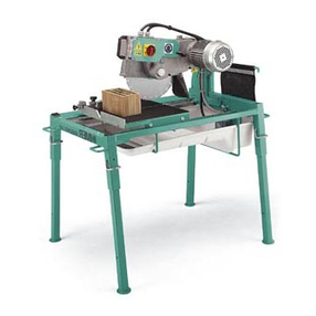
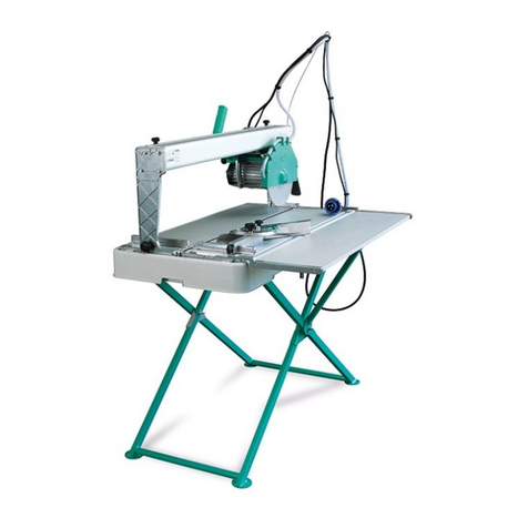
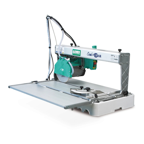
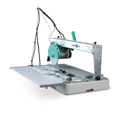
IMER Combi 200 Installation and operation manual

&20%,
(1188072 - 230V 50Hz) / (1188074 - 110V 50Hz)
manuale uso manutenzione (1 - 5)
manuel utilisation entretien (6 - 10)
Operating,maintenance, manual (11 - 15)
Handbuch für Bedienung, Wartung (16 - 20)
manual de uso, mantenimiento (21 - 25)
ricambi - pieces de rechange - spare parts - ersatzteile – recambios (26)
,0(5,17(51$7,21$/6S$
53036 POGGIBONSI (SIENA) Loc. SALCETO
,7$/,$
tel.: 0577 983300 - fax: 0577 983304
&RG5

COMBI 200: Operating and Maintenance Manual
___________________________________________________________________________________________________________________
11
*HQHUDOLQIRUPDWLRQ
,QWURGXFWLRQ
Dear Customer, congratulations on your purchase: the
&20%,
tile/stone
cutter is ideal for cutting tiles, thresholds and every kind of slab or fired tile.
This
86($1'0$,17(1$1&(
manual must be kept by the
6,7(0$1$*(5
within the building site, so it is always available for consultation. The manual is
to be considered part of the machine and must be kept for future reference
(EN292/2) for the whole machine life. If it is damaged or mislaid, a new copy
can be requested from the manufacturer. To guarantee the safety of the
operator, the safety of machine functioning and a long life for the machine, the
instructions in the manual must be respected, together with the safety and work
accident prevention regulations as per current legislation. Suitably safe
equipment must be used (safety shoes, gloves as per
'35,WDOLDQ'HFUHH
'35DQG'/,WDOLDQ/DZ
).
When writing to or telephoning your Agent or
,0(5,17(51$7,21$/ 6S$
for any reason involving the machine, always supply the following details:
1. machine model
2. serial number
3. voltage and frequency
4. period of use - number of working hours
5. type of disk used
5HFRPPHQGDWLRQVIRUDVVLVWDQFH
When compiling this manual, we kept in due consideration all the adjustment
and service operations which are part of normal maintenance.
We recommend that no repairs or operations are carried out which are not
indicated in this manual.
All operations which require parts to be dismantled must only be carried out by
qualified personnel.
,QWURGXFWLRQWRXVH
Before beginning machining with the tile/stone cutter, read this instructions
manual carefully to understand the machine, its uses and any possible counter-
indications.
The machine must be used exclusively for the uses hereby specified, use it as
recommended in this manual and do not try to tamper with it or force it, or to
use it for purposes not mentioned.
,0(5 ,17(51$7,21$/ 6S$
declines all responsibility in the case of non
observance of the laws which regulate the use of such equipment, in particular:
improper use, power supply anomalies, neglect of maintenance, unauthorised
modifications, partial or total non observance of the instructions contained in
this manual.
,W LV IRUELGGHQ WR FDUU\ RXW PRGLILFDWLRQV RI DQ\ NLQG RQ WKH
PDFKLQHVPHWDOVWUXFWXUHRUHOHFWULFDOV\VWHP
,GHQWLILFDWLRQ
The machine is marked by the captions punched on the metal plate on the
upper part of the machine (Fig.1.1-A).
'(6&5,37,212)&$37,216381&+('217+(0(7$/3/$7(
Type Machine model
No. Serial number
Year Year of manufacture
Volt Electrical voltage in Volts
Hz Electrical frequency in Hz
Kg Weight
Amp. Electrical absorption in Amps
rpm Number of revs. per minute of the disk
kW Nominal power
External diameter of disk
Disk hole diameter
$
Fig.1.1
Fig.1.2
'HVFULSWLRQ
&20%,
(Fig.1.2) is a small tile/stone cutter designed and manufactured by
IMER INTERNATIONAL
Spa
for cutting tiles, ceramics and stone in general.
The fundamental qualities of the machine are accuracy, reliability and lightness
which combine to make it a unique machine.
0DWHULDOVZKLFKFDQEHFXW
The machine can cut the following materials: ceramic tiles and stone in general
with the dimensions specified in section 1.6.1.
0DWHULDOVZKLFKFDQQRWEHFXW
The machine can only cut the materials mentioned in section 1.5.1. Using the
machine with other materials is forbidden.
♦In any case, before carrying out machining different from those
envisaged by the manufacturer or machining of materials different
from those for which the machine was manufactured, we
recommend that you contact
,0(5,17(51$7,21$/6S$
8VH RI WKH PDFKLQH ZLWK SDUW GLPHQVLRQV EH\RQG WKRVH IRU
ZKLFKWKH PDFKLQHZDV PDQXIDFWXUHGLV DEVROXWHO\IRUELGGHQ
DQGGDQJHURXVIRUWKHRSHUDWRU
7HFKQLFDOFKDUDFWHULVWLFV
6WDQGDUG&20%,FKDUDFWHULVWLFV
7(&+1,&$/'$7$
'LDPHWHURIWKHGLDPRQGGUHVVHGGLVN
mm 200
'LDPRQGGUHVVHGGLVNKROH
mm 25.4
&XWWLQJVXUIDFHGLPHQVLRQV
mm 650x420x20
8QLWVL]HOHQJWK[ZLGWK[KHLJKW
mm 775x520x360
8QLWVL]HIRUWUDQVSRUW
mm 805x530x370
0DFKLQHZHLJKWQHW
Kg 24
:HLJKWIRUWUDQVSRUWJURVV
Kg 27
&XWWLQJOHQJWKVS PP
&XWWLQJOHQJWKVS PP
mm 430
430
0D[LPXPFXWWLQJGHSWK
0D[LPXPFXWWLQJGHSWK
mm 40
20
:DWHUSXPSFDSDFLW\ /
11
7DQNFDSDFLW\ /
23

COMBI 200: Operating and Maintenance Manual
____________________________________________________________________________________________________________________
12
7(&+1,&$/'$7$
9ROWDJH
V230 110
)UHTXHQF\
Hz 50 50
0RWRUSRZHU
kW 0.37 0.37
0RWRUVSHHG
rpm 2830 2800
'LDPRQGGUHVVHGGLVNVSHHG
rpm 2830 2800
$EVRUEHGFXUUHQW
A2 4
'HVLJQVWDQGDUGV
&20%,,0(5
was designed and manufactured by applying the following
standards:
,(&(1(1'35
&RQVXOWLQJWKLVPDQXDO
The following is a description of the various types of symbol which will be seen
when reading this manual.
1RWHVV\PERO
♦
The notes highlight information which is particularly useful for correct machine
functioning.
6DIHW\ZDUQLQJV\PERO
∆
Failure to observe the safety warnings may lead to injury, both for the operator
and other persons.
'DQJHUVLJQDOV\PERO
The danger signal indicates situations of special danger where the operator
risks serious injuries.
5HIHUWRLOOXVWUDWLRQV
When the text refers to an illustration, for example: " ... (Fig.
&
) ...", refer to
part
&
in figure number
Some illustrations are included in the context,
while others are annexed.
The
&((8523($1&21)250,7<PDUN
confirms that the machine has
been designed according to and complies with European Community
requirements and regulated by precise Legal Standards. (DIR. 89/392/EEC -
91/368/EEC)
*HQHUDOVDIHW\ZDUQLQJV
Remember that this machine has been manufactured to offer, as well as better
performance, maximum safety: however, it is the operator who must guarantee
this safety, by taking the necessary precautions in all work phases. The
operator is advised to:
(QVXUHWKDWWKHHDUWKLQJXQLWLVVXLWDEOH
2QO\ZRUNZLWKDOOWKHJXDUGVLQSODFHDQGZRUNLQJFRUUHFWO\
.HHSWKHPDFKLQH FOHDQWKHJHQHUDOFOHDQLQJ RIWKHPDFKLQH
DQG LWV ZRUN VXUIDFHV LQ SDUWLFXODU LV DQ LPSRUWDQW VDIHW\
IDFWRU
6WRS WKH PDFKLQH FRPSOHWHO\ EHIRUH FOHDQLQJ LW RU EHIRUH
UHPRYLQJ DQ\ JXDUG IRU PDLQWHQDQFH RU UHPRYDO RI DQ\
FRPSRQHQW WXUQ WKH PDLQV VZLWFK WR ]HUR DQG GLVFRQQHFW
WKHSOXJ,IWKHPDFKLQHLVFOHDQHGZLWKZDWHUMHWVGRQRWVSUD\
ZDWHUGLUHFWO\RQWKHSRZHUVXSSO\XQLWRUHOHFWULFDOPRWRU
5HPRYH ULQJV ZDWFKHV EUDFHOHWV DQG WLHV H[SHULHQFH KDV
VKRZQ WKDW WKHVH DQG RWKHU REMHFWV FDQ OHDG WR DFFLGHQWV ,Q
DGGLWLRQ PDNH VXUHVOHHYHV DUH FORVHG WLJKWO\ RQ WKH ZULVWV
NHHSKDLUWLHGEDFNDQGXVHUREXVWIRRWZHDU
'RQRWPDFKLQHSLHFHVZKLFKDUHEH\RQGWKHVL]HVXLWDEOHIRU
WKHFKDUDFWHULVWLFVUHFRPPHQGHGE\WKHPDFKLQHPDQXIDFWXUHU
6HHSRLQW
7LJKWHQVFUHZVEROWVDQGULQJQXWVIRUHDFKLQVWUXPHQWWRWKH
WRUTXH HQYLVDJHG ZLWKRXW H[FHHGLQJ WKH QRUPDO YDOXHV DQG
ZLWKRXWXVLQJOHYHUVRUKLWWLQJWKHVSDQQHUV
$OZD\V XVH WKH SHUVRQDO SURWHFWLRQV DFFLGHQW SUHYHQWLRQ
JODVVHV ZKLFK FRQIRUP ZLWK VWDQGDUGV VXLWDEO\ VL]HG
FXVWRPLVHG JORYHV HDU PXIIV RU HDUSOXJV DQG KDLU QHWV LI
QHFHVVDU\
8VH WKH RULJLQDO WRROV UHFRPPHQGHG E\ WKH PDQXIDFWXUHU WR
HQVXUHPD[LPXPPDFKLQHSHUIRUPDQFH
$OZD\VNHHSWKHKDQGVIDUIURPWKHPDFKLQLQJDUHDVZKHQWKH
PDFKLQHLVUXQQLQJ%HIRUHUHPRYLQJDQ\SDUWV QHDUWKHGLVN
VWRSWKHGLVNURWDWLQJE\SUHVVLQJWKHVWRSSXVKEXWWRQ
7KHLQVWUXFWLRQVFRQWDLQHGLQWKLVPDQXDODUHIRUWKHXVHUVRI
WKHPDFKLQHRSHUDWRUVPDLQWHQDQFHSHUVRQQHO
1HYHUXVHFUDFNHGRUGHIRUPHGFXWWLQJGLVNV
1HYHUXVHWKHGLVNVDWDVSHHGKLJKHUWKDQWKDWLQGLFDWHGE\WKH
PDQXIDFWXUHU
2QO\XVHFRQWLQXRXVFURZQGLVNVRIDW\SHVXLWDEOHIRU
WKHPDWHULDOWREHFXW
6DIHW\GHYLFHV
&20%,
was designed in line with safety standards established at a
European level.
The safety devices, as per machine directive
((&
were designed with
utmost importance given to the safety of the operator.
Safety and accessibility are combined perfectly in
&20%,
; the operator is
fully protected, without any risks.
*XDUGVDQGVDIHW\GHYLFHV
The machine is fitted with fixed guards secured with fixing screws and guards
which prevent access to the moving and dangerous parts. All the fixed guards,
covers and screens secured with screws have been designed to protect the
operators (maintenance personnel, technicians, etc.) from injuries caused by
electrical discharges and moving mechanical parts.
Therefore, there is no envisaged use of the machine where the guards have
been modified or removed from the positions which they have been designed
for.
∆
%HIRUH FDUU\LQJ RXW DQ\ PDFKLQH PDLQWHQDQFH RU UHSDLUV WKH
PDFKLQHPXVWEHWXUQHGRIIDWWKHPDLQVVZLWFKDQGWKHPDLQV
SOXJ PXVW EH GLVFRQQHFWHG VR WKDW QRERG\ FDQ WXUQ RQ WKH
PDFKLQHXVLQJWKHPDLQVVZLWFK
0DFKLQHLQVWDOODWLRQ
/LIWLQJDQGXQORDGLQJ
Given its small size and lightness (only 24 Kg), Combi 200 can be lifted and
unloaded manually by the operator using the handles on the container tank.
$OZD\VHPSW\WKHWDQNEHIRUHPRYLQJWKHPDFKLQH
3RVLWLRQLQJ
Put the machine in the most suitable position, bearing in mind the electrical
connections. The space required for use and maintenance is shown in the
diagram below (Fig.2.2).
♦When moving the machine on the site, always take care to secure
the head with the lever (Fig. 3.1-G) and lift the machine with the
handles on the tank (Fig. 2.2/A-A).
$OZD\V GLVFRQQHFW WKH SRZHU VXSSO\ SOXJ EHIRUH PRYLQJ WKH
PDFKLQH
Fig.2.2
The machine may be supplied on an optional support stand (code 118.76.00)
as shown below (Fig.3.1/I).
%
$
Fig.2.2/A
♦Make sure that the stand is positioned on the supports on the
bottom of the tank.
&RQQHFWLQJWKHPDFKLQHWRWKHPDLQVSRZHUVXSSO\
Check that the mains power supply unit to which the machine is connected has
an earth connection as envisaged by current standards, and that the socket is
operating correctly.

COMBI 200: Operating and Maintenance Manual
___________________________________________________________________________________________________________________
13
♦Remember that there must be an overload protection upstream of
the mains power supply unit which can guarantee the safety of all
the conductors from short circuiting and overload.
(QVXUHWKDWWKHHOHFWULFOLQHKDVDVXLWDEOHGLIIHUHQWLDORYHUORDG
VZLWFK 5&' *)&,86$ ,0(5 PD\ VXSSO\ GLIIHUHQWLDO
RYHUORDGVZLWFKNLWV
230V-50Hz code 1187628
110V-50Hz code 1187629
Note the power installed (see machine identification plate) to dimension the
section of cable for the electric wiring, considering a maximum current capacity
of 4
$PPð
for lengths no higher than
PHWHUVRU
2
$PPð
for lengths between
DQGPHWHUV
7KHPDFKLQHPXVWEHFRQQHFWHG
WRWKHHTXLSRWHQWLDOHDUWKXQLW
LQ WKH EXLOGLQJ VLWH 7KH FRQQHFWLRQ SRLQW LV WKH VFUHZ
LQGLFDWHGZLWKWKHOHWWHU%LQ ILJ$SRVLWLRQHGRQ WKHUHDU
DUPPDUNHGZLWKDSODWHDQGDQHDUWKV\PERO
∆
7KHVHFWLRQRIWKHHDUWKFDEOHZKLFKLV\HOORZJUHHQVKRXOGEH
WKH VDPH DV WKH VHFWLRQ RI WKH OLQH FRQGXFWRUV RU DW OHDVW
FRQIRUPZLWKFXUUHQWOHJLVODWLRQDQGWHFKQLFDOVWDQGDUGVLQWKH
FRXQWU\LQZKLFKWKHPDFKLQHLVXVHG
∆
%HIRUH PDNLQJ WKH FRQQHFWLRQ FKHFN WKDW WKH PDLQV YROWDJH
DQGIUHTXHQF\FRUUHVSRQGWRWKHPDFKLQHVSHFLILFDWLRQV6HH
PDFKLQHLGHQWLILFDWLRQSODWH
∆
7KHSRZHUVXSSO\OLQHVLQWKHZRUNDUHDPXVWEHSRVLWLRQHGWR
HQVXUH WKDW WKH\ DUH QRW GDPDJHG DQG WKDW ZDWHU GRHV QRW
SHQHWUDWHWKHFROOHFWRUV 2QO\XVH FROOHFWRUVDQG DWWDFKPHQWV
ILWWHGZLWKZDWHUMHWSURWHFWLRQV 'RQRWSODFHWKH PDFKLQHRQ
WKHSRZHUVXSSO\OLQHV6XLWDEOHSURWHFWLRQPXVWEHDGRSWHG
∆
'R QRW XVH D WHPSRUDU\ PDFKLQH FRQQHFWLRQ WKH RSHUDWLRQ
PXVWEHFDUULHGRXWE\VSHFLDOLVHGSHUVRQQHO(QVXUHWKDWWKH
DWWDFKPHQWIRUWKHSRZHUVXSSO\FDEOHLQ WKHSOXJVZLWFKXQLW
KRXVLQJLVVWDEOH
∆
7KHZRUNDUHD PXVWUHVSHFW DFFLGHQWSUHYHQWLRQ DQGVHFXULW\
GHYLFHVWDQGDUGV
0DLQUHTXLUHPHQWVRIWKHHOHFWULFDOFDELQHWV
The motor is driven by pressing the push-button on the handle (Fig.3.3/A).
0DLQUHTXLUHPHQWVRIWKHHOHFWULFDOPRWRUV
Electric motor
characteristics 230V-50Hz 110V-50Hz
Power (Kw) 0.37 0.37
Nominal voltage (V) 230 110
Frequency (Hz) 50 50
Number of poles 2 2
R.p.m. 2830 2800
Isolation class S6 S6
Protection grade IP55 IP55
Type of mechanical
casing 63 B14 63 B14
Capacitor (µF) 14(D.36x65) 43(D.36x90)
0DFKLQHQRLVHOHYHO
,QWURGXFWLRQ
Protection from machine noise (
/SD
symbol) in the workplace has been
designed to meet the requirements of
$UWFRPPDRI/HJDO'HFUHHQR
RI
.
3URORQJHG H[SRVXUH WR QRLVH DERYH
G%$
PD\ GDPDJH
KHDOWK,WLVWKHUHIRUHUHFRPPHQGHGWKDWDSSURSULDWHSURWHFWLRQ
PHDVXUHVHJHDUPXIIVSOXJVHWFDUHWDNHQ
1RLVHHPLVVLRQPHDVXUHPHQWDVSHU
,62
VWDQGDUG
0DFKLQLQJ
&HUDPLFVWLOHVVWRQHLQJHQHUDO
)XQFWLRQLQJFRQGLWLRQ
,62%,6
VWDQGDUGDQGUHODWLYHDSSHQGLFHV
1RLVHOHYHO G%PHDVXUHG
0DFKLQHXVH
*HQHUDOGHVFULSWLRQ
Once the machine installation has been completed, machining can begin.
&20%,
consists of a stainless steel cutting surface. The 0.37 kW motor
and the cutting head (work unit) are fitted on a steel bar tilted at 45° to ensure
high cutting precision. The tile/stone cutter is placed on a tank, in plastic shock-
proof material, which contains water. The tank can be easily removed for
cleaning. There is a cooling pump immersed in the tank under the work table
which supplies the water jet for cooling the cutting disk.
&20%,
can be used for 90 degree vertical cutting and 45 degree tilted
cutting.
For vertical cutting, the pieces must have a maximum length of 430 mm and a
maximum thickness of 40 mm. For 45 degree tilted cutting, the pieces must
have a maximum length of 430 mm and a maximum thickness of 20 mm.
*
)
' &
%
(
$ +
,
Fig.3.1
The machine consists of a mobile cutting part (Fig.3.1-A), a fixed machine
support frame (Fig.3.1-B), a disk cooling tank (Fig.3.1-C) and an adjustment
unit (Fig.3.1-E).
The machine is fitted with protection devices to guarantee maximum functioning
safety (Fig.3.1-D).
)XQFWLRQLQJ
&20%,
functions as follows:
1. The piece to be machined is placed against the fence (Fig. 3.3 -E)
of the work surface with the required angle using the protractor
(Fig.3.1-E);
2. Select the cutting angle, vertical (Fig.3.1) or tilted at 45° (Fig.3.3); to
move the operating head to the fence, simply release the securing
knob (Fig.3.1-F) (Fig.3.2-A) for the operating head angle setting,
then secure the clamping knob again;
A
B
Fig.3.2
3. Turn the clamping knob for the operating head angle setting
(Fig.3.1-G);
4. Start up the machine using the maintained push-button near the
handle (Fig.3.3-A).
♦Make sure the tank is full of water during operations.
5. Press the piece against the table by hand
♦Apply a suitable pressure for the piece to be cut so that the motor is
not overloaded (motor under normal operating conditions
6. Move the operating unit and begin the cut; if the motor stops due to
overloading, retract the disk from the workpiece and allow the motor
to reach working speed before re-starting the cut.
The cut must be made near the fences on the work table.
♦If the 45° and 90° cuts are incorrect, adjust the screws on the two
arms (Fig. 3.3.-F).

COMBI 200: Operating and Maintenance Manual
____________________________________________________________________________________________________________________
14
'
%
$
)
&
(
Fig.3.3
2SHUDWLQJXQLW
The operating unit consists of the following:
1. A sliding unit guided by wheels on bearings (Fig.3.3-B and Fig.3.1-
A);
2. An electric motor (Fig.3.3-C);
3. A cutting unit consisting of a cutting disk (Fig.3.1-D);
4. A maintained push-button (Fig.3.3-A);
5. A cutting disk guard (Fig.3.1-H);
6. A handle (Fig.3.3-D);
7. An operating head clamping knob (Fig.3.1-F);
8. A safety knob (Fig.3.1-G);
0DLQWHQDQFH
,QWURGXFWLRQ
The normal operations for ordinary maintenance can be carried out by non
specialised personnel provided they observe the safety indications listed in the
previous and following paragraphs.
0DFKLQHFOHDQLQJ
The machine must
RQO\
be cleaned when the machine is at a standstill.
7KHSRZHUVXSSO\VZLWFKHVPXVWEHWXUQHGWRWKH
SRVLWLRQ
DQGWKHSOXJVGLVFRQQHFWHGIURPWKHPDLQVSRZHUVXSSO\
♦Do not used compressed air: this would send dust and residuals
into the most inaccessible corners of the machine.
♦Check that the cooling liquid nozzles are not blocked.
♦We recommend that the cooling water in the tank is changed every
day.
♦Do not use detergents or lubricants which may harm the materials of
which the machine is made.
'LVSRVDORIZDVWHPDWHULDOV
To dispose of the waste materials produced by the machine, current legislation
must be observed.
5HSDLUV
Repairs of the electrical systems must only be carried out by specialised
personnel. The spare parts to be used for mechanical repairs must be original
,0(5,17(51$7,21$/6SD
parts and they should not be modified in any way.
No further maintenance is required for the special structure of
&20%,
.
Check that the plug and plug-switch unit contacts are not damaged. If they are
oxidised, clean them immediately.
&OHDQLQJWKHWDQN
Clean the tank every time that sediment forms on the bottom, or at least once a
day. Failure to clean the tank could create problems for the immersion pump
which circulates water for cooling the cutting disk. To clean the tank, remove it
from the machine, secure the head, take it by the arms and wash it down with
direct water jets (this operation prevents direct contact of the electric parts and
the water jets), then clean it by hand with cloths or brushes.
♦Pay attention to the cable when replacing the machine on the tank.
♦Pay attention to the pump when releasing the machine and placing
it on the table.
5HSODFLQJWKHPRWRU
If you have to dismantle the electric motor, take care when re-fitting it on the
fixing plate.
∆
5HILW WKH HOHFWULFPRWRU XVLQJ WKHVDPH EROWV FRG
7DE$DQGZDVKHUVFRG7DE$VRWKDWEROWV
ZLWKWKHLQFRUUHFWGLPHQVLRQVGRQRWGDPDJHWKHPRWRU
5HSODFHPHQWRIWKHGLVN
The diamond-dressed disk is manufactured in special material for cutting the
materials described above and must be cooled with water during the work
phase.
To replace the disk, the following procedure must be followed:
1. Secure the axial slide of the operating head with the lever.
2. Dismantle the front guard.
3. Loosen the securing nut by turning it in a clockwise direction (left
hand thread), using a 10 mm spanner.
4. Remove the disk by first moving it and then tilting it slightly to extract
it from its housing.
♦When removing the disk, ensure that the cooling water jet nozzle is
not bent.
5. Insert the new disk, by carrying out the operations described in point
4 in reverse order, paying particular attention to the rotation direction
of the disk.
6. Secure the disk nut correctly by turning it in an anti-clockwise
direction (left hand thread), ensuring that there is a torque of 1.8
Kgf.m
$WWHQWLRQZKHQUHDVVHPEOLQJWKHGLVNIODQJHFKHFNWKDWWKHUH
DUHQRIRUHLJQERGLHVEHWZHHQWKHWLJKWHQLQJIODQJHDQGWKH
GLVN:KHQFOHDQLQJWKHIODQJHGRQRWXVHWRROVZKLFKPD\
DOWHUWKHVKDSHRIWKHIODQJH
([WUDRUGLQDU\PDLQWHQDQFH
After a work period of approximately one year, check that the operating unit is
stable; if not, carry out the following operations to stabilise it:
1. Release the two nuts (Fig.4.1-A);
2. Press down on the operating unit (near the plate)
3. First push the right wheel in a diagonal direction towards the inside
$
$
$
Fig.4.1
4. Secure the wheel nut by pressing it.
5. Do the same with the left wheel.

COMBI 200: Operating and Maintenance Manual
___________________________________________________________________________________________________________________
15
$SSHQGL[
The appendix contains the diagrams for the various units present in the
machine and the reference drawings. This section also contains the
documentation for the components installed in the machine and referred to in
the manual.
:LULQJGLDJUDPV
For wiring, the operator must consult the diagrams below
,
S1 Control switch
C1 Capacitor
X1 Disk motor connector
PE Overload line conductor
N Neutral line conductor
L1 Phase line conductor
M1 Disk motor
M2 Pump motor Fig.5.1
3UREOHPVFDXVHVVROXWLRQV
:$51,1*$OOWKHPDLQWHQDQFHRSHUDWLRQVPXVWEHFDUULHGRXWZKHQWKHPDFKLQHKDVEHHQVWRSSHGE\WXUQLQJWKHVHOHFWRUWR³´DQG
GLVFRQQHFWLQJWKHSRZHUVXSSO\
3UREOHP &DXVH 6ROXWLRQ
When the start switch is pressed, the motor does
not start −No mains voltage.
−The plug and socket are not connected
properly.
−The power supply cable is disconnected
from the cabinet.
−An electric wire inside the motor terminal
board is disconnected.
−An electric wire inside the cabinet is
disconnected.
−The mains switch is faulty.
−Check the mains.
−Reset the correct connection.
−Replace the cable.
−Contact an electrician for assistance.
−Contact an electrician for assistance.
−Change the switch.
No cooling water for the disk. −Consult machine cleaning, section 4.2 ,and tank cleaning, section 4.5
The disk does not cut. −Incorrect disk rotation direction.
−Worn disk.
−Dismantle the disk and reposition it in the
direction indicated on the disk label.
−Fit a new disk.

COMBI 200: ricambi - pieces de rechange - spare parts - ersatzteile - recambios
___________________________________________________________________________________________________________________
27
Fig.7.1/A

COMBI 200: ricambi - pieces de rechange - spare parts - ersatzteile - recambios
____________________________________________________________________________________________________________________
28
Fig.7.1/B
7$9$.
5LI &RGLFH , ) *% ' ( 1RWH
1 2223570 DADO ECROU NUT MUTTER TUERCA 5588 M8
2 2224140 RONDELLA RONDELLE WASHER BEILAGSCHEIBE ARANDELA Ø 8x18
3 3206312 FASCETTA COLLIER CLAMP SCHELLE ABRAZADERA
4 2223920 DADO ECROU NUT MUTTER TUERCA 7474 M10
5 3206385 PROTEZIONE
QUADRO PROTECTEUR
TABLEAU CABINET GUARD SCHUTZ
SCHALTTAFEL PROTECCIÓN CUADRO
6 3207397 RUOTA ROUE WHEEL RAD RUEDA
7 3207394 DISTANZIALE ENTRETOISE SPACER DISTANZSTÜCK ESPESOR
8 3206744 PIASTRA SUP.
MOTORE PLAQUE SUP.
MOTEUR MOTOR SUPPORT
PLATE MOTORTRAGPLATTE PLANCHA SUP. MOTOR
9 2222516 VITE VIS SCREW SCHRAUBE TORNILLO 5931 M8X70
10 3207118 BLOCCAGGIO
BRACCIO BLOCAGE BRAS ARM CLAMP ARMVERRIEGELUNG DISP. BLOQUEO BRAZO
11 3207393 DISTANZIALE ENTRETOISE SPACER DISTANZSTÜCK ESPESOR
12 1193848 DISCO CERAMICO DISQUE CÉRAMIQUE TILE DISK KERAMIKSCHEIBE DISCO CERÁMICO
13 3206409 CARTER CARTER GUARD SCHUTZHAUBE CUBIERTA
14 2222021 VITE VIS SCREW SCHRAUBE TORNILLO TEFR M6x16
15 1222013 VITE VIS SCREW SCHRAUBE TORNILLO 5737 M6X45
16 3208759 VITE SINISTRA VIS GAUCHE SCREW SCHRAUBE MIT
LINKSGEWINDE TORNILLO IZQUIERDO 5739 M6X20SX
17 3206377 FLANGIA BRIDE FLANGE FLANSCH BRIDA
18 3206376 FLANGIA BRIDE FLANGE FLANSCH BRIDA
19 3205941 TUBO
REFRIGERAZIONE TUBE
REFROIDISSEMENT COOLING TUBE KÜHLWASSERSCHLAU
CH TUBO REFRIGERACIÓN
20 3205985 PARASPRUZZI PARES-EAU SPLASH GUARD SPRITZSCHUTZ PROTECC. CONTRA
SALPICADURAS
21 2224340 ROSETTA RONDELLE WASHER BEILAGSCHEIBE ARANDELA 6592 Ø10x20
22 2223655 DADO M 10 BASSO ECROU M 10 BAS M 10 LOW NUT MUTTER M 10 FLACH TUERCA M 10 BAJA 5589 M10
23 2225749 FASCETTA
AUTOSERRANTE COLLIER À AUTO-
SERRAGE SELF-LOCKING CLAMP SELBSTSICHERNDE
SCHELLE ABRAZADERA CON
AUTOBLOQUEO
24 3206231 PROTEZIONE
PARASPRUZZI PARES-EAU SPLASH GUARD SPRITZSCHUTZ PROTECCIÓN CONTRA
SALPICADURAS
25 2224530 ROSETTA RONDELLE WASHER BEILAGSCHEIBE ARANDELA 6592ø6x12.5
26 2223924 DADO M 6 ECROU M 6 M 6 NUT MUTTER M6 TUERCA M 6 AUTOBL. M 6
27 3207076 ROSETTA NYLON RONDELLE NYLON NYLON WASHER NYLONRING ARANDELA NYLON NYLON Ø10,5X21X1
28 2224531 ROSETTA RONDELLE WASHER BEILAGSCHEIBE ARANDELA 6593 Ø6x18
29 3206085 VOLANTINO VOLANT HANDWHEEL HANDRAD VOLANTE
30 2222540 VITI VIS SCREWS SCHRAUBEN TORNILLOS 5931 M6X20
32 3205972 GUIDA DI
SCORRIMENTO GUIDE DE
COULISSEMENT SLIDING GUIDE GLEITFÜHRUNG GUÍA DE
DESLIZAMIENTO
43 3206121 BATTUTA DESTRA BUTÉE DROITE RIGHT FENCE RECHTER ANSCHLAG TOPE DERECHO
44 3206122 BATTUTA SINISTRA BUTÉE GAUCHE LEFT FENCE LINKER ANSCHLAG TOPE IZQUIERDO

COMBI 200: ricambi - pieces de rechange - spare parts - ersatzteile - recambios
___________________________________________________________________________________________________________________
29
7$9$.
46 3207058 PIANO DESTRO TABLE DROITE RIGHT TABLE RECHTER TISCH SUPERFICIE DERECHA
47 3207059 PIANO SINISTRO TABLE GAUCHE LEFT TABLE LINKER TISCH SUPERFICIE
IZQUIERDA
48 3206164 PERNO PIVOT PIN ZAPFEN PERNO
49 3205943 TAPPO BOUCHON PLUG VERSCHLUSS TAPÓN
50 3207075 GRANO VIS SANS TÊTE SET SCREW GEWINDESTIFT PRISIONERO 5923 M8X20
51 3207074 GRANO VIS SANS TÊTE SET SCREW GEWINDESTIFT PRISIONERO 5923 M8X40
53 2222146 VITE VIS SCREW SCHRAUBE TORNILLO 5739 M10x30
54 2225142 GRANO VIS SANS TÊTE SET SCREW GEWINDESTIFT PRISIONERO 5927 M6X10
55 2288825 ADESIVO PRESA
TERRA ADHÉSIF PRISE
TERRE EARTH SOCKET
ADHESIVE LABEL SCHILD ERDE ADHESIVO TOMA
TIERRA
57 2223923 DADO
AUTOBLOCCANTE ECROU DE SÉCURITÉ SELF-LOCKING NUT SELBSTSICHERNDE
MUTTER TUERCA CON
AUTOBLOQUEO M.8
58 2292365 TUBO ANTIGELO TUBE ANTIGEL ANTI-FREEZE TUBE SCHLAUCH
FROSTSCHUTZ TUBO ANTIHIELO
59 3206580 BRACCIO BRAS ARM ARM BRAZO
60 3207055 SUPP. ANT. SUPPORT AVANT FRONT SUPPORT LAGER VORN SOPORTE DELANTERO
61 3207052 SUPP. POST. SUPPORT ARRIÈRE REAR SUPPORT LAGER HINTEN SOPORTE TRASERO
62 3208449 SUPP. POMP. SUPPORT POMPE PUMP SUPPORT LAGER PUMPE SOPORTE BOMBA
64 2222004 VITE VIS SCREW SCHRAUBE TORNILLO M8x35
65 2225748 FASCETTA COLLIER CLAMP SCHELLE ABRAZADERA
66 3205934 VASCA CUVE TANK WANNE DEPÓSITO
67 3207116 ADESIVO BATTUTA
SINISTRA ADHÉSIF BUTÉE
GAUCHE LEFT FENCE
ADHESIVE LABEL SCHILD LINKER
ANSCHLAG ADHESIVO TOPE
IZQUIERDO
68 3207117 ADESIVO BATTUTA
DESTRA ADHÉSIF BUTÉE
DROITE RIGHT FENCE
ADHESIVE LABEL SCHILD RECHTER
ANSCHLAG ADHESIVO TOPE
DERECHO
69 2241570 CHIAVE CLÉ SPANNER SCHLÜSSEL LLAVE
70 3205980 GONIOMETRO GONIOMÈTRE PROTRACTOR GONIOMETER GONIÓMETRO
71 3206384 CARTER RUOTE CARTER ROUES WHEEL GUARD SCHUTZABDECKUNG
RAD CÁRTER RUEDAS
72 3206381 BLOC. TEST. BLOCAGE TÊTE HEAD CLAMP VERR. KOPFT. DISP. DE BLOQUEO
CABEZAL
73 3205988 SUP. GONIOMETRO SUPPORT
GONIOMÈTRE PROTRACTOR
SUPPORT HALTERUNG
GONIOMETER SOP. GONIÓMETRO
74 3204945 CUSCINETTO ROULEMENT BEARING LAGER RODAMIENTO 608-2RS1
75 3207073 ANELLO BAGUE RING RING ANILLO
77 3213097 ANELLO BAGUE RING RING ANILLO
79 2216277 GUARNIZIONE IN
GOMMA GARNITURE EN
CAOUTCHOUC RUBBER SEAL GUMMIDICHTUNG JUNTA DE GOMA
81 3207129 DADO ECROU NUT MUTTER TUERCA 5589 M8
82 3213111 SCATOLA FKL 63-71 BOÎTIER FKL 63-71 FKL 63-71 BOX DOSE FKL 63-71 CAJA FKL 63-71
83 3203540 GUARNIZIONE
MORSETTIERA GARNITURE BORNIER TERMINAL BOARD
SEAL DICHTUNG
KLEMMENLEISTE JUNTA REGLETA DE
CONEX.
84 3213114 PIASTRA AL PORTA
MICRO PLAQUE AIUMINIUM
PORTE-MICRO MICROSWITCH
HOLDER ALUMINIUM
PLATE
AL-PLATTE
MIKROHALTERUNG PLANCHA AL
SUJETAMICRO
85 3213115 MICROINTERRUTTOR
E 1NO MICRO-
INTERRUPTEUR 1 NO 1NO MICROSWITCH MIKROSCHALTER 1
NO MICROINTERRUPTOR
1NO
86 3213116 PULSANTE NEUTRO
BIANCO BOUTON NEUTRE
BLANC WHITE NEUTRAL
PUSH-BUTTON NEUTRALER
DRUCKTASTER WEISS PULSADOR NEUTRO
BLANCO
87 1283910 PRESSACAVO SERRE-FILS CABLE CLAMP KABELKLEMME APRIETACABLE PG 9
88 3203822 FERMACAVO BC CAVALIER CÂBLE BC BC CABLE CLAMP KABELHALTER BC APRIETACABLE BC
89 3203120 FERMACONDENSATO
RE CAVALIER
CONDENSATEUR CAPACITOR CLAMP KONDENSATORSCHEL
LE SUJETACONDENSADO
R
90 1283982 DADO PER
PRESSACAVO ECROU POUR SERRE-
FILS CABLE CLAMP NUT MUTTER FÜR
KABELKLEMME TUERCA PARA
APRIETACABLE PG 9
91 3207243 VOLANTINO VOLANT HANDWHEEL HANDRAD VOLANTE
100 3207978 GONIOMETRO COMPL. GONIOMÈTRE GONIOMETER WINKELMESSER GONIÓMETRO
7$99+=$.
5LI &RGLFH , ) *% ' ( 1RWH
31 3213117 CONDENSATORE CONDENSATEUR CAPACITOR KONDENSATOR CONDENSADOR MF 14 V450
52 3206411 TARGHETTA DATI
TECNICI PLAQUE CAR.
TECHNIQUES TECHNICAL DATA
PLATE LEISTUNGSSCHILD PLACA DATOS
TÉCNICOS
56 3208443 POMPA POMPE PUMP PUMPE BOMBA
63 3206071 SPINA FICHE PLUG STECKER CLAVIJA
76 3213090 MOTORE COMPLETO MOTEUR COMPLET COMPLETE MOTOR MOTOR MOTOR COMPLETO KW 0,37
78 3213108 QUADRO ELETTRICO TABLEAU
ÉLECTRIQUE ELECTRIC PANEL SCHALTTAFEL CUADRO ELÉCTRICO
80 3207128 TARGHETTA ADESIVA PLAQUE ADHÉSIVE ADHESIVE PLATE KLEBESCHILD PLACA ADHESIVA
7$99+=$.
5LI &RGLFH , ) *% ' ( 1RWH
31 3213119 CONDENSATORE CONDENSATEUR CAPACITOR KONDESATOR CONDENSADOR MF 43 V250
52 3206412 TARGHETTA DATI
TECNICI PLAQUE CAR.
TECHNIQUES TECHNICAL DATA
PLATE LEISTUNGSSCHILD PLACA DATOS
TÉCNICOS
56 3206270 POMPA POMPE PUMP PUMPE BOMBA
63 3204782 SPINA FICHE PLUG STECKER CLAVIJA
76 3213091 MOTORE COMPLETO MOTEUR COMPLET COMPLETE MOTOR MOTOR MOTOR COMPLETO KW 0,37
78 3213109 QUADRO ELETTRICO TABLEAU
ÉLECTRIQUE ELECTRIC PANEL SCHALTTAFEL CUADRO ELÉCTRICO
80 3207130 TARGHETTA ADESIVA PLAQUE ADHÉSIVE ADHESIVE PLATE KLEBESCHILD PLACA ADHESIVA
Other manuals for Combi 200
1
This manual suits for next models
2
Other IMER Saw manuals
