D
DD
D
Streifennagler
Streifennagler Streifennagler
Streifennagler 3506
35063506
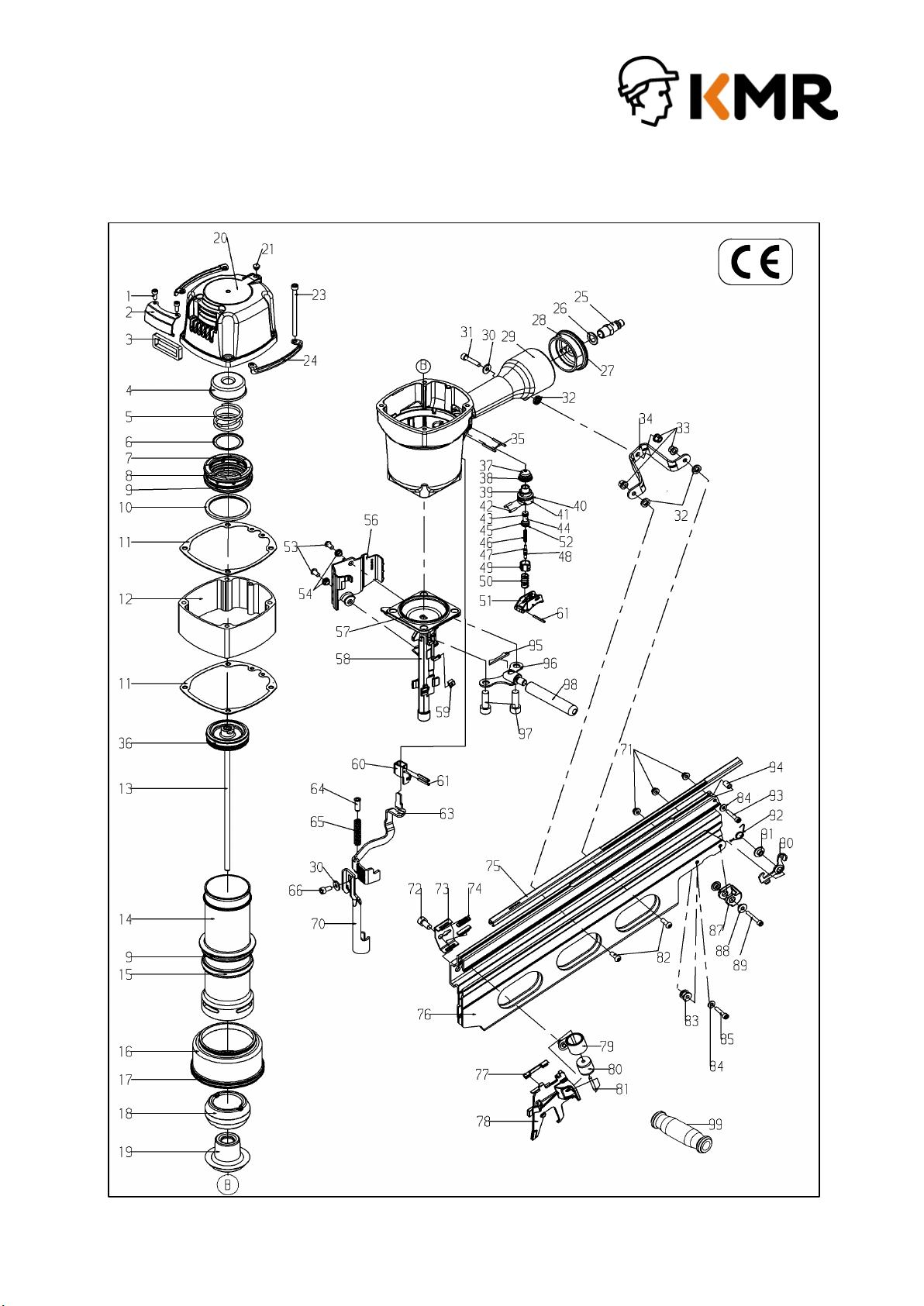
3506
Technische Daten
[1]
[1][1]
[1]Abmessungen: L = 568 H = 538 B=145 mm
[2]
[2][2]
[2]Gewicht: 6,9 kg.
[3]
[3][3]
[3]Zulässiger Luftdruck: 8 bar,
[4]
[4][4]
[4]empfohlener Betriebsdruck: 5 - 8 bar.
[5]
[5][5]
[5]Luftverbrauch pro Eintreibvorgang bei 4,9 bar: 7 l freie Luft.
[6]
[6][6]
[6]Eintreibgegenstand:
Kunststoffgebundene Nagelstreifen 3,8 – 4,6
Längen von 100 - 160 mm.
[7]
[7][7]
[7]A-bewerteter Einzelereignis-
Schalleistungspegel L Wa, 1s = 105,7 dB
[8]
[8][8]
[8]A-bewerteter Einzelereignis-
Emission Schalldruckpegel
am Arbeitsplatz L pA, 1s = 92,7 dB
[9]
[9][9]
[9] Vibrationswert 5,41 m/s2
[10]
[10] [10]
[10] Magazinart: Oberlader
[11]
[11][11]
[11] Ladekapazität: min 2 Streifen
[12]
[12] [12]
[12] Luftanschluß: 9 bis 10 mm Nennweite
Diese Ersatzteilliste/Servicehinweise bildet mit dem beiliegenden
Diese Ersatzteilliste/Servicehinweise bildet mit dem beiliegenden Diese Ersatzteilliste/Servicehinweise bildet mit dem beiliegenden
Diese Ersatzteilliste/Servicehinweise bildet mit dem beiliegenden
Benutzer
BenutzerBenutzer
Benutzer-
--
-
Handbuch die Betriebsanleitung. Bitte vor Inbetriebnahme
Handbuch die Betriebsanleitung. Bitte vor Inbetriebnahme Handbuch die Betriebsanleitung. Bitte vor Inbetriebnahme
Handbuch die Betriebsanleitung. Bitte vor Inbetriebnahme
aufmerksam lesen und Sicherheitshinweise beachten.
aufmerksam lesen und Sicherheitshinweise beachten.aufmerksam lesen und Sicherheitshinweise beachten.
aufmerksam lesen und Sicherheitshinweise beachten.
Achtung
AchtungAchtung
Achtung:
Gerät von der Pneumatik-Druckquelle trennen, Magazin en
Befestigung der Kappe 14509932 muß mit einem Drehschrauber erfolgen,
bei dem das Drehmoment auf 14 Nm eingestellt ist.
Austausch des Treibers und des Kolbens
Austausch des Treibers und des KolbensAustausch des Treibers und des Kolbens
Austausch des Treibers und des Kolbens
Die Schrauben 14509927
und das Hauptventil 14508867 mit der Kappe
14509932 herausd
rehen. Mit dem Ersatztreiber, der von unten in den
Treiberkanal eingeführt wird, die Kolben-Treiber-Einheit 14509237
oben aus dem Naglergehäuse hinausdrücken und komplett austauschen.
Vor dem Wiedereinsetzen Kolben-O-Ring einfetten mit O-Ring-
13301706.
Auswechseln des Puffers und des Zylinders
Auswechseln des Puffers und des ZylindersAuswechseln des Puffers und des Zylinders
Auswechseln des Puffers und des Zylinders
Kappe und Kolben-
Treibereinheit wie oben beschrieben demontieren.
Dann den Nagler umdrehen und kräftig auf eine plane Holzplatte schlagen.
Durch die Erschütterung lösen sich Zylinder und Puffer und lassen si
leicht dem Gehäuse entnehmen. Defekte Teile ersetzen und leicht gefettet
(O-Ring-Fett 13301706) einsetzen.
GB
GBGB
GB
Strip Nailer Type
Strip Nailer Type Strip Nailer Type
Strip Nailer Type 3506
35063506
3506
This Spare parts list/service instructions and the enclosed Operator's
This Spare parts list/service instructions and the enclosed Operator's This Spare parts list/service instructions and the enclosed Operator's
This Spare parts list/service instructions and the enclosed Operator's
Manual constitute the Operating instruction
Manual constitute the Operating instructionManual constitute the Operating instruction
Manual constitute the Operating instruction
s. Before using read both
s. Before using read both s. Before using read both
s. Before using read both
and strictly observe safety instructions.
and strictly observe safety instructions.and strictly observe safety instructions.
and strictly observe safety instructions.
In the German part of the spare part list the technical data are marked
with a code in [ ]
[ ] [ ]
[ ] brackets.
Important:
Important: Important:
Important:
Disconnect the machine from the compressed air supply, empty
magazine. The cover 14509932 should only be fastened with a mechanical
screwdriver – torque set at 8Nm.
Replacement of the driver and piston
Replacement of the driver and piston Replacement of the driver and piston
Replacement of the driver and piston
Unscrew the screw 14509927
and the main valve 14508867 with the cap
14509932. Push the piston-driver unit 14509237
upwards out of the riveter
housing with the aid of the replacement driver which is inserted from
below into the driver channel, and exchange completely. Before replacing,
grease o-ring with o-ring grease 13301706.
Replacement of the buffer and the cylinder:
Replacement of the buffer and the cylinder: Replacement of the buffer and the cylinder:
Replacement of the buffer and the cylinder:
Dismount the cover and piston-
driver unit as described above. Then turn
the riveter upside down and rap it strongly against a level wooden board.
The cylinder and buffer will be loosened by the jolt and can
removed from the housing. Replace faulty parts and re-in
greased o-ring
(o-ring grease 13301706).
F
FF
F
Cloueur à pointes en bandes type
Cloueur à pointes en bandes type Cloueur à pointes en bandes type
Cloueur à pointes en bandes type 3506
35063506
3506
Cette Nomenclature des pièces détachées et Instructions de montage
Cette Nomenclature des pièces détachées et Instructions de montage Cette Nomenclature des pièces détachées et Instructions de montage
Cette Nomenclature des pièces détachées et Instructions de montage
et le Manuel de l'ut
et le Manuel de l'utet le Manuel de l'ut
et le Manuel de l'ut
ilisateur font partie du Mode d'Emploi. Avant
ilisateur font partie du Mode d'Emploi. Avant ilisateur font partie du Mode d'Emploi. Avant
ilisateur font partie du Mode d'Emploi. Avant
utilisation veuillez les lire attentivement.
utilisation veuillez les lire attentivement.utilisation veuillez les lire attentivement.
utilisation veuillez les lire attentivement.
Dans la partie allemande de la liste des piéces de rechange les données
techniques sont marquées par [ ] (veuillez voir aussi le manuel de
l'utilisateur.
Attention
AttentionAttention
Attention
:
::
:
Débrancher l’appareil de la source d'alimentation en air comprimé, vider le
magasin. Le cache 14509932 doit être fixé à l’aide d’une visseuse rotative
réglée sur un couple de 14 Nm.
Retirer la vis 14509927 et la soupape principale 14508867 avec le cach
14509932 en les dévissant. Introduire par en bas le chassoir de
remplacement dans le canal afin de faire ressortir par le haut du boîtier
l’ensemble constitué du piston et du chassoir 14509237
complètement. Avant de remettre en place les
pièces, lubrifier le joint
torique du piston avec de la graisse pour joint torique 13301706.
Remplacement du butoir et du cylindre
Remplacement du butoir et du cylindreRemplacement du butoir et du cylindre
Remplacement du butoir et du cylindre
Démonter le cache et l’ensemble constitué du piston et du chassoir
comme décrit ci-dessus. Puis retourner la cloueuse et la
fortement contre une planche de bois plane. Le cylindre et le butoir se
détachent sous le choc et peuvent ainsi être retirés facilement du
boîtier. Remplacer les pièces défectueuses. Lubrifier légèrement les
pièces avant de les remettre en place (gr
aisse pour joints toriques
13301706).
E
EE
E
Clavadora para clavos en tira Tipo
Clavadora para clavos en tira Tipo Clavadora para clavos en tira Tipo
Clavadora para clavos en tira Tipo 3506
35063506
3506
Esta Lista de piezas e instrucciones de mantenimiento son partes
Esta Lista de piezas e instrucciones de mantenimiento son partes Esta Lista de piezas e instrucciones de mantenimiento son partes
Esta Lista de piezas e instrucciones de mantenimiento son partes -
--
-
junto con las Instrucciones para el operario
junto con las Instrucciones para el operario junto con las Instrucciones para el operario
junto con las Instrucciones para el operario -
--
-
de las Normas de
de las Normas de de las Normas de
de las Normas de
Trabajo. Antes del utilizo
Trabajo. Antes del utilizo Trabajo. Antes del utilizo
Trabajo. Antes del utilizo
deben leerse detenidamente dichas
deben leerse detenidamente dichas deben leerse detenidamente dichas
deben leerse detenidamente dichas
instrucciones y atender las instrucciones de seguridad.
instrucciones y atender las instrucciones de seguridad. instrucciones y atender las instrucciones de seguridad.
instrucciones y atender las instrucciones de seguridad.
En la parte alemana de la lista de repuestos figuran datos técnicos bajo
cifras características. [ ]
[ ][ ]
[ ] (Véase también el manual de usuario.)
Atención
AtenciónAtención
Atención
Desconectar el
aparato del suministro de aire comprimido, vaciar el
cargador. Se debe fijar la cubierta con ayuda de un destornillador con un
par fijado a 14 Nm.
Sustitución del percutor y del pistón
Sustitución del percutor y del pistónSustitución del percutor y del pistón
Sustitución del percutor y del pistón
Destornillar y sacar el tornillo 14509927 y la válvula principal 14508867
con la cubierta 14509932. Sacar de la carcasa de la clavadora la unidad
pistón-percutor 14509237 introduciendo el percutor de repuesto en el
canal del percutor por debajo y presionando hacia arriba, y sustituir la
unidad completa. Lubricar la junta tórica del pistón con grasa de junta
tórica 13301706 antes de volver a montar el conjunto.
Sustitución del tope y del cilindro
Sustitución del tope y del cilindroSustitución del tope y del cilindro
Sustitución del tope y del cilindro
Desmontar la cubierta y la unidad pistón-
percutor como se describe
arriba. Girar la clavadora y golpearla vigorosamente contra
superficie de madera. El cilindro y el tope se aflojan con las sacudidas
con lo que se pueden extraer fácilmente de la carcasa. Sustituir las
piezas defectuosas y colocar las nuevas ligeramente engrasadas (grasa
de junta tórica 13301706).
I
II
I
Fissatr
FissatrFissatr
Fissatrice per chiodi in stecca Tipo
ice per chiodi in stecca Tipo ice per chiodi in stecca Tipo
ice per chiodi in stecca Tipo 3506
35063506
3506
La Lista ricambi/istruzioni di manutenzione e l'allegato Manuale per
La Lista ricambi/istruzioni di manutenzione e l'allegato Manuale per La Lista ricambi/istruzioni di manutenzione e l'allegato Manuale per
La Lista ricambi/istruzioni di manutenzione e l'allegato Manuale per
l'utilizzatore costituiscono l'istruzioni per l'uso. Leggeteli
l'utilizzatore costituiscono l'istruzioni per l'uso. Leggeteli l'utilizzatore costituiscono l'istruzioni per l'uso. Leggeteli
l'utilizzatore costituiscono l'istruzioni per l'uso. Leggeteli
attentamente prima di utilizzare le fissatrici e rispettare
attentamente prima di utilizzare le fissatrici e rispettare attentamente prima di utilizzare le fissatrici e rispettare
attentamente prima di utilizzare le fissatrici e rispettare
assolutamente le norme di si
assolutamente le norme di siassolutamente le norme di si
assolutamente le norme di sicurezza riportate.
curezza riportate. curezza riportate.
curezza riportate.
Nella parte tedesca della distinta pezzi di ricambio, i dati tecnici sono
evidenziati tra parentesi quadre [ ]
[ ][ ]
[ ]
. (cfr. anche il manuale per
l'operatore)
Attenzione
AttenzioneAttenzione
Attenzione
Scollegare il compressore dallo strumento, svuotare il caricatore. Il
f
issaggio della testata 14509932 deve essere effettuato con un
avvitatore, con il quale regolare il momento torcente a 14 Nm.
Sostituzione del punzone e del pistone
Sostituzione del punzone e del pistoneSostituzione del punzone e del pistone
Sostituzione del punzone e del pistone
Svitare la vite 14509927
e la valvola principale 14508867 con la testata
14509932. Con il p
unzone di ricambio, che deve essere introdotto dal
lato inferiore del relativo condotto, spingere verso l’alto il gruppo
punzone-pistone 14509237
in modo tale da farlo fuoriuscire, quindi
sostituirlo completamente. Prima di rimontarlo, ingrassare l’anello O-
ring del pistone con l’apposito grasso 13301706.
Sostituzione dello stantuffo e del cilindro
Sostituzione dello stantuffo e del cilindroSostituzione dello stantuffo e del cilindro
Sostituzione dello stantuffo e del cilindro
Smontare la testata e il gruppo punzone-
precedentemente descritto. Quindi, ruotare la chiodatrice e colpire
vigorosamente una superficie piana di l
egno. Il colpo farà in modo che il
cilindro e lo stantuffo si sblocchino e che li si possa facilmente
rimuovere dal corpo dell’attrezzo. Sostituire le parti difettose e
ingrassare leggermente (grasso per anelli O-ring 13301706)
NL
NLNL
NL
Stripapparaat
Stripapparaat Stripapparaat
Stripapparaat 3506
35063506
3506
Dez
DezDez
Deze Onderdelenlijst en service
e Onderdelenlijst en servicee Onderdelenlijst en service
e Onderdelenlijst en service-
--
-
instructie vormt één geheel met
instructie vormt één geheel met instructie vormt één geheel met
instructie vormt één geheel met
bijgaand instructie
bijgaand instructiebijgaand instructie
bijgaand instructie-
--
-boekje en de gebruiksaanwijzing.
boekje en de gebruiksaanwijzing. boekje en de gebruiksaanwijzing.
boekje en de gebruiksaanwijzing.
Lees het
Lees het Lees het
Lees het