manuals.online logo
Brands
  1. Home
  2. •
  3. Brands
  4. •
  5. Lamp
  6. •
  7. Door Opening System
  8. •
  9. Lamp FD30-F User manual

Lamp FD30-F User manual

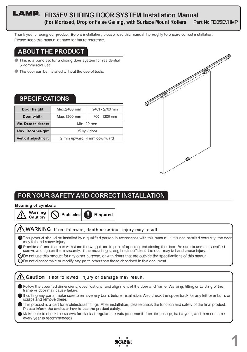
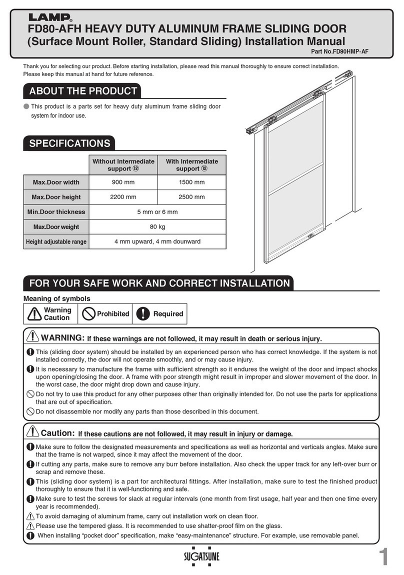
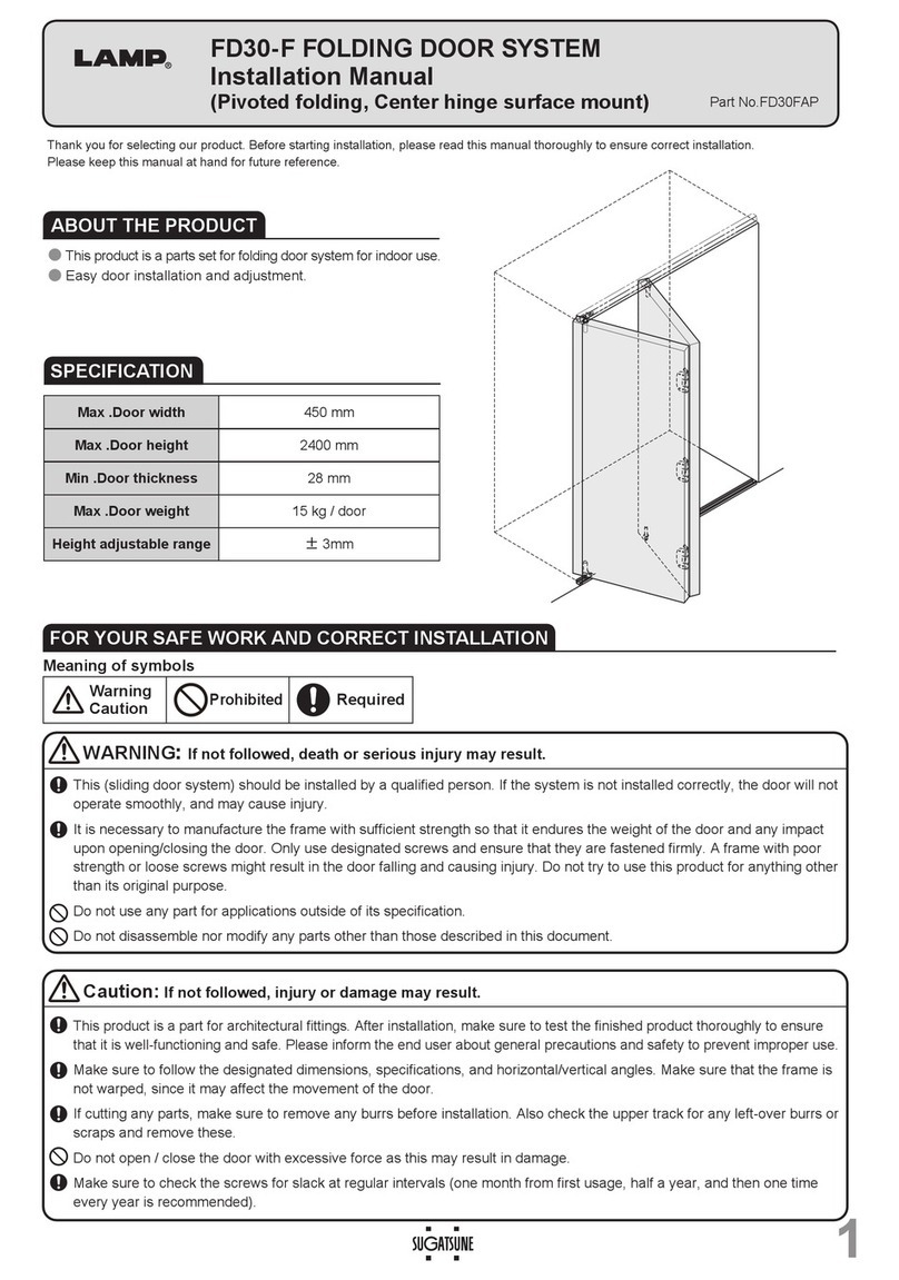
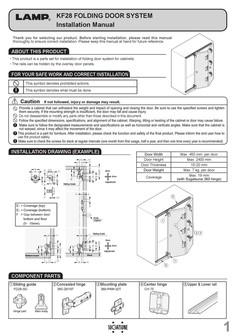
■SPECIFICATIONS
Max. Door width
Min. Door thickness
Max. Door height Max. Door weight
Vertical adjustment
FD30-F 450mm 30mm 2400mm 15kg/door ±4mm
3
7
6
6
1
8
9
5
5
Handle(Optional)
FD30-F CEILING MOUNT, FOLDING DOOR SYSTEM
Installation Manual
(Slidable folding, Center hinge Door edge recessed mount)
Thank you very much for selecting FD30-F FOLDING DOOR SYSTEM.
Before starting installation, please read this installation manual
thoroughly to install the door correctly. Improper installation may result
in injury. To prevent such accident, please follow instructions described
in this manual. After installing the door, leave this manual to the owner
so that the owner is able to use this manual to check the door any time.
The door system will be upgraded/improved without announcement, for
change in dimensions or specifications, please confirm with delivered
door system parts.
■FOR YOUR SAFETY WORK AND OPERATION
symbol denotes “warning” and ”caution” during work or operation. symbol
denotes the item which should be avoided to keep safety. symbol denotes
item which should be followed to avoid injury. If this item is not followed, injury
may be resulted.
This folding door system should be installed by experienced person who has
correct knowledge. If the system is not installed correctly, the door will not operate
smoothly, and/or may cause injury.
Do not try to use this product for any other purposes other than originally intended
for. Do not disassemble the components for any modifications. Do not use the
system for applications that are out of specification. Any improper use might result
in accident or injury. We do not take any responsibility for any damage, accident or
injury occurring from an improper use, application or wrong installation.
Avoid opening/closing the door with excessive force. Such operation may cause
trouble.
It is necessary to manufacture the frame with sufficient strength to endure the
weight of door and impact shocks upon opening/closing the door. A frame with
poor strength might result in improper and slower movement of the door. In the
worst case, door might drop down causing injury.
Warning: If this warning is not followed, it may
result in injury or damage.
IMPORTANT:
・
This manual is prepared to describe the installation methods
considered most safe and effective to set up and install the sliding
door system. The installation procedures or methods can be changed
to meet your working conditions or environments.
・
In this manual, the dimensions are not considering margin of error
or deformation of material. Therefore, please carry out each process
such as cutting, taking care of deformation or other changes.
Part No.
FD30URP
①②③④⑤⑥⑦ ⑧ ⑨
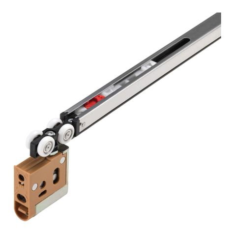
Upper roller
Cover cap Guide pin Pivot insert Jig Upper stopper Bottom stopper
Center hinge Rail
(Surface mount)
Rail
(Recessed mount)
Guide rail
(Surface mount)
Guide rail
(Recessed mount)
2
-door reversible separator
Select either type Select either type
2221223
4-door reversible separator
Select either type Select either type
2441226
As optional parts, upper roller cap are offered. Please refer Page 4 for detail.
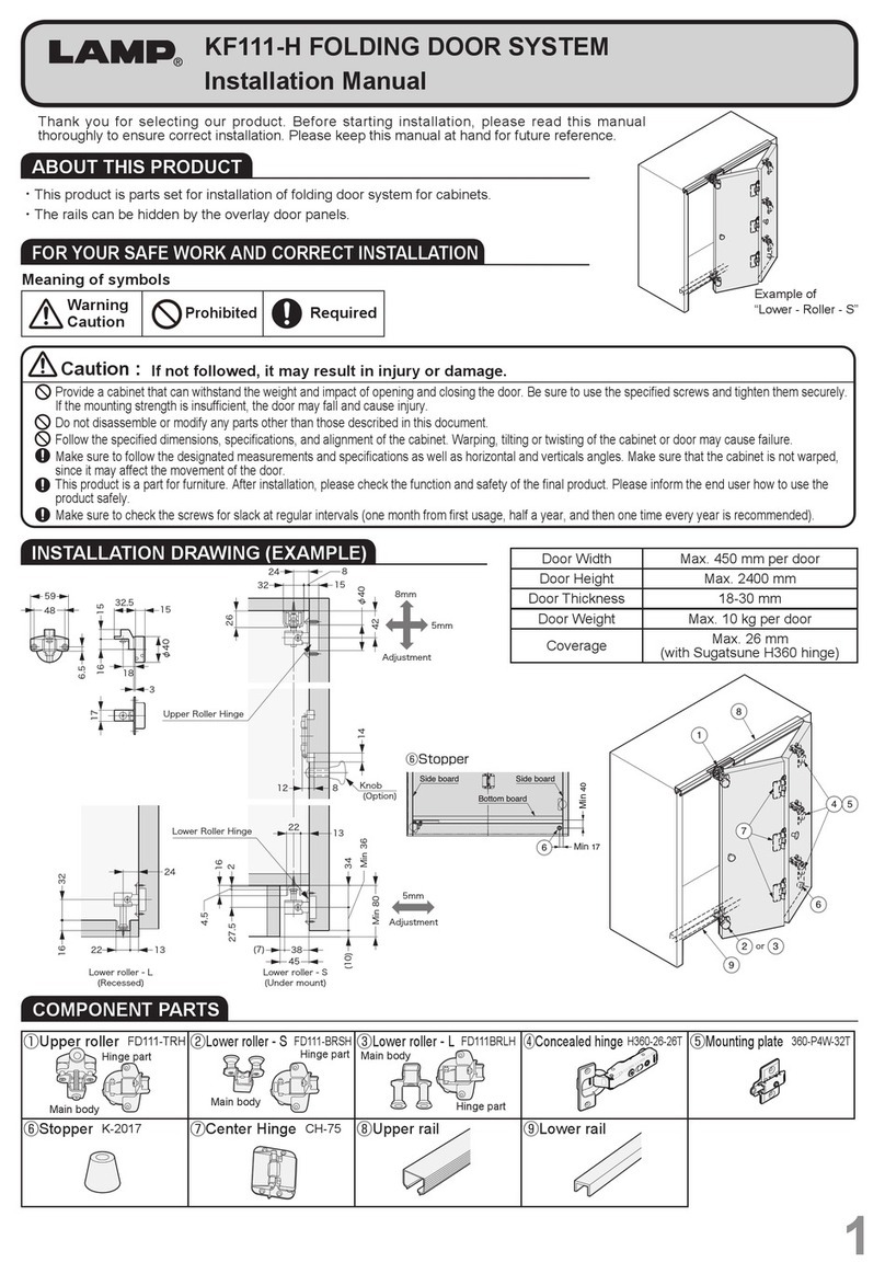
■COMPONENT PARTS
収納部
収納部
収納部
収納部
収納部
収納部
右
上
下
左
右
上
下
左
np20d13.eps
np20d13.eps
nh03d23.eps
nh03d23.eps
■INSTALLATION DRAWING(EXAMPLE)
2
右
上
下
左右
上
下
左
32
20
1.4
10.5
10
19.5
3232
0.8
1.3
4
2021
20
11
(150) (150)
32
CE
7±4(Vertical adjustment range)
1.2
D=32
±2
When operating door:
Approx.105
18.5 +0
-0.5
Upper Rail
(Surface mount)
Upper Rail
(Recessed)
Move door side Pivot side
1
2
1
55
2
7
33
66
8
9
φ22
φ12
338 +2
-0
+2.5
-0
+0
-0.3
32
16
R8
47
47.5
±0.5
ファイル名:naord13.eps
sugatodigi
   ↓
  koide内
Upper door
Bottom door
25 35 18
40
上ローラー 加工図 センターヒンジ 加工図センターヒンジ 加工図
50+0.5
-0
7+0.3
-0
1616
58
25
R8
7.5
naord06.eps
8
Process dimension for hinge
■
Door processing dimension
■Minimum Dimension between Frame and Door
Door opening (when 40mm door thickness, 450mm door width)
Door
thickness
C = Gap
E = Gap
Door width
300
Door width
350
Door width
400
Door width
450
30 4.0 3.5 3.0 2.7 2.4
35 5.2 4.3 3.7 3.3 3.0
40 6.5 5.2 4.5 4.0 3.6
No.
Name Dimensional drawing Specification
⑦
Center hinge
(Door edge)
(Angle adjustable,
w/Detent stop)
Single Part order code
:250-017-167
Part No.
:
FD30-CHK
●
Material
 
Zinc alloy
●
Finish
 
Dark brown
●
Attached screw
Tapping screw
3.5
×
25
⑧
Rail
(surface mount)
●
Material Aluminum alloy
●
Finish
Anodized aluminum
(Silver or amber)
●
Length 910mm,1820mm,
2000mm,2730mm,
3000mm,3640mm,
4000mm
●
Set screw is not attached.
(recommended screw is tapping
screw of 3.5x20)
Rail
(recessed mount)
⑨
Bottom guide rail
(surface mount)
●
Finish
Anodized aluminum
(Silver or amber)
●
Length 910mm,1820mm,
2730mm,3640mm
●
Attached screw
Tapping screw 3.5x16
Bottom guide rail
(recessed mount)
nh03d03.eps
No.
Name Dimensional drawing Specification
①
Upper Roller
(recessed)
Single Part order code
:250-017-135
Part No.
:
FD30-WRH
●
Material Zinc alloy/Polyacetal
●
Finish Colored Chromating
/Light brown
●
Attached screw
Tapping screw
3.5
×
30,3 screws
②
Cover cap Order code:250-017-138
Part No.:FD30-WRH-CP
●Material Polypropylene
●Finish Brown
③
Guide pin
Single Part order code
:250-017-164
Part No.
:
FD30-FGR
●
Material Polyamide/Steel
●
Finish Yellow Zinc Chromate/
Main and Roller part:Natural
④
Pivot insert Jig
ー
Single Part order code
:250-017-169
Part No.:FD30-FSJ
●
Material Polyvinyl chloride
⑤
Upper stopper
Single Part order code
:250-017-143
Part No.:FD30-FTST
●
Material Steel/Polyacetal
●
Finish Yellow Zinc Chromate/Dark brown
⑥
Bottom stopper
Single Part order code
:250-017-166
Part No.:FD30-FBKS
●
Material Polyacetal/Steel
●
Finish Colored Dark brown/Chromating
np20d13.eps
nh03d32.eps
右
上
下
左
22
φ16
39
30
45
16.6
16
47.5
右
上
下
左
nh03d02.eps
φ
15
φ20
φ10.6
φ12
8
32
41
0
〜
17
38.8
29.5 4.8
18
3
np20d14.eps
np20d26.eps
632.5
15.5
6.5
1
2
20
4.5
φ12
825
22
1.5
58
9
7.5
24
0.4
44
1.5
22
61
58
φ4.5φ7.8
CSK
1717
1.5
np20d50.eps
np20d12.eps
28
11
φ5φ7.8
CSK
np20d10.eps
20
24
10.5
1.4
φ5φ7.8
CSK
19.5
20
φ4.8 φ7.8 CSK
9.2
18.21.2
20
φ4.8

φ7.8 CSK

9.2
23
Hole pitch:300mm
Pitch:30mm
Hole pitch:300mm
Pitch:30mm
Hole pitch:300mm
Pitch:30mm
Hole pitch:300mm
Pitch:30mm
nh03d23.eps
2
12
46.8
15.8
nh03d24.eps
3
右
上
下
左
Pivot insert Jig
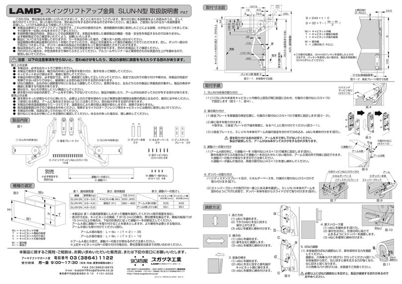
6. Installing guide pin
Install guide pin to door
bottom with striker. Be
careful not to damage the
plastic part of guide.
7. Installing center hinge
Confirm door position and hinge position.
Insert center hinge into processed area, and
fix with fix screws.
Upper roller
(casing)
5. Installing lower stopper
Assemble lower stopper (in
correct posture), and install
guide rail. Temporally fix it at
Pivot side.Temporally fix lower
stopper to the designated
position at Pivot side.
Guide pin
Remove any dirt or aluminum chips from the rail as they would damage the rollers and cause noise during operation.
1. Cutting the rail
Cut the rail applying a reinforcer to prevent
deformation of cut section.
2. Preparation before mounting parts
Pull up the lever of upper roller to separate main body
from casing. (When removing the door for adjustment
after finishing door installation, the door can be
removed by raising the lever.)
Loosen fix screws on upper and lower stoppers.
3. Installing casing
Firmly insert upper rollerr casing into the place
as shown, fix it with attached screws.
■ASSEMBLY
Confirmation
before assembly
・
Check that dimensions of frame, floor, door and rail are correct.
・
Check that frame and floor are not inclined.
・
Check that door is processed correctly.
・
Check that door is not warped.
・
Check that all parts are prepared.
PROCEDURE
1
PREPARATION AND INSTALLATION
1. Fixing door (Door bottom)
Insert convex of guide pin in guide rail groove.
2. Fixing door (Door upper)
Insert upper roller main unit into the casing
installed on door until click sound is heard.
Ensure that roller main unit is securely attached
to the casing.
PROCEDURE
2
HANGING DOOR
4. Assembly of parts
Assemble parts, in order of upper stopper,
upper roller, and upper stopper, taking
care for part direction.
右
上
下
左
右
上
下
左
Upper roller
(main unit)
Upper roller
(casing)
Lever
Bottom of door
(Pivot side)
Convex portion Guide rail
Lower stopper
Guide rail
Pivot side
Rail
Upper stopper
Lower stopper
右
上
下
左
右
上
下
左
右
上
下
左
Upper stopper
Upper roller
(main unit)
Upper stopper
Upper roller
(main unit)
Upper roller
(casing)
1.
Adjusting inclination of door
Loosen upper stopper and lower
stopper to make the door vertical.
Then, retighten screws.
右
上
下
左
nahrd04.eps
±2
Left-to-right
adjustment
screw
Vertical position
adjust screw
Clockwise =Raise
Counterclockwise=Lower
20
φ12
NP-23
移動扉側
2
20
φ12
NP-23
移動扉側
2
Fixing screws of
the
Upper
stopper
Fixing screws of
the
Lower
stopper
4. Adjustment of door angle
With Philips screwdriver, adjust the
screw on center hinge.
Adjustmentscrew:
Adjust with the door
folded.
Counterclockwise (2 turns MAX.)
Clockwise (1 turns MAX)
178˚
179˚
右
上
下
左
nahrd04.eps
右回し=上がる
左回し=下がる
7±4
±4
2. Adjusting vertical position (±4mm)
Adjust vertical adjustment
screw on upper roller with
Philips screw driver.
3.
Left-to-right adjustment (±2mm)
With Philips screwdriver, adjust
the position of upper roller.
Do not rotate adjustment screw
exceeding adjust range. It may
cause damage.
ISO9001(Japan Offices and Sugatsune America) and ISO14001(Chiba Production division and Logistics center), certified.
2014.01 PRINTEDINJAPAN 0764-1 
Move the door slowly. When door is not moved smoothly, adjustment may be needed to correct door position.
Adjust upper roller to obtain door smooth operation
PROCEDURE
3
Confirmation of door movement and adjustment
Final confirmation…Confirm that all screws are securely tightened. And, confirm that all screws are used
without mistake.
PERIODICAL INSPECTION
・Clean inside of rail.
・Check upper space and lower space of the door. If necessary, correct the space.
Trouble Check Solution
Abnormal noise during
operation
Check if door touches adjacent parts. Provide necessary space between door and adjacent objects.
Check inside of upper rail for foreign matter or
aluminum dust.
Remove dust or foreign matter.
Check rail rollers for aluminum dust. Remove the rail and pull out the roller. Then, clean the roller.
Check for loose screws retaining the upper rail. Tighten the screw.
Heavy door operation Door bottom touches the floor. Confirm that screws on the rails are not loosened. And, adjust door height. Adjust
the clearance between door bottom and floor to 10mm.
(20mm:Surface mount type guide rail)
Check if door touches adjacent parts. Correct door position to avoid contact to other objects.
Adjust position of upper and bottom stopper.
Check if door is warped. Use the door without warp.
Door does not move. Check rail retaining screws for looseness. Roller touches the screw.
Retighten screws to free the roller.
Door starts to move. Check if the upper rail is set horizontally. Using a level gauge, reset upper rail horizontally.
■TROUBLESHOOTING

This manual suits for next models

1

Other Lamp Door Opening System manuals

Lamp FD50-H User manual

Lamp

Lamp FD50-H User manual

Lamp AZ-GD231 User manual

Lamp

Lamp AZ-GD231 User manual

Lamp KF28 User manual

Lamp

Lamp KF28 User manual

Lamp LDD-S User manual

Lamp

Lamp LDD-S User manual

Lamp FD35EV User manual

Lamp

Lamp FD35EV User manual

Lamp FM150PRO User manual

Lamp

Lamp FM150PRO User manual

Lamp FD50-H User manual

Lamp

Lamp FD50-H User manual

Lamp HCZ-80 User manual

Lamp

Lamp HCZ-80 User manual

Lamp AZ-AT230-HL Instruction Manual

Lamp

Lamp AZ-AT230-HL Instruction Manual

Lamp FD80-H User manual

Lamp

Lamp FD80-H User manual

Lamp FD30EX User manual

Lamp

Lamp FD30EX User manual

Lamp FD50-H User manual

Lamp

Lamp FD50-H User manual

Lamp FD50-H User manual

Lamp

Lamp FD50-H User manual

Lamp FD35EV User manual

Lamp

Lamp FD35EV User manual

Lamp XL-GC07D-CR User manual

Lamp

Lamp XL-GC07D-CR User manual

Lamp FD30EX User manual

Lamp

Lamp FD30EX User manual

Lamp HC-70 User manual

Lamp

Lamp HC-70 User manual

Lamp HDSN-30K User manual

Lamp

Lamp HDSN-30K User manual

Lamp SLUN-N User manual

Lamp

Lamp SLUN-N User manual

Lamp FD80-AFH User manual

Lamp

Lamp FD80-AFH User manual

Lamp HC-30L User manual

Lamp

Lamp HC-30L User manual

Lamp FD35EV User manual

Lamp

Lamp FD35EV User manual

Lamp MonoFlat FAD-5 User manual

Lamp

Lamp MonoFlat FAD-5 User manual

Lamp FD35EV User manual

Lamp

Lamp FD35EV User manual

Popular Door Opening System manuals by other brands

GEZE MSW sliding wall system Mounting and operating instructions

GEZE

GEZE MSW sliding wall system Mounting and operating instructions

Eco EFR III Assembly instruction

Eco

Eco EFR III Assembly instruction

GAL MOVFR installation instructions

GAL

GAL MOVFR installation instructions

JNF IN.15.702 installation manual

JNF

JNF IN.15.702 installation manual

SOMFY ROLLIXO RTS installation manual

SOMFY

SOMFY ROLLIXO RTS installation manual

Pujol Receptor REV Variocode Installation and adjustment instructions

Pujol

Pujol Receptor REV Variocode Installation and adjustment instructions

Manaras Opera-MH Installation instructions manual

Manaras

Manaras Opera-MH Installation instructions manual

GEZE ISM Boxer installation instructions

GEZE

GEZE ISM Boxer installation instructions

SECO-LARM SD-7175SGEX1Q manual

SECO-LARM

SECO-LARM SD-7175SGEX1Q manual

Dorma 900S Series installation instructions

Dorma

Dorma 900S Series installation instructions

Norton 8000 Series installation instructions

Norton

Norton 8000 Series installation instructions

Dormakaba TS 97 FLR-K XEA Mounting instructions

Dormakaba

Dormakaba TS 97 FLR-K XEA Mounting instructions

SECO-LARM Enforcer Access SD-962AR-36A manual

SECO-LARM

SECO-LARM Enforcer Access SD-962AR-36A manual

CornellCookson FS-150EP Series Installation instructions and operation manual

CornellCookson

CornellCookson FS-150EP Series Installation instructions and operation manual

Besam SW200i Installation and service manual

Besam

Besam SW200i Installation and service manual

Dorma 8916 FT manual

Dorma

Dorma 8916 FT manual

Assa Abloy Sargent Electroguard-59 80 Series Installation and wiring instructions

Assa Abloy

Assa Abloy Sargent Electroguard-59 80 Series Installation and wiring instructions

Von Duprin Allegion 3327A Series Service manual

Von Duprin

Von Duprin Allegion 3327A Series Service manual

manuals.online logo
manuals.online logoBrands
  • About & Mission
  • Contact us
  • Privacy Policy
  • Terms and Conditions

Copyright 2025 Manuals.Online. All Rights Reserved.