manuals.online logo
Brands
  1. Home
  2. •
  3. Brands
  4. •
  5. Lamp
  6. •
  7. Door Opening System
  8. •
  9. Lamp FD80-H User manual

Lamp FD80-H User manual

1
Part No.
FD80DHCMP
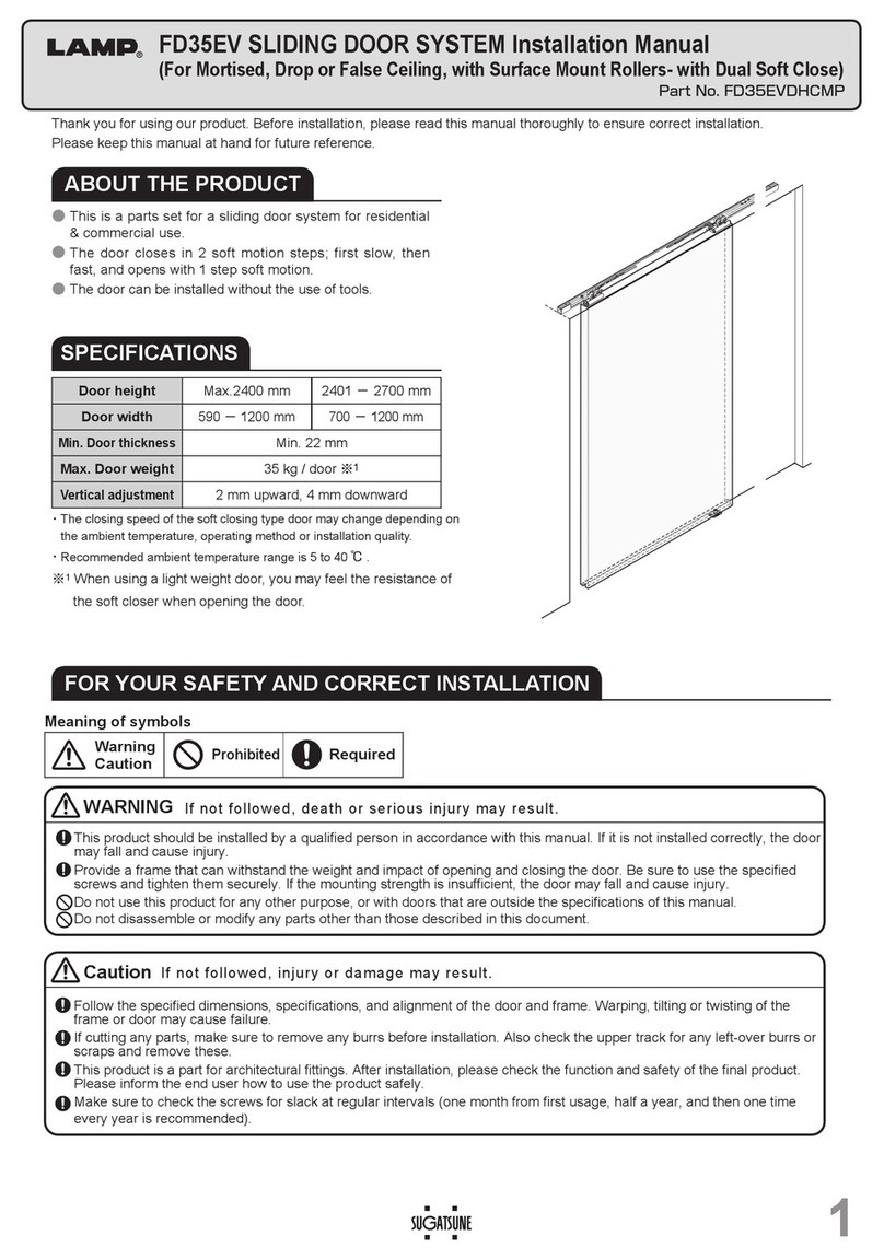
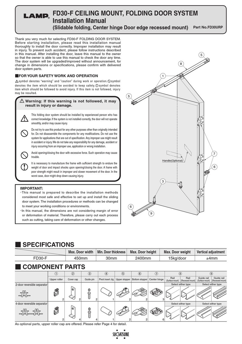
Thank you for selecting our product. Before starting installation, please read this manual thoroughly to ensure correct installation.
Please keep this manual at hand for future reference.
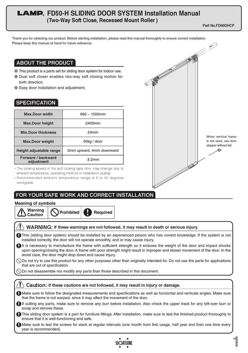
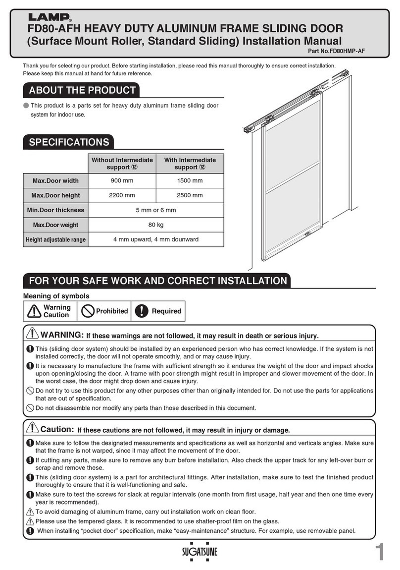
ABOUT THE PRODUCT
●This product is a parts set for heavy duty sliding door
system for indoor use.
●Built in soft closer enables two-way soft closing movement
for both direction.
SPECIFICATIONS
Door width 784 mm – 1500 mm
Max.Door height 2500 mm
Min.Door thickness 30 mm
Max.Door weight 80 kg
Height adjustable range 4 mm upward, 4 mm downward
FOR YOUR SAFE WORK AND CORRECT INSTALLATION
・
The closing speed of the soft closing type door may change due
to ambient temperature, operating method or installation quality.
・
Recommended ambient temperature range is 5 to 40 degrees
centigrade.
FD80-H SLIDING DOOR SYSTEM Installation Manual
(Two-Way Soft Close, Surface Mount Roller)
WARNING:

If these warnings are not followed, it may result in death or serious injury.
Caution:
If these cautions are not followed, it may result in injury or damage. 
This (sliding door system) should be installed by an experienced person who has correct knowledge. If the system is not
installed correctly, the door will not operate smoothly, and or may cause injury.
It is necessary to manufacture the frame with sufficient strength so it endures the weight of the door and impact shocks
upon opening/closing the door. A frame with poor strength might result in improper and slower movement of the door. In
the worst case, the door might drop down and cause injury.
Do not try to use this product for any other purposes other than originally intended for. Do not use the parts for applications
that are out of specification.
Do not disassemble nor modify any parts than those described in this document.
Make sure to follow the designated measurements and specifications as well as horizontal and verticals angles. Make sure
that the frame is not warped, since it may affect the movement of the door.
If cutting any parts, make sure to remove any burr before installation. Also check the upper track for any left-over burr or
scrap and remove these.
This (sliding door system) is a part for architectural fittings. After installation, make sure to test the finished product
thoroughly to ensure that it is well-functioning and safe.
Make sure to test the screws for slack at regular intervals (one month from first usage, half year and then one time every
year is recommended).
Prohibited
Warning
Caution Required
Meaning of symbols
2
INSTALLATION DRAWING (EXAMPLE)
INSTALLATION PROCEDURE (This manual explains assembly of single side sliding door system.)
COMPONENT PARTS
No. ①②③④⑤⑥
Name Two-way soft closer
(surface mount) Trigger Upper loller
(surface mount) Floor guide S Upper track
Door bottom guide
track
Item No. FD80-WRM-DSC FD80-WRM FD50-BG18 FD80-TRM series
FD30-HBRT1500SIL
Item
(Various sizes)
Hole pitch :250 mm
Pitch end :30 mm
1500mm
Hole pitch :250 mm
Pitch end :30 mm
Single sliding
1pc 2pcs 1pc 1pc 1pc 1pc
Double sliding
2pcs 4pcs 2pcs 2pcs 2pcs 2pcs
In line sliding
2pcs 4pcs 2pcs 2pcs 2pcs 2pcs
⑦
OPTIONAL
PARTS
No. ⑧⑨⑩⑪
Trigger mount jig Name
Stopper block (sold separately)
'RRUVWRSSHUÀRRU Floor guide L Spanner
FD80-TRJ
Item No. FD80-HSB FD30-HTKY FD50-BG32 FD30-FSP
Item
This is used in the upper
track. This is used when larger
space below the door is
required.
Accessory screw:
Pan head tapping screw
4×45・・・・・・ 4pcs
Accessory screw:
Pan head tapping screw
4×45・・・・・・ 4pcs
Accessory screw:
Pan head tapping screw
5×40
Accessory screw:
Bind head tapping screw
4×16・・・・・・ 5pcs
Accessory screw:
Bind head tapping screw
4×30・・・・・・ 3pcs
Accessory screw:
Bind head tapping screw
4×16・・・・・・・5pcs
Accessory screw:
Countersunk head tapping
screw 4×30(φ6head)
・
・
4pcs
Nominal designation 10,12
Door processdimension
INSTALLATION DIMENSIONS FOR TRIGGER 2

Please add the Margin DN to dimension for Trigger 2,
if you are using a protruding handle. Example shown
below.
DW
※3
[Margin DN=0 mm]
Installation dimension for
Trigger 2
※2
【ForDoubleslidingonly】
Example [Margin DN=70 mm]
DW-473+DN is the Installation
dimension for Trigger 2
1,000 527 597
1,100 627 697
1,200 727 797
1,300 827 897
1,400 927 997
1,500 1,027 1,097
Double Sliding
Single Sliding
Dimension DW: For detail, refer to Installation Drawing (Example)
1. Cutting Upper Track and Hole Processing
PREPARATION AND INSTALLATION
1
5 mm dia. Hole (2)
5 mm dia. Hole (2)
5.5 mm dia. Hole
263
DW-482
18 30
18
Caution
Remove any dirt or aluminum chips
from the track.
Trigger 1
Door end
when fully closed
Door end
when fully closed
Door end when fully closed
Trailing edge of door
Leading edge
of door
15
17
1
3
8(in track )
8
(in track)
4
65
272
DN Overlap
272
DW−473+DN※2
(See right table.)
DN+50
Door width DW Margin DN
DN+50
Overlap
272
272
604.5
18
80
25
DW−473※3
(See below table.)
Track pitch300
30
Margin DN Overlap
80
25
18
64
41 5
9
Door handle
(sold separately)
Door width DW
40
3420±4※1
Min:30
15
1710
28
16
Trigger mount hole 5 dia.
4×5.2×8.2Ellipse hole
(4 holes on upper track)
7
12
12
25
72
Trigger 1 Trigger 2
Trigger 1
Trigger 2
Trigger 2
Trigger 2
Trigger 1
DW−473+DN※2
(See right table.)
DW−473※3
(See right table.)
※1Height adjustable range : -4 mm to +4 mm.
3
HANGING DOOR AND ADJUSTMENT
2
Floor Guide(④or⑩)
2. Top Part
Insert the upper roller into the holder as shown in the drawing below.
※
Bind head tapping
screw 4×16
1.
Bottom Part
,QVHUWWKHÀRRUJXLGH6LQWKHJURRYH
and then hang the door in the bracket.
2. Installing Bracket
Remove Bracket and Holder from Upper roller.
Mount the Bracket with attached screws.
Tapping screw
4×16(not provided)
Correct set position
Trigger catcher
Correct set position
If the closer is installed without conformation,
it will cause the trouble such as no-sliding of door.
ϕ6
If the position is wrong, pull back the trigger catcher to
the correct position using 6mm diameter hard bar.
Incorrect set position
OK
272
Leading edge
Trailing edge
⑤Upper track
③Upper roller
①Two-way
soft closer
❶
❷
Door (tail end)
32
※
Pay attention on setting direction of the bracket.
Opening part of the bracket should face to outside direction.
3.
Installation of Door Bottom Guide Track
Fix door bottom guide track with the recommended
VFUHZV¿UPO\
⑥Door bottom guide
track(for dimensions, refer to
“INSTALLATION DRAWING”)
①Two-way
soft closer
③Upper roller
Leading edge
Trailing edge
Leading edge : The
leading edge of the
track has two 5 mm
dia. holes at 272 mm
position from the end.
Refer to “Installation Drawing
(Example)”
Floor Guide(④or⑩)
⑤Upper track
Upper roller
Bracket
80
25
80
6
72
110 25
121225
①、③screw
4×45
Outside
Outside
Bracket
Holder
Upper roller
Remove
&RQ¿UDWLRQ%HIRUH,QVWDOOLQJWKH7ZRZD\6RIW&ORVHU 5.
Assembly of Parts For Track
(1) Assemble the parts in order of ❶to ❷with care of direction.
(2) Tape around rollers and upper track to prevent drop of
inserted parts.
6. Mounting Upper Track
&RQ¿UPWKDWOHDGLQJHGJHRIWKHXSSHUWUDFN
is in same direction as the leading edge of
the door. Fix the upper track with attached
Screws 5×40.
7. Mounting Trigger
According to “Installation Drawing (Example)”,
install triggers with attached Screws 4×16D6.
8. Mounting Floor Guides
Install the floor guide so that it remains between
the leading and trailing edges of the door when it is
opened or closed.
3.
Remove the jig.
2.
Install trigger.
1.
Align trigger and
mounting jig with
mount hole.
②Trigger
Leading edge
②Trigger
Screw
4×30
(Φ6head)
Trigger mount hole
Trigger mounting jig
90°
Trigger
Mounting
screws
90° Out of the straight
Correct installation
Out of straight
Correct installation
272mm DW-473mm
4
SUGATSUNE KOGYO CO.,LTD  
Tokyo, JAPAN
Phone: +81 (0)3 3866 2260 E-mail:[email protected]
SUGATSUNE KOGYO (UK) LTD  
Reading, UK
Phone: +44 118 9272 955
 
E-mail:[email protected]
SUGATSUNE EUROPE GmbH  
Dusseldorf, GERMANY
Phone: +49 211 53812900
 
E-mail:[email protected]
SUGATSUNE SHANGHAI Co., LTD  
Shanghai, CHINA
Phone: +86 21 3632 1858  E-mail:[email protected]
Guangzhou, CHINA  
Phone: +86 20 6639 3552  E-mail:[email protected]
SUGATSUNE KOGYO INDIA PRIVATE LIMITED  
Mumbai, INDIA
Phone: +91 22 28314490/91 E-mail:[email protected]
SUGATSUNE AMERICA, INC  
California, USA
Phone: +1 310 329 6373 E-mail:[email protected]
Chicago, USA  
Phone: +1 312 461 1081
E-mail:[email protected].
SUGATSUNE CANADA, INC.  
Phone: +1 514 312 5267
E-mail:[email protected]
2017.10 0516-6
Trouble Check Point Remedy
Door stops during soft
closing &KHFNLIGRRUERWWRPFRQWDFWVZLWKÀRRU Confirm that
track
fixing screws are not loosened. Then, adjust door height
VXFKWKDWFOHDUDQFHEHWZHHQGRRUERWWRPDQGÀRRUEHFRPHVPP
No soft closing Check if door stops before door stopper. Close the door completely. This will reset the function.
Check if trigger is installed. Install the trigger to correct position.
Check if door is closed with excessive force. Do not close the door with excessive force. It prevents suitable function
causing trouble. Use normal operating force.
Abnormal noise during
operation Check if door contacts to other parts. Provide necessary space between door and adjacent objects.
Check inside of upper track for existence of foreign
matter such as aluminum dust. Remove dust or foreign matter.
Check track rollers for existence of dust or aluminum powder.
Remove the
track
and pull out the roller. Then, clean the roller.
Check for loosened screws retaining the upper
track.
Tighten the screw.
Heavy door operation Check if door contacts to other parts. Provide necessary space between door and adjacent objects.
Check if door is warped. Use the door without warp.
Door starts to move. Check
track
retaining screws for looseness. Tighten the screw.
Door does not move. Check the upper
track
if it is set horizontally. Using a level gauge, reset upper
track
horizontally.
&RQ¿UPLQJ7ZRZD\6RIW&ORVHU2SHUDWLRQ
(1)
6ORZO\PRYHWKHGRRUWRZDUGGRRUKHDGDQGFRQ¿UPWKDWVOLGLQJGRRU
closer starts its function at approx. 115 mm before full-close position.
$OVRFRQ¿UPWKDWWKHGRRUFORVHUVWDUWVLWVIXQFWLRQDWDSSUR[
115 mm before full-open position.
If the closer is not working correctly, check the Troubleshooting section.
3. Adjusting Door Position
approx 115mm approx 115mm
Frame Frame
Trigger 1
Two-way soft closer
Upper roller
Trigger 2
Leading edge Trailing edge
TROUBLESHOOTING
Periodical
Inspection ・Clean inside of track.
・Check upper space and lower space of the door. If necessary, correct the space.
1
2
34
Remove holder
Bracket
Upper roller①③ Holder
Vertical adjustment
range: 8mm
Adjust door such that door is parallel to upper track
with 8mm clearance between door and floor.
Bracket
M8 Hanger bolt
Down Raise
Fix holder
Do not turn adjustment screw
more than adjustment range.
Bracket
Upper roller①③ Holder
Ensure that hanger bolt head
is in straight position.
10
Confirm that the pawl
of shaft support holder
catches opposite side of
the holder.
■Installing Door Stopper (Floor)
Make sure to install the Door stopper (floor) when vertical frame
is not used.
■How to Remove Door
(1)Put a support under the door.
(2)Pull out the Holder.
(4)Remove the door from the Floor guide.
⑨Floor door stopper (Optional)
(3)Pull out the Upper roller
from the Bracket.
Holder
Upper roller
①③ Bracket

Other Lamp Door Opening System manuals

Lamp Lapcon J160 User manual

Lamp

Lamp Lapcon J160 User manual

Lamp FD35EV User manual

Lamp

Lamp FD35EV User manual

Lamp FM150PRO User manual

Lamp

Lamp FM150PRO User manual

Lamp FD50-H User manual

Lamp

Lamp FD50-H User manual

Lamp HDSN-30K User manual

Lamp

Lamp HDSN-30K User manual

Lamp XL-GC07D-CR User manual

Lamp

Lamp XL-GC07D-CR User manual

Lamp LDD-S User manual

Lamp

Lamp LDD-S User manual

Lamp FD35EV User manual

Lamp

Lamp FD35EV User manual

Lamp AZ-GD231 User manual

Lamp

Lamp AZ-GD231 User manual

Lamp FD30EX User manual

Lamp

Lamp FD30EX User manual

Lamp FD50-H User manual

Lamp

Lamp FD50-H User manual

Lamp SLUN-N User manual

Lamp

Lamp SLUN-N User manual

Lamp FD30-F User manual

Lamp

Lamp FD30-F User manual

Lamp FD50-H User manual

Lamp

Lamp FD50-H User manual

Lamp FD35EV User manual

Lamp

Lamp FD35EV User manual

Lamp FD30EX User manual

Lamp

Lamp FD30EX User manual

Lamp FD50-H User manual

Lamp

Lamp FD50-H User manual

Lamp MonoFlat FAD-5 User manual

Lamp

Lamp MonoFlat FAD-5 User manual

Lamp FD35EV User manual

Lamp

Lamp FD35EV User manual

Lamp FD50-H User manual

Lamp

Lamp FD50-H User manual

Lamp FD30-F User manual

Lamp

Lamp FD30-F User manual

Lamp HC-30L User manual

Lamp

Lamp HC-30L User manual

Lamp FD80-AFH User manual

Lamp

Lamp FD80-AFH User manual

Lamp AZ-AT230-HL Instruction Manual

Lamp

Lamp AZ-AT230-HL Instruction Manual

Popular Door Opening System manuals by other brands

Dorex 8500 Series installation instructions

Dorex

Dorex 8500 Series installation instructions

EZ-ACCESS CONCIERGE 23JL installation manual

EZ-ACCESS

EZ-ACCESS CONCIERGE 23JL installation manual

Assa Abloy SW100 user manual

Assa Abloy

Assa Abloy SW100 user manual

Feuling Parts 4095 installation instructions

Feuling Parts

Feuling Parts 4095 installation instructions

Assa Abloy Lockwood 5831 Series manual

Assa Abloy

Assa Abloy Lockwood 5831 Series manual

Roger Technology H85/TDR/E Instruction and warnings for the installer

Roger Technology

Roger Technology H85/TDR/E Instruction and warnings for the installer

Assa Abloy Sargent 1331 manual

Assa Abloy

Assa Abloy Sargent 1331 manual

Smart Standard SDH-0066-BIGWHEEK-BK manual

Smart Standard

Smart Standard SDH-0066-BIGWHEEK-BK manual

XPOtool 61811 Operation manual

XPOtool

XPOtool 61811 Operation manual

Assa Abloy Norton SafeZone 7110SZ Installation and instruction manual

Assa Abloy

Assa Abloy Norton SafeZone 7110SZ Installation and instruction manual

Powermatic R100 FITTING INSTRUCTION

Powermatic

Powermatic R100 FITTING INSTRUCTION

gotthard smartdoor TURN T100 operating manual

gotthard

gotthard smartdoor TURN T100 operating manual

DITEC DAS200 Technical manual

DITEC

DITEC DAS200 Technical manual

GEZE E-ISM Installation instruction

GEZE

GEZE E-ISM Installation instruction

Eco SR BGX TS-61 G Assembly instruction

Eco

Eco SR BGX TS-61 G Assembly instruction

Nice Pro-LT Instructions and warnings for installation and use

Nice

Nice Pro-LT Instructions and warnings for installation and use

PDQ DOOR CLOSER instruction sheet

PDQ

PDQ DOOR CLOSER instruction sheet

FlexiForce 651LH installation manual

FlexiForce

FlexiForce 651LH installation manual

manuals.online logo
manuals.online logoBrands
  • About & Mission
  • Contact us
  • Privacy Policy
  • Terms and Conditions

Copyright 2025 Manuals.Online. All Rights Reserved.