ISO9001(Japanofficesonly)andISO14001(ChibaproductiondivisionandLogisticcenteronly)certified
SUGATSUNE KOGYO CO.,LTD.
Phone: +81 (0)3 3866 2260
Fa x: +81 (0)3 3866 4447
Website: www.sugatsune-intl.com
SUGATSUNE KOGYO (UK) LTD.
Phone: +44 (0)1491 680737
Fa x: +44 (0)1491 680762
E-mail: sales@sugatsune.co.uk
Website: www.sugatsune.co.uk
SUGATSUNE AMERICA, INC.
Phone: +1 310 329 6373
Fa x: +1 310 329 0819
E-mail: sales@sugatsune.com
Website: www.sugatsune.com
SUGATSUNE SHANGHAI CO., LTD.
Phone: +86 (0)21 3632 1858
Fa x: +86 (0)21 3632 1868
E-mail: lamp@sugatsune.com.cn
Website: www.sugatsune.com.cn
1-2mm
2-3mm
26(Screwholeforstrike)
D
■Template for strike plate : 1pc
(Surface mounted) Installation instructions
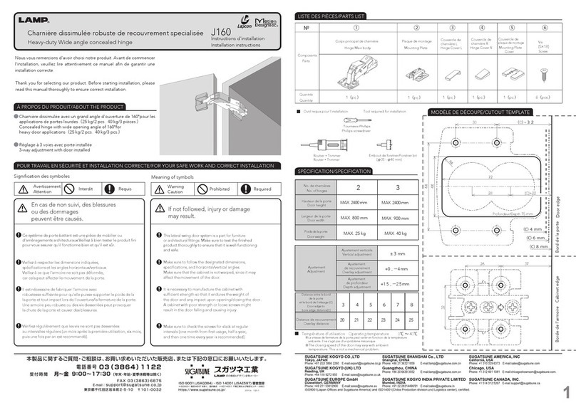
Lapcon Door Damper
■
just before the complete closing and closes completely.
・The damper function reduces door slamming sounds and the door begins to close slowly
・This product is a SURFACE MOUNT TYPE door closer damper intended to be applied on the head frame.
・ This damper may not be able to slow down the door if it is closed with excessive force.
limited to replacement of the product.
・The warranty period is one year after the day of shipment. The company’s responsibility shall be
product, contact retailer.
・The company is conducting strict check on the products, however, if any defects are found on the
In case of failure, Sugatsune's liability is limited to the replacement of the products by a similar one.
・Sugatsune's waranty is for the product itself and does not extend to the installation as a whole.
reference.
Read this manual thoroughly for proper and safe installation. Please retain this manual for future
・This damper effectiveness maybe lessened when use in an environment subject to strong drafts.
・
This product is for indoor use only. Do not use in locations where it is in direct contact with water.
・ ℃Standard temperature of use is 0 to 40 .
Installation and usage notices
・The LDD may not pull the door completely closed when using and overly hard latch.
Body
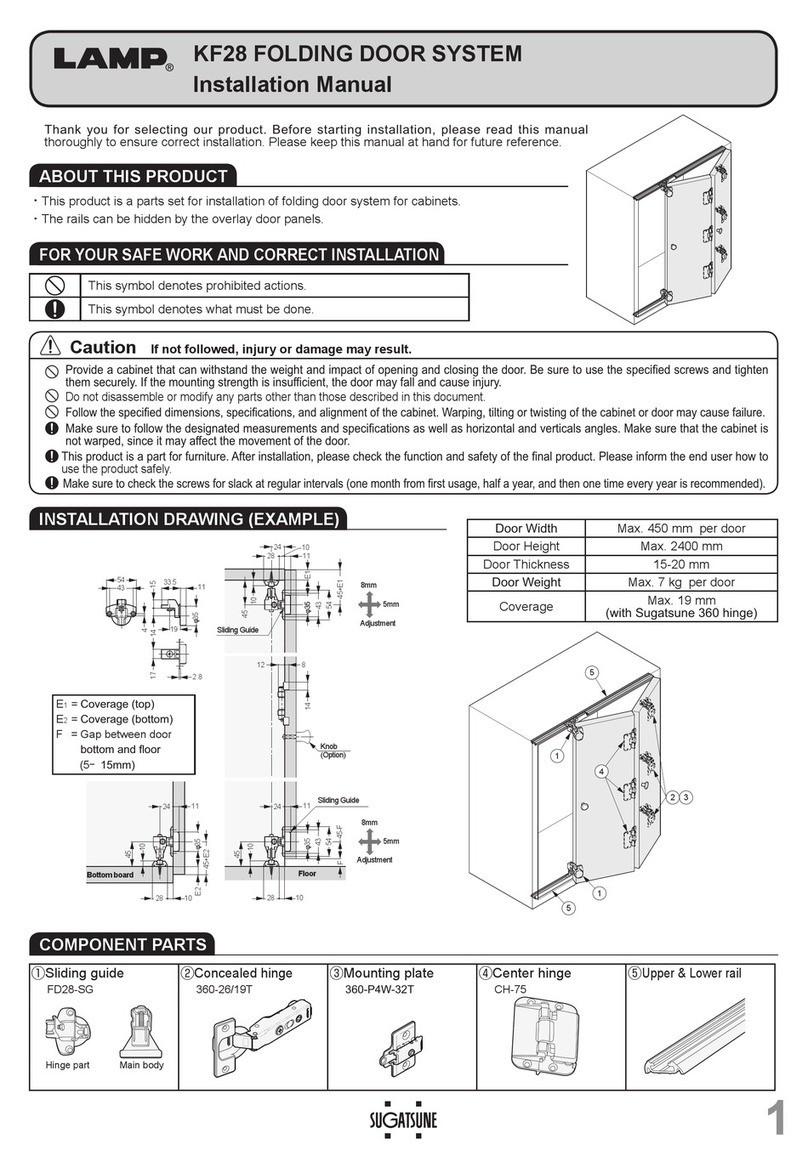
Left-hand opening type (LDD-S-L) is symmetrically opposed.
Product functions and features
This drawing shows a right-hand opening type (LDD-S-R).
Strike
interaction between the hinge and the LDD damper.
・Despite extensive in-house testing , we recommend that you test your installation for proper
・The strike plate is featured with vertical/horizontal adjustment functions.
Parts list
LDD-S PAT.P
・Featured with the function of door-closing power adjustment.
*LDD-S body : 1pcs■*Body cover : 1pcs■*Strike plate unit : 1 pcs■*Strike plate cover : 1 pcs■
・Quick and easy to install. Just mount it close to the vertical frame and door stop. (*Depends on the frame width.)
(nominal 3.5×30)
Body installation screw : 2pcs■(nominal 4×16)
Strike plate installation screw : 2pcs
*RIGHT HAND TYPE (LDD-S-R) SHOWN. LEFT HAND TYPE (LDD-S-L) SYMETRICALLY OPPOSITE.
■Instruction Manual (this manual) :1
Checking before the installation
Closing power adjustment screw
TM
●Installation
the Closing power adjustment screw.
・Attach the covers for the main unit and the
!
!
strike plate while keeping the door open.
This only changes the final closing power, not the
Indicator
High
Low
Higher Lower
damping force of the LDD-S.
4.Attaching the covers
・Closing power adjustment
Concealed hinge
Installation
・If C is between 20 mm and 25 mm:
Install and fully adjust the door, hinges and frame before installing the LDD-S
2.Strike plate installation procedure
・
Butt hinge ( Dimension D must be 60mm or less )・
Suggested hinge■
・Maximum door width: 900 mm (36")
・Door weight range: 15-40 kg (33.6-88 lbs.)
Applicable door specifications
③
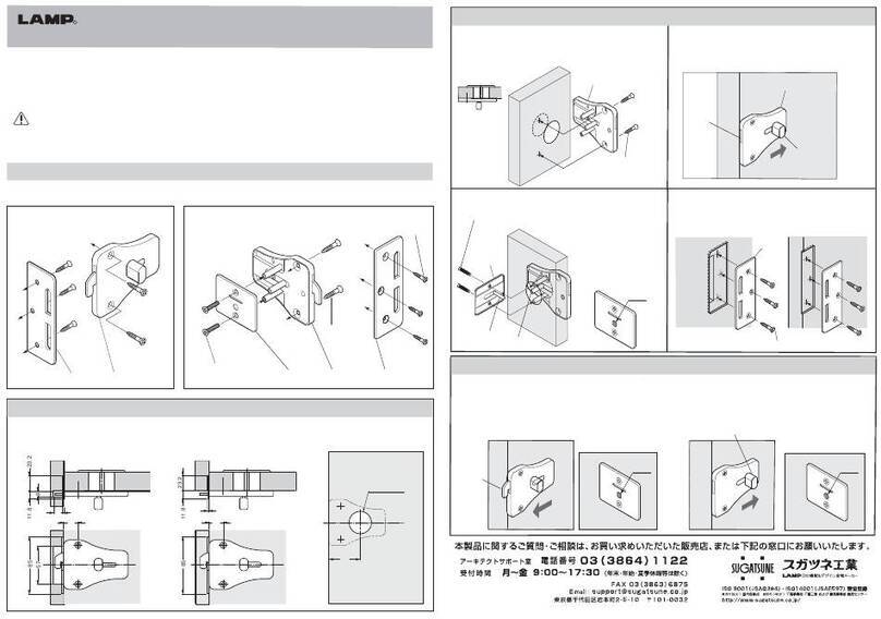
screw hole shown on the template.
Adjust the template so that it is parallele with the top of the door and mark the
in the square hole shown on the template.
Square hole
3.Adjustments
R
Unit:mm
Left-hand opening Right-hand opening
Mounting position and installation screw holes depend on the top frame mounting width C
FIG 1-A ・If C is 25 mm or more: FIG 1-B
OR
FIG 2 FIG 3 FIG 4
1.Main unit installation procedure
screws provided.
: Fix the strike plate with the installation
before opening and closing the door.
Proceed with the final adjustment
FIG 4
Screw holes
the strike plate. (See below.)
FIG 5
If necessary, carry out vertical and/or horizontal adjustments to
the guide groove on the strike plate as shown.
: Close the door carefully and make sure that the roller enters into
FIG 5
Loosen adjustment screw, adjust strike plate position and re-tighten
in order to check proper function of the LDD-S.
When adjustment is completed, open and close the door several times
Check roller position and adjust further if necessary.
screw.
Vertical adjustment screw
■Check you door opening side
・If the hinges are on your right when pulling the door open, choose the "Right-hand" opening type.
・If the hinges are on your left when pulling the door open, choose the "Left-hand" opening type.
■Size of door stopper and top frame (applicable size range)
A - Maximum height of door stopper: 15 mm
B - Distance from door to the back of the door stopper
(= door stopper + packing thickness): 23-33 mm
C - Minimum top frame mounting width: 20 mm
■
FIG 2-3: ①Deploy the arm and close the door slowly until the arm touches the door.
②Insert the template between the arm and the door so that the arm roller fits
Horizontal adjustment screw
Closing power of the door can be adjusted by turning
132
32.3
50
152
Topframe
Doorstop
Door
B
A
C
Door
(This drawing shows a right-hand opening type (LDD-S-R). Left-hand opening type (LDD-S-L) is symmetrically opposed.)
Installationdrawing
Center of butt hinge
Hinge side mounting frame
Body
Strike
17.5
60
198
9
35
212
: Line up the LDD-S body with the top door stop and hinge
Hinge side mounting frame
Door stop
installation screws.
FIG 1-A
Door stop
side mounting frame. Fix the body with the provided body
Screw holes
FIG 1-B: Line up the LDD-S body with the top door stop and 25mm
away from the hinge side mounting frame. Fix the body with
the provided body installation screws.
C
Screw holes
Hinge side mounting frame
mm25
C
Arm


