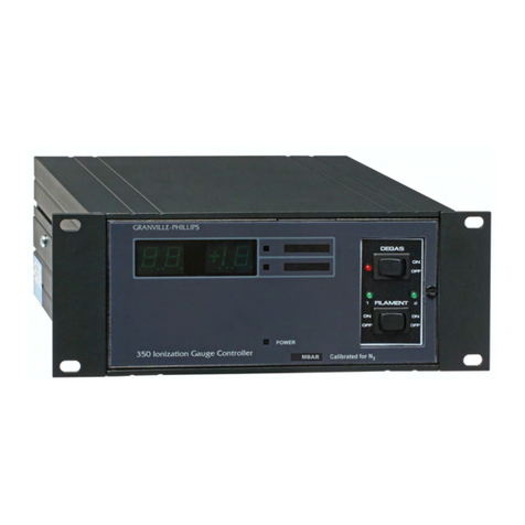
MKS 332 Series User manual

Series 332 Ionization Gauge Controller
Instruction manual part number 332004
Revision C - March 2020
Series 332
Instruction Manual


This Instruction Manual is for use with all
Series 332 Ionization Gauge Controllers.
Series 332 Ionization Gauge Controller
Series 332
Instruction Manual
© 2020 MKS Instruments, Inc. All rights reserved. Granville-Phillips®is a registered
trademark, and mksinstTM is a trademark of MKS Instruments, Inc. All other
trademarks and registered trademarks are the properties of their respective owners.
Customer Service / Technical Support:
MKS Global Headquarters
2 Tech Drive, Suite 201
Andover MA, 01810 USA
Phone: +1-833-986-1686
Visit our website at www.mksinst.com

4 Instruction Manual 332004
Table of Contents
Introduction & Safety Notices
Receiving Inspection............................................................................................................... 6
International Shipment........................................................................................................... 6
Limited Warranty..................................................................................................................... 6
Explosive Gases ...................................................................................................................... 7
Implosion / Explosion ............................................................................................................. 7
Safety/Warning Notices ......................................................................................................... 8
Grounding................................................................................................................................ 8
1.1 General Description ........................................................................................................ 9
Available Options ............................................................................................................. 9
Convectron Gauge Option ..................................................................................... 9
1.2 Installation....................................................................................................................... 9
Mounting Configurations................................................................................................. 9
Ionization Gauge Types and Installation ......................................................................10
Ion Gauge Cable Connections ......................................................................................11
System Ground Test Procedure....................................................................................12
1.3 Operation .......................................................................................................................14
Ion Gauge Theory of Operation.....................................................................................14
Emission Current Adjustment .......................................................................................15
Table 1-1...............................................................................................................15
Example 1.............................................................................................................15
Example 2.............................................................................................................15
Example 3.............................................................................................................15
Analog Output.......................................................................................................16
Overpressure Shutdown ......................................................................................19
Degas....................................................................................................................19
1.4 Calibration ......................................................................................................................19
Electrometer Zero..........................................................................................................19
Electrometer Log Amplifier............................................................................................19
Summary ........................................................................................................................20
1.5 Specifications ................................................................................................................20
2.1 General Description ......................................................................................................23
2.2 Safety Instructions ........................................................................................................23
Explosive Gases ...................................................................................................23
Limitation of Use of Compression Mounts .........................................................23
Convectron Gauge Mounting Position ................................................................23
Overpressure Conditions .....................................................................................23
High Indicated Pressure ......................................................................................24
Chemicals .............................................................................................................24
Sensor Failure ......................................................................................................24
Tube Contamination ............................................................................................24
2-3 Convectron Gauge Theory of Operation ......................................................................24
2.4 Convectron Gauge Installation......................................................................................25
Important Precautions for Gauge Installation....................................................25
Convectron Gauge Orientation............................................................................26

Instruction Manual 332004 5
Compression Mount (Quick Connect).................................................................27
1/8 NPT Mount ....................................................................................................27
NW10, 16, 25 and 40KF Flange Mount.............................................................27
Gauge Cable Connections ...................................................................................27
2.5 Operation .......................................................................................................................28
Special Considerations for Use Below 10-3 Torr..........................................................28
Use with Gases other than N2and Air ................................................................28
Indicated vs. True Pressure Curves ....................................................................28
Analog Output (Logarithmic) .........................................................................................33
Analog Output (Non linear)..................................................................................33
2.6 Calibration .....................................................................................................................34
Zero Adjustment...................................................................................................34
Atmosphere Adjustment ......................................................................................35
Full Scale Adjustment (Internal)..........................................................................35
Zero Adjustment (Internal) ..................................................................................35
3.1 General Description .......................................................................................................36
3.2 Troubleshooting ............................................................................................................37
General Symptoms/Possible Causes...........................................................................37
Convectron Gauge Bakeout Procedure........................................................................38
Cleaning a Convectron Gauge ......................................................................................38
Technical Support and Service.....................................................................................39

6 Instruction Manual 332004
Introduction & Safety Notices
Receiving Inspection
On receipt of your equipment, inspect all material for damage. Confirm that the shipment
includes all items ordered. If items are missing or damaged, submit a claim as stated below
for a domestic or international shipment, whichever is applicable.
If materials are missing or damaged, the carrier that made the delivery must be notified
within 15 days of delivery, or in accordance with Interstate Commerce regulations for the
filing of a claim. Any damaged material, including all containers and packaging, should be
held for carrier inspection. If the shipment is not correct for reasons other than shipping
damage, contact the MKS Customer Service Department, Phone: +1-833-986-1686, or
email: insidesales@mksinst.com.
International Shipment
Inspect all materials received for shipping damage and confirm that the shipment includes
all items ordered. If items are missing or damaged, the airfreight forwarder or airline making
delivery to the customs broker must be notified within 15 days of delivery. The following
illustrates to whom the claim is to be directed.
If an airfreight forwarder handles the shipment and their agent delivers the
shipment to customs, the claim must be filed with the airfreight forwarder.
If an airfreight forwarder delivers the shipment to a specific airline and the airline
delivers the shipment to customs, the claim must be filed with the airline.
Any damaged material, including all containers and packaging, should be held for carrier
inspection. If your shipment is not correct for reasons other than shipping damage, contact
MKS.
Limited Warranty
This product is warranted against defects in materials and workmanship for 1 year from the
date of shipment provided the installation, operating and preventive maintenance
procedures specified in this instruction manual have been followed. MKS will, at its option,
repair, replace, or refund the selling price of the product if it proves to be defective in
materials or workmanship during the warranty period, provided the item is returned to MKS
together with a written statement of the problem.
Defects resulting from or repairs necessitated by misuse or alteration of the product or any
cause other than defective materials or workmanship are not covered by this warranty.
MKS INSTRUMENTS, INC. EXPRESSLY DISCLAIMS ANY OTHER WARRANTY, WHETHER
EXPRESSED OR IMPLIED, INCLUDING BUT NOT LIMITED TO THE IMPLIED WARRANTIES OF
MERCHANTABILITY AND FITNESS FOR A PARTICULAR PURPOSE. UNDER NO
CIRCUMSTANCES SHALL MKS INSTRUMENTS, INC. BE LIABLE FOR CONSEQUENTIAL OR
OTHER DAMAGES RESULTING FROM A BREACH OF THIS LIMITED WARRANTY OR
OTHERWISE.

Instruction Manual 332004 7
WARNING
Read this instruction manual before installing, using, or servicing this
equipment. If you have any doubts about how to use this equipment safely,
contact MKS.
DANGER, HIGH VOLTAGE
180 VDC is present in the 332 Controller, the gauge cable, and the ion gauge
when the gauge is turned ON.
Explosive Gases
Do not use Series 332 instruments to measure the pressure of explosive or combustible
gases or gas mixtures. Ionization gauge filaments operate at high temperatures.
Implosion / Explosion
Glass ionization gauges, if roughly handled, may implode under vacuum causing flying glass
which may injure personnel. If pressurized above atmospheric pressure, glass tubes may
explode. A substantial shield should be placed around vacuum glassware to prevent injury to
personnel.
Danger of injury to personnel and damage to equipment exists on all vacuum systems that
incorporate gas sources or involve processes capable of pressuring the system above the
limits it can safely withstand.
For example, danger of explosion in a vacuum system exists during backfilling from
pressurized gas cylinders because many vacuum devices such as ionization gauge tubes,
glass windows, glass belljars, etc., are not designed to be pressurized.
Install suitable devices that will limit the pressure from external gas sources to the level that
the vacuum system can safely withstand. In addition, install suitable pressure relief valves or
rupture disks that will release pressure at a level considerably below that pressure which the
system can safely withstand.
Suppliers of pressure relief valves and pressure relief disks are listed in Thomas Register
under "Valves, Relief", and "Discs, Rupture".
Confirm that these safety devices are properly installed before installing the 332 Ionization
Gauge Controller (IGC). In addition, check that (1) the proper gas cylinders are installed, (2)
gas cylinder valve positions are correct on manual systems, and (3) the automation is
correct on automated systems.

8 Instruction Manual 332004
Safety/Warning Notices
WARNING
Operation of the 332 Ionization Gauge Controller with line voltage other than
that selected by the power supply line voltage selector can cause damage to
the instrument and injury to personnel.
WARNING
It is the installer's responsibility to ensure that the automatic signals provided
by the process control module are always used in a safe manner.
Carefully check manual operation of the system and the setpoint
programming before switching to automatic operation. Where an equipment
malfunction could cause a hazardous situation, always provide for fail-safe
operation.
WARNING
Do not attach cables to glass gauge pins while the gauge is under vacuum.
Accidental bending of the pins may cause the glass to break and implode.
Cables, once installed, should be secured to the system to provide strain relief
for the gauge tube pins.
WARNING
Safe operation of vacuum equipment, including the 332 Ionization Gauge
Controller, requires grounding of all exposed conductors of the gauges and
the Controller and the vacuum system. LETHAL VOLTAGES may be
established under some operating conditions unless correct grounding is
provided.
Ion producing equipment, such as ionization gauges, mass spectrometers, sputtering
systems, etc., from many manufacturers may, under some conditions, provide sufficient
electrical conduction via a plasma to couple a high voltage electrode potential to the
vacuum chamber. If exposed conductive parts of the gauge, controller, and chamber are not
grounded, they may attain a potential near that of the high voltage electrode during this
coupling. Potential fatal electrical shock could then occur because of the high voltage
between these exposed conductors and ground.
During routine pressure measurement, using ionization gauge controllers from any
manufacturer, about 160V may become present on ungrounded conductors at pressures
near 10-3 Torr. All isolated or insulated conductive parts of the controller, the gauge, and the
vacuum system must be grounded to prevent these voltages from occurring.
Grounding
Grounding, though simple, is very important! Be certain that the ground circuits are correctly
used on all ion gauge power supplies, gauges, and vacuum chambers, regardless of their
manufacturer, for this phenomenon is not peculiar to MKS equipment. Refer to all Safety
Instructions and Section 1.2, Installation, for additional information. If you have questions,
or wish additional labels or literature, please contact one of our technical personnel.

Instruction Manual 332004 9
Chapter 1
Series 332 Vacuum Gauge Controller
1.1 General Description
The 332 Vacuum Gauge Controller (VGC) measures pressure from less than 1 x 10⁻⁹ Torr
(1.3 x 10⁻⁹ mbar or 1.3 x 10⁻⁷ Pa) to 1 x 10⁻³ Torr, air equivalent, using a standard Bayard-
Alpert ionization gauge. Pressure readout is via a logarithmic analog voltage on the I/O
connector.
The 332 VGC is a modular instrument intended for computer control only with no external
controls or adjustments. Line voltage is fixed at 105-125 VAC, 50-60 Hz unless otherwise
indicated on the front panel.
Available Options
Convectron Gauge Option
The 332 VGC can be ordered with a factory installed Convectron Gauge option which allows
pressure reading in the range of 1 x 10⁻⁴ Torr to 1000 Torr.
1.2 Installation
Mounting Configurations
The 338 VGC should be mounted in a location with free air flow and ambient temperature
less than 40 oC. When mounting, allow a 1" minimum air gap between units for cooling.
The 332 VGC can be mounted to a surface using the four 10-32 threaded inserts located on
the end opposite the cables. See Figure 1-1. It may also be secured using "L" brackets
attached under the screws to the cover. Up to three modules may be mounted on a 3-1/2"
high by 19" long standard rack panel.

10 Instruction Manual 332004
Figure 1-1 332 VGC Dimensions
Ionization Gauge Types and Installation
WARNING
Do not attach cables to glass gauge pins while the gauge is under vacuum.
Accidental bending of the pins may cause the glass to break and implode.
Cables, once installed, should be secured to the system to provide strain relief
for the gauge tube pin.
The 332 VGC operates a Bayard-Alpert type or equivalent ionization gauge. Coated Iridium
filament type gauges are recommended since at higher pressures they provide longer
operating life and greater burnout resistance. When installing an ion gauge, note that if placed
near the pump, the pressure in the gauge may be considerably lower than in the rest of the
system. If placed near a gas inlet or source of contamination, the pressure in the gauge may
be higher.
If an unshielded gauge is placed near an electron beam evaporation source or used in a
sputtering system, spurious electrons or ions may disturb the measurement. Screens or other
shielding should be placed between the gauge and the system if spurious charged particles or
severe electromagnetic interference is present. Consideration should also be given to
electrostatic shielding of glass tubulated gauges when measuring pressures near their x-ray
limits.
MKS offers 2 cable types for use with the 332 VGC. One has a standard connector for the
Series 274 tubulated gauge tubes. One has individual pin sockets for use with non-standard
pin configurations as well as with MKS "nude" tubes. To use the second filament of a dual
filament gauge, the cable connector at the gauge is removed and rotated 180o, then
reinstalled.

Instruction Manual 332004 11
Figure 1-2 shows typical tube base configurations used with the standard connector cables.
Figure 1-2 Standard B-A Gauge Configurations
Ion Gauge Cable Connections
The 9-pin “D” I/O connector is used to operate the Bayard-Alpert ionization gauge and
output the analog voltage corresponding to pressure. See Table 1-1.

12 Instruction Manual 332004
Pin
Function
1
Ion Gauge ON/OFF. A momentary ground (100 milliseconds minimum) will
cause the filament circuit to change state. This can be either from an
unpowered switch (or relay closure) or from a powered circuit which uses a
pull up voltage of less than 50 Vdc.
2
Ground
3
Analog output
4
+12 Vdc (for test purposes only)
5
Degas Status. Open collector transistor (grounded emitter) rated at 40 V
max VCE, 100 mA max. Transistor OFF = gauge OFF.
Transistor ON = gauge ON.
6
Degas ON/OFF. Same operation as pin 1.
7
Ground
8
Emission current sense. Voltage proportional to emission current a Vdc = 1
mAdc, 110 ohms impedance. (Note: Grounding this pin will increase the
emission current a factor of 10).
9
Ion Gauge Status. Same as degas status.
System Ground Test Procedure
Procedure: Physically examine the grounding of both the 338 VGC and the vacuum chamber.
Is there an intentional heavy duty ground connection to all exposed conductors on the vacuum
chamber? There should be. Note that a horizontal "O" ring or "L" ring gasket, without metal
clamps, can leave the chamber above it electrically isolated. Power can be delivered to
mechanical and diffusion pumps without any ground connections to the system frame or
chamber. Water line grounds can be lost by a plastic or rubber tube interconnection. What was
once a carefully grounded vacuum system can, by innocent failure to reconnect all ground
connections, become a very dangerous device. Use the following procedure to test each of
your vacuum systems which incorporate an ionization gauge.
This procedure uses a conventional volt-ohm meter (VOM) and resistor (10 ohm, 10 watt).
1. With the gauge controller turned off, test for both dc and ac voltages between the
metal parts of the vacuum chamber and the power supply chassis.
2. If no voltages exist, measure resistance. The resistance should not exceed 2 ohms. Two
ohms, or less, implies commonality of these grounds that should prevent the plasma
from creating a dangerous voltage between them. This test does not prove that either
connection is earth ground, only that they are the same. If more than 2 ohms is
indicated, check with your electrician.

Instruction Manual 332004 13
3. If ac or dc voltages exist and are less than 10 volts, shunt the meter with a 10 ohm, 10
watt resistor. Repeat the voltage measurement. With the shunt in place across the
meter, if the voltage remains at 83% or more of the unshunted value, commonality of
the grounds is implied. Repeat the measurements several times to be sure that the
voltage ratio is not changing with time. If,
this should prevent the plasma from creating a dangerous voltage between these
grounds. If more than 10 volts exists between grounds, check with your electrician.
Figure 1-3 Correct System Grounding
4. If the voltage change in Step 3 is greater than 17%, due to the placement of the shunt,
it complicates the measurement. The commonality of the grounds may be satisfactory
and the coupling poor, or the commonality could be poor! Your electrician should be
asked to check the electrical continuity between these two ground systems. The
placement of a second ground wire, (dashed line in Figure 1.5), between the vacuum
chamber and the VGC chassis is not a safe answer for large currents could flow through
it. Professional help is recommended.
more,.83=
shunted)Voltage(un unted)Voltage(sh

14 Instruction Manual 332004
1.3 Operation
Ion Gauge Theory of Operation
The functional parts of a typical ionization gauge are the filament (cathode), grid (anode) and
ion collector, which are shown schematically in Figure 1-9. These electrodes are maintained by
the gauge controller at +30, +180, and 0 volts, relative to ground, respectively.
Figure 1-4 Ion Gauge Schematic
The filament is heated to such a temperature that electrons are emitted and accelerated
toward the grid by the potential difference between the grid and filament. Most of the
electrons eventually collide with the grid, but many first traverse the region inside the grid one
or more times.
When an energetic electron collides with a gas molecule an electron may be dislodged from
the molecule leaving it with a positive charge. Most ions are then accelerated to the collector.
The rate at which electron collisions with molecules occur is proportional to the density of gas
molecules, and hence the ion current is proportional to the gas density (or pressure, at
constant temperature).
The amount of ion current for a given emission current and pressure depends on the ion gauge
design. This gives rise to the definition of ion gauge "sensitivity", frequently denoted by "K".
Bayard-Alpert type gauges typically have sensitivities of 10/Torr when used with nitrogen or
atmosphere. Sensitivities for other gases are given in Section 2-3.
The ion gauge controller varies the heating current to the filament to maintain a constant
pressure)xcurrentmissioncurrent/(eion=K

Instruction Manual 332004 15
electron emission and measures the ion current to the collector. The pressure is then
calculated from these data.
Ion gauge degas is accomplished by resistance heating (I2R). During I2R degas a large current
is passed through the grid structure raising its temperature and driving off contaminants.
Some ion gauge tube designs do not allow I2R degas.
Emission Current Adjustment
The IGC has been factory calibrated at 1 mAdc emission current making it direct reading for
N2using a gauge tube with a sensitivity of 10/Torr. The IGC also gives the same indication
for air as for N2within the accuracy of the instrument. To make the IGC direct reading for
other gauge tubes or for gases other than N2and air, use Eq. (1) to determine the correct
emission current setting.
where r is given in Table 1-1.
Table 1-1
Gas
N2
He
Ne
Ar
Kr
Xe
H2
r
1
0.15
0.24
1.19
1.86
2.73
0.46
Ion gauge sensitivity ratios, r, derived from data obtained by
S. Dushman and A. H. Young, Phys, Rev. 68 278 (1945).
Example 1
If your tube has a sensitivity of 25/Torr for N2, then the emission current to make the
controller direct reading for N is
Example 2
If your tube has a sensitivity of 15/Torr for N2and you wish to measure argon pressure, the
emission setting to make the controller direct reading for argon is
Example 3
Assume you have a tube with a gauge sensitivity of 10/Torr for N2and wish to make the
controller direct reading for helium. Here Eq. 1 is not applicable for it calls for an emission
current beyond the capability of the controller.
Eq. 1 ie=.01
(r)(GaugeTubeSensitivityforN2)
ie= .01
1x25 = .4mA
ie=.01
1.19x15 = .56mA

16 Instruction Manual 332004
In such a situation one possibility is to set the emission current at 1/10 of the emission
called for by Eq. 1, i.e., .67 mA for the assumed case, and remember to increase the
indicated reading by a factor of 10. Under these assumptions a reading of 5 x 10⁻⁶ Torr for
helium corresponds to a pressure of helium of 5 x 10⁻⁵ Torr.
Once the emission current requirement has been established it may be adjusted as follows:
1. Remove the cover from the 332 VGC and locate the Iepotentiometer.
2. Monitor the DC voltage at pin 8 of the I/O connector with respect to ground using a
digital voltmeter.
3. The voltage at pin 8 is related to emission current by a factor of 1.0 Vdc being equal
to 1.0 mAdc. Adjust the Iepot for the desired voltage. The Ierange is from less than
0.1 mA to 1.2 mA.
4. For operation at low pressures, the emission current can be increased a factor of 10
by applying a ground (pin 2 or 7) to pin 8 of the connector. Since this will result in 10
times more collector current the analog output will increase 1.00 Vdc for a given
pressure. This must be corrected for in the program. Note that the voltage at pin 8
can no longer be monitored as an indicator of emission current.
Analog Output
This signal is proportional to the logarithm of the pressure with 0 volts at 1 x 10-11 Torr at 1
mA emission or 1 x 10-12 Torr at 10 mA emission. When the ion gauge is turned OFF, the
output will switch to slightly over +10 Vdc. See Figures 1-5 and 1-6.
ie=.01
0.15x10 = 6.67mA

Instruction Manual 332004 17
Figure 1-5 Analog Output in Vdc at 1.0 mA Emission

18 Instruction Manual 332004
Figure 1-6 Analog Output in Vdc at 10 mA Emission

Instruction Manual 332004 19
Overpressure Shutdown
The 332 VGC is preset by fixed component values to shut down the ion gauge should
pressure rise above 1 x 10⁻² Torr at 1 mA emission or 1 x 10⁻³ Torr at 10 mA emission.
Degas
Degassing of the ion gauge is accomplished by I2R heating of the grid utilizing a separate
winding of the transformer. Pressure reading during degas is allowable. To activate the
degas circuit, the IG ON circuit must be first activated. This assures there is a vacuum in the
system prior to degas. The degas circuit will turn OFF if the IG ON circuit is turned OFF.
When and how long to degas is a matter of user preference. In our experience, degas, when
working with pressures higher than the 10-6 Torr range, is of little or no value. As pressure
decreases from this point it becomes more necessary to read a true value of pressure.
Generally, degassing for 5 minutes or less is satisfactory although it can be left on
indefinitely without harm to the gauge tube or controller.
1.4 Calibration
Electrometer Zero
There is an internal zero adjust potentiometer which rarely, if ever, will require adjustment.
Since this is a log type of circuit, which does not zero in a conventional manner, we
recommend checking by disconnecting the collector cable input while the gauge is on and
monitoring the analog output voltage. If it is below +2 Vdc, this indicates that the zero is
below 1 x 10⁻⁹ Torr. Readings in the 10-9 Torr range could be effected a maximum of 10% of
F. S., reading in the 10-8 Torr range 1% and so on. For further information refer to Step 3 of
the following procedure.
Electrometer Log Amplifier
To calibrate the electrometer circuit you need a DVM with at least 4 digits resolution and a
picoamp source such as the Keithley 220 programmable current source.
1. Electrometer offset adjustment
This adjustment creates an offset voltage which is the same for any input current.
With an input current of 1 x 10⁻⁸ A, the offset adjustment can be done without
effects from the zero or scale adjustments. Adjust the offset potentiometer, R33,
for 5.00 V output.
2. Electrometer scale adjustment
The scale or gain adjustment sets the slope of the curve. Set the current source
for 1 x 10⁻⁵ A and adjust the scale potentiometer, R33, for 8.00 V output.
3. Electrometer zero adjustment
The zero adjustment compensates for the current offset. It is difficult to get a true zero with
this circuit because as the electrometer reading gets lower, the response time increases.
The circuit also becomes more sensitive to changes in the zero adjustment as the output

20 Instruction Manual 332004
approaches zero. For an accurate reading at very low pressures, set the current source for 1
x 10-11 A. Adjust the zero potentiometer, R19, for 2.00 V output. For a 10/Torr gauge, this
will yield accurate results at 1 x 10⁻⁹ Torr with 1 mA emission. This adjustment can be made
without a current source. With no input current, adjust the zero potentiometer, R19, for an
output voltage at least 1 V lower than the lowest expected reading. This will yield less than
+10% error in the lowest decade and decrease by a factory of 10 for each successive higher
decade.
Summary
Input (A)
Adjustment
Output (Vdc)
1 x 10⁻⁸
Offset (R33)
5.00
1 x 10⁻⁵
Scale (R39)
8.00
1 x 10-11
Zero (R19)
2.00
1.5 Specifications
Physical
Width
5.1 inches
Height
3.5 inches
Depth
9.5 inches (allow 3 inches for cable connectors)
Weight
8.0 pounds
Electrical
Voltage
105 to 125 VAC
Frequency
50 to 60 Hz
Power
100 watts max.
Fuse Ratings
Line fuse: 1.25A (90-130V),.60A (200-260V)
Mounting
Four threaded 10-32 holes on the bottom of the Controller. Can
also use 4 (L) brackets same as furnished with a 307 power
supply.
Environmental Temperature
0oC to 40 oC
Pressure Range
Less than 1 x 10⁻⁸ Torr to 5 x 10⁻³ Torr with 1 mA emission and
gauge sensitivity of 10/Torr. (Less than 1 x 10⁻⁹ Torr to 5 x 10⁻⁴
Torr at 10 mA emission.)
Emission Range
Normally set for 1 mA. Adjustable from .1 to 1.2 mA to correct
for tubes with sensitivities between 8 and 100/Torr. External
ground will switch set current one decade higher.
Pressure Analog Output
Logarithmic: 1 Vdc/decade.
0 volts = 1 x 10-11 Torr (theoretical) at 1 mA.
Filament & Degas Control
Momentary ground to input/output connector pins will cause the
circuit to change state.
Degas
I2R approximately 7 VAC, 8 A (56 watts). Pressure reading
available during degas. Degas inoperative unless the gauge is
Table of contents
Other MKS Controllers manuals