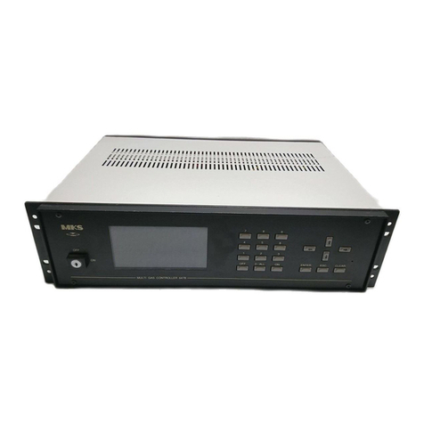
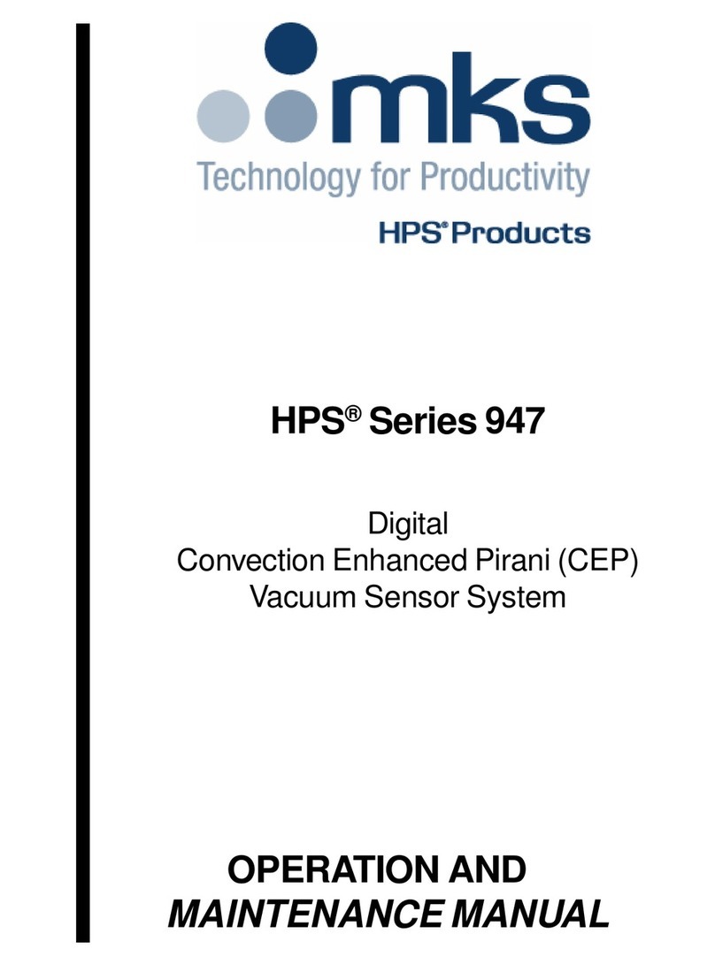
MKS 959 Series User manual

959 Hot Cathode Controller
OPERATION AND
MAINTENANCE MANUAL

959 Hot Cathode Controller
November 2000
PART #100011229 Rev. A

Part # 000000000XX
_ _
Serial #_ _ _ _ _ _ _ _ _
Please fill in these numbers and have
them readily available when calling for service
or additional information.
(The part number can be found on
your packing slip, and both the part number
and serial number are located on the bottom
side of the housing.)
For more information or literature, contact:
MKS Instruments, Inc., HPS®Products
5330 Sterling Drive
Boulder, CO 80301 USA
Phone: 303-449-9861
800-345-1967
FAX: 303-442-6880
1999 MKS Instruments, Inc., HPS® Products. All rights reserved.

Table of Contents
Table of Contents
1.Package Contents ................................................................. 1
2. Safety Information.................................................................. 2
2.1 Symbols Used in this Manual ........................................................... 2
2.2 Safety Precautions ........................................................................... 3
3.Specifications ........................................................................ 5
3.1 Controller .......................................................................................... 5
3.2 Standard Pirani................................................................................. 6
3.3 Convection Enhanced Pirani ............................................................ 7
3.4 Low Power Nude Tube...................................................................... 8
3.5 Mini BA ............................................................................................. 9
4.1 Front View....................................................................................... 10
4.2 Rear View ....................................................................................... 10
4.Feature and Control Locations............................................. 11
4.3 Side View ........................................................................................ 13
4.4.1 Standard Pirani ..................................................................... 13
4.4.2 Convection Enhanced Pirani................................................. 14
4.4.3 Low Power Nude Tube .......................................................... 14
4.4.4 Mini BA.................................................................................. 15
5.Typical Applications for the 959 Hot Cathode Controller ...... 16
6. About the 959 Hot Cathode Controller................................. 17
7. Installing the 959 Hot Cathode Controller ............................ 19
7.1 Controller Installation...................................................................... 19
7.1.1 Controller Mounting .............................................................. 19
7.2 Pirani Sensor Installation ......................................................... 19
7.2.1 General Pirani Information ............................................. 19
7.2.2 Locating a Pirani Sensor ................................................ 20
7.2.3 Preventing Contamination in a Pirani Sensor................. 20
7.2.4 Cleaning the Pirani Sensor............................................. 20
7.2.5 Connecting a Pirani Sensor to a Vacuum Chamber....... 20
7.3 Series 315 / 345 Standard Pirani Sensor Installation ............. 21
7.3.1 Orienting the Series 315/345 Sensor ............................. 21
7.3.2 Connecting the Series 315/345 Sensor ......................... 21

7.3.2.1 Connecting the Series 315 Sensor to the 959
Controller. .......................................................................... 21
7.3.2.2 Connecting the Series 345 Sensor to the 959
Controller. .......................................................................... 22
7.3.3 Testing the Series 315/345 Sensor ................................ 23
7.4 Series 317 Convection Enhanced Pirani Sensor Installation .. 23
7.4.1 Orienting the Series 317 Sensor .................................... 23
7.4.2 Connecting the Series 317 Sensor ................................ 23
7.4.2.1 Connecting the Series 317 Sensor to the 959
Controller........................................................................... 23
7.4.3 Testing the Series 317 Sensor........................................ 24
7.5 Low Power Nude Tube and Mini BA Hot Cathode Sensor
Installation ...................................................................................... 25
7.5.1 Locating a Hot Cathode Sensor ..................................... 25
7.5.2 Preventing Contamination in a Hot Cathode Sensor...... 25
7.5.3 Cleaning the Hot Cathode Sensor.................................. 25
7.5.4 Orienting a Hot Cathode Sensor .................................... 25
7.5.5 Connecting a Hot Cathode Sensor................................. 25
7.5.5.1 Connecting a Hot Cathode Sensor to a Vacuum
Chamber............................................................................ 25
7.5.5.2 Connecting a Hot Cathode Sensor to the 959
Controller........................................................................... 26
7.5.6 Testing the Hot Cathode Sensor..................................... 27
7.6 Sensor Cable Diagrams and Pin Outs ..................................... 28
7.6.1 Series 315 ...................................................................... 28
7.6.2 Series 345 and Series 317 ............................................. 29
7.6.3 Low Power Nude Tube .................................................... 30
7.6.4 Mini BA ........................................................................... 30
7.6.5 Hot Cathode Connector Pin Out..................................... 31
7.7 Accessory Connector............................................................... 32
7.8 AC Power ................................................................................. 32
8. Operating the 959 Hot Cathode Controller .......................... 34
8.1 How the 959 Hot Cathode Controller Works .................................. 34
8.2 Controller Module Operation .......................................................... 34
8.3 Hot Cathode Sensor Module Operation ......................................... 35
8.4 Pirani Sensor Module Operation .................................................... 36
8.5 User Interface ................................................................................. 36
8.5.1 Controller Power Up.............................................................. 36
8.6 Controller Modes of Operation ....................................................... 36
8.6.1 Pressure Measurement Mode .............................................. 36
8.6.2 Set Point Mode...................................................................... 37
8.6.3 Set Up Mode ......................................................................... 37
8.6.4 Parameter Input Constraints ................................................. 37

8.6.5 Leak Test Mode..................................................................... 37
8.7 Front Panel Overview ..................................................................... 38
8.7.1 Front Panel Switch Definitions .............................................. 38
8.8 Pressure Measurement Modes ...................................................... 39
8.8.1 Normal Pressure Measurement............................................ 39
8.8.2 Control Pressure Measurement............................................ 39
8.8.3 Combined Pressure Measurement ....................................... 40
8.9 Set Point Operation ........................................................................ 40
8.9.1 Relay Set Point Operation..................................................... 40
8.9.2 Sensor Module Exceptions and Set Point Operation............ 41
8.9.3 Set Point Configuration Displays........................................... 41
8.9.4 Set Point 1 Value Assignment ............................................... 41
8.9.5 Set Point 1 Enable ................................................................ 42
8.9.6 Set Point 2 Value Assignment ............................................... 43
8.9.7 Set Point 2 Enable ................................................................ 43
8.9.8 Control Set Point Operation .................................................. 44
8.9.9 Control Set Point Constraints................................................ 44
8.9.10 Control Set Point Assignment ............................................. 45
8.9.11 Control Set Point Enable..................................................... 45
8.9.12 Protect Set Point Operation ................................................ 46
8.9.13 Protect Set Point Constraints .............................................. 46
8.9.14 Protect Set Point Assignment ............................................. 46
8.10 Set Up Configuration .................................................................... 47
8.10.1 Filament Select ................................................................... 47
8.10.2 Combined Pressure Measurement ..................................... 47
8.10.3 Combined Mode Constraints .............................................. 48
8.10.4 Hot Cathode Sensitivity....................................................... 48
8.11 Calibration .................................................................................... 49
8.11.1 Pirani ................................................................................... 49
8.11.2 Vacuum Calibration ............................................................. 49
8.11.3 Atmospheric Calibration...................................................... 49
8.11.4 Pirani Atmospheric Calibration ........................................... 50
8.11.5 Pirani Vacuum Calibration................................................... 50
8.11.7 Emission Current Assignment ............................................ 51
8.11.6 Degas Time......................................................................... 51
8.12 Leak Test Operation ..................................................................... 52
8.12.1 Entering Leak Test Mode .................................................... 52
8.12.2 Resetting the Baseline Pressure ........................................ 52
8.12.3 Audible Operation ............................................................... 52
8.12.4 Exiting Leak Test Mode ....................................................... 53
8.12.5 Leak Test Constraints.......................................................... 53
8.12.6 Using the Series 959 as a Leak Detector. .......................... 53
8.13 Leak Test Displays........................................................................ 56
8.13.1 Leak Sensor Assignment .................................................... 56
8.13.2 Pirani Sensor Leak Test Operation ..................................... 56
8.13.3 Hot Cathode Sensor Leak Test Operation .......................... 57
8.14 Status Readouts........................................................................... 58
8.14.1 Under Pressure................................................................... 58
8.14.2 Over Pressure..................................................................... 58
8.14.3 Low Emission ...................................................................... 59
8.15 Miscellaneous Displays ................................................................ 60
8.15.1 LCD Display Test................................................................. 60
8.15.2 Factory Reset...................................................................... 61
8.15.4 Front Panel Lock ................................................................. 61
8.16 Buffered Analog Output ................................................................ 62
8.17 Standard Pirani Pressure to Voltage Curve .......................... 63
8.18 Standard Pirani Pressure to Voltage Table ............................ 63
8.19 Convection Enhanced Pirani Pressure to Voltage Curve....... 64
8.20 Convection Enhanced Pirani Pressure to Voltage Table........ 64
8.21 Hot Cathode Curves .............................................................. 65
9. Maintaining The 959 Hot Cathode Controller....................... 66
9.1 Cleaning the Controller Front Panel ............................................... 66
9.3 Servicing the Controller.................................................................. 66
9.3 Replacing the Power Fuse ............................................................. 67
10. Using the 959 Hot Cathode Controller with Other Gases . 68
9.1 Adjusting System Sensitivity for Another Gas ................................ 68
10.1 Relative Sensitivity Table.............................................................. 69
11.Accessories ....................................................................... 70
12. ProductWarranty.............................................................. 72
13. Appendix A
Serial Communications............................................................ A1
13.1 Serial Communications Overview ................................................ A1
13.1.1 Message Format ................................................................. A1
13.1.2 Message Compatibility........................................................ A1
13.1.3 Serial Communications ....................................................... A1
13.2 Message Syntax ........................................................................... A2
13.2.1 Command Syntax ...............................................................A2
13.2.2 Query Syntax ......................................................................A2
13.2.3 Response Syntax................................................................A2
13.3 Addressed RS232 ........................................................................ A3
13.3.1 Message Syntax .................................................................A3
13.3.2 Field Definitions .................................................................. A3

13.3.2.1AttentionCharacter..................................................... A3
13.3.2.2Device Address .......................................................... A3
13.4 Message Handling........................................................................ A4
13.5 ASCII Command Set Definition ....................................................A4
13.6 Setup Messages........................................................................... A5
13.6.1 Set Point Value - SPx ..........................................................A5
13.6.2 Control Set Point Value - CSP.............................................A6
13.6.3 Protect Pressure - PRO ......................................................A7
13.6.4 Gauge Correction - GC.......................................................A8
13.6.5 Atmospheric Calibration -ATM ............................................A9
12.6.6 Vacuum Calibration - VAC ................................................. A10
13.6.7 Time to Degas -TD............................................................ A11
13.6.8 Front Panel Lock - FPL .....................................................A12
13.6.9 Factory Default - FD..........................................................A13
13.7 Control Messages ......................................................................A14
13.7.1 Active Filament - AF.......................................................... A14
13.7.2 Filament Power - FP ......................................................... A15
13.7.3 Degas Power - DG ............................................................ A16
13.7.4 Combined Pressure Measurement - CMB........................A17
13.7.5 Set Point Enable - ENx .....................................................A18
13.7.6 Emission Current - EC ......................................................A19
13.8 Status messages........................................................................A20
13.8.1 Pressure Reading - PRx ................................................... A20
13.8.2 Filament Status - FS ......................................................... A21
13.8.3 Degas Status - DS ............................................................ A22
13.8.4 Set Point Status - SSx....................................................... A23
13.8.5 Control Set Point Status - CSS .........................................A24
13.8.6 Units selection - U............................................................. A25
13.8.7 Manufacturer - MF ............................................................ A26
13.8.8 Model Designation - MD ................................................... A27
13.8.9 Device Type - DTx .............................................................A28
13.8.10 Serial Number - SNx .......................................................A29
13.8.11 Firmware Version - FVx ..................................................A30
13.8.12 Hardware Version - HVx..................................................A31
14. Appendix B
Serial Communication Error Codes .........................................B1
14.1 Error Codes .................................................................................. B1

1
959 Hot Cathode Controller
1.Package Contents
Before Unpacking your Series 959 Hot Cathode Controller, check all
surfaces of the packing material for shipping damage.
Please be sure that your Series 959 package contains these items:
1 - Series 959 Controller
1 - female, 15-pin subminiature D Accessory connector kit
1 - 10-foot power cord
1 - HPS®Products Series 959 Hot Cathode Controller User Manual.
A complete Series 959 System includes a Hot Cathode sensor and its
connecting cable, and optionally a Pirani sensor and cable, all of which are
sold separately. Please refer to page 70 for necessary ordering information.
If any items are missing from the package, call HPS®Products
Customer Service at 1-303-449-9861 or 1-800-345-1967.
Inspect the 959 System for visible evidence of damage. If it has been
damaged in shipping, notify the carrier immediately. Keep all shipping
materials and packaging for claim verification. Do not return the
product to HPS®Products.

2959 Hot Cathode Controller
2.1 Symbols Used in this Manual
The first two symbols below, that may be located on your Series 959,
identify critical safety concerns. They are used throughout this manual to
further define the safety concerns associated with the product.
The last two symbols identify other information in this manual that is
essential or useful in achieving optimal performance from the 959.
CAUTION: Refer to manual. Failure to read message
could result in personal injury or serious damage to the
equipmentorboth.
CAUTION: Risk of electrical shock.
Calls attention to important procedures, practices,
orconditions.
Failure to read message could result in damage
tothe equipment.
2.Safety Information

3
959 Hot Cathode Controller
2.2 Safety Precautions
The following general safety precautions must be observed during all
phases of operation of this instrument. Failure to comply with these
precautions or with specific warnings else where in this manual violates
safety standards of intended use of the instrument and may impair the
protection provided by the equipment. MKS Instruments, Inc. assumes no
liability for the customer’s failure to comply with these requirements.
Properly ground the controller:
This product is grounded through the grounding conductor of the power
cord. To avoid electrical shock, plug the power cord into a properly wired
receptacle before connecting it to the product input or output terminals. A
protective ground connection by way of the grounding conductor in the
power cord is essential for safe operation.
Upon loss of the protective-ground connection, all accessible conductive
parts (including knobs and controls that may appear to be insulating) can
render an electrical shock.
Do not substitute parts or modify instrument.
Do not install substitute parts or perform any unauthorized modification to
the instrument. Return the instrument to an MKS Calibration and Service
center for service and repair to ensure that all safety features are
maintained.
Use proper electrical fittings.
Dangerous voltages are contained within this instrument. All electrical
fittings and cables must be of the type specified, and in good condition. All
electrical fittings must be properly connected and grounded.
The Series 959 Controller contains lethal voltages when on.
High voltage is present in the cable and a Hot Cathode Sensor when the
Controller is turned on.
Use the proper power source.
This product is intended to operate from a power source that applies a
voltage between the supply conductors, or between either of the supply
conductors and ground, not more than that specified in the manual.
Use the proper fuse.
Use only a fuse of the correct type, voltage rating, and current rating, as
specified for your product.

4959 Hot Cathode Controller
Do not operate in explosive environments.
To avoid explosion, do not operate this product in an explosive environment
unless it has been specifically certified for such operation.
Service by qualified personnel only.
Operating personnel must not remove instrument covers. Component
replacement and internal adjustments must be made by qualified service
personnel only.
Use the proper power cord.
Use only a power cord that is in good condition and which meets the input
power requirements specified in the manual.
Use only a detachable cord set with conductors that have a cross-sectional
area equal to or greater than 0.75 mm2. The power cable should be
approved by a qualified agency such as VDE, Semko, or SEV.
Caution when handling an installed Hot Cathode sensor.
An installed Hot Cathode sensor, especially when installed within a
mounting nipple, may have areas exposed to the user that get hot
enough to burn skin.

5
959 Hot Cathode Controller
3. Specifications
3.1 Controller
Measuring Range * 1.0 x 10⁻¹⁰ to 1.0 x 10+3 Torr
1.3 x 10⁻¹⁰ to 1.3 x 10+3 mbar
1.3 x 10⁻⁸ to 1.3 x 10+5 Pa
Set Point Range * 5.0 x 10⁻¹⁰ to 9.5 x 10+2 Torr
6.5 x 10⁻¹⁰ to 1.2 x 10+3 mbar
6.5 x 10⁻⁸ to 1.2 x 10⁵Pa
Control Set Point Range * 1.0 x 10⁻⁴ to 1.0 x 10⁻² Torr
1.3 x 10⁻⁴ to 1.3 x10⁻² mbar
1.3 x 10⁻² to 1.3 x100Pa
Protect Set Point range 1.0 x 10⁻⁶ to 1.0 x 10⁻² Torr
1.3 x 10⁻⁶ to 1.3 x 10⁻² mbar
1.3 x 10⁻⁴ to 1.3 100Pa
Set Point hysteresis 10% of indicated pressure
Reproducibility Approximately +5%
Operating Temperature Range 50to 400C (410to 1040F)
Storage Temperature Range -100to 550C (140to 1310F)
Relative Humidity 80% max for T < 310C, decreasing
linearly to 50% max at 400C
Altitude 2000 m (6562 ft) max
Operating Environment Indoor use only
Insulation Coordination Installation (Overvoltage) Category II,
Pollution Degree 2
Power Requirement 100-240 VAC, 50-60 Hz
Mains Voltage Fluctuations not to exceed + 10%
Power Consumption (max) 70 Watts
Input Current (max) 1.0 Amp
*Range depends upon sensor options selected

6959 Hot Cathode Controller
Fuse Rating, Size T 1.6 A (5x22mm)
Number of Channels 2
Process Control Two nonvolatile, independently set,
pressure dependent set point relays
Relay contact Rating 2A @ 30 VAC or 30 VDC
resistive load, SPDT
Relayresponse < 1000 msec
Front Panel Controls Momentarypush buttons
Range for Sensor Sensitivity 0.1 to 99Torr-1
Electronic Casing Aluminum,anodized
Dimensions 33/4”x 10”x 33/4”
(WxDxH) (96 mm x 254 mm x 96 mm)
Size 1/4DIN
Weight 3.17 lb. (1.438 kg)
3.2 Standard Pirani
Pressure Range 1.0 x 10⁻⁴ to 1.0 x 10+2 Torr
1.3 x 10⁻⁴ to 1.3 x 10+2 mbar
1.3 x 10⁻² to 1.3 x 10+4 Pa
Set Point Range 2.0 x 10⁻⁴ to 9.5 x 10+1 Torr
2.6 x 10⁻⁴ to 1.2 x 10+2 mbar
2.6 x 10⁻² to 1.2 x 10+4 Pa
Control Set Point Range 1.0 x 10⁻⁴ to 1.0 x 10⁻² Torr
1.3 x 10⁻⁴ to 1.3 x 10⁻² mbar
1.3 x 10⁻² to 1.3 x 100Pa
Calibration Gas Air/nitrogen
Installation Orientation Any
Reproducibility 5% of indicated pressure @ Tconst
Materials Exposed to Vacuum SS 304, platinum, alloy alumina
ceramic, silver brazing alloy, nickel 200
Internal Volume 0.5 in.3(8.0 cm3) maximum

7
959 Hot Cathode Controller
OperatingTemperature Range 00to500C (320to 1220F)
Maximum BakeoutTemperature 500C(1220F)
Diameter 1.3 in. (34 mm)
Length 4.4 in. (112 mm)
Typical Weight (with KF Flange) 0.5 lb (0.2 kg)
Vacuum Connection NW 16 KF,
NW 25 KF
1/8”NPT-M,
with 1/2”compression seal option
8 VCR®-F (1/2”)
1 1/3”CF (non-rotatable)
2 3/4”CF (non-rotatable)
Ø15.0 mm x 30.0 mm tubulation
Ø18.0 mm x 30.0 mm tubulation
3.3 Convection Enhanced Pirani
Pressure Range 1.0 x 10⁻³ to 1.0 x 10+3 Torr
1.3 x 10⁻³ to 1.3 x 10+3 mbar
1.3 x 10⁻¹ to 1.3 x 10+5 Pa
Set Point Range 2.0 x 10⁻³ to 9.5 x 10+2 Torr
2.6 x 10⁻³ to 1.2 x 10+3 mbar
2.6 x 10⁻¹ to 1.2 x 10+5 Pa
Control Set Point Range 1.0 x 10⁻³ to 1.0 x 10⁻² Torr
1.3 x 10⁻³ to 1.3 x 10⁻² mbar
1.3 x 10⁻¹ to 1.3 x 100Pa
Calibration Gas Air/nitrogen
Installation Orientation Horizontal
Materials Exposed to Vacuum 304 Stainless steel, platinum,
glass, nickel
Repeatability 5% of indicated pressure @ Tconst
Internal Volume 2.0 in3 (33.0 cm3) maximum
Operating Temperature Range 00to 500C (320to 1220F)
Maximum Bakeout Temperature 1500C (3020F),
` 1000C (2120F) shielded;
without cable, connector/electronics
subassembly, and Controller

8959 Hot Cathode Controller
Diameter 1.6 in. (41 mm)
Length 4.4 in. (112 mm)
Typical Weight (with KF Flange) 0.5 lb (0.2 kg)
Vacuum Connection NW 16 KF
NW 25 KF
1/8”NPT-M, with 1/2”
compression seal option
4VCR®F(1/4”)
8VCR®F(1/2”)
1 1/3”CF (rotatable)
2 3/4”CF (rotatable)
Ø15.0 mm x 30.0 mm tubulation
Ø18.0 mm x 30.0 mm tubulation
3.4 Low Power Nude Tube
Pressure range 1.0 x 10⁻¹⁰ to 1.0 x 10⁻² Torr
1.3 x 10⁻¹⁰ to 1.3 x 10⁻² mbar
1.3 x 10⁻⁸ to 1.3 x 100Pa
Set Point Range 5.0 x 10⁻¹⁰ to 9.5 x 10⁻³ Torr
6.5 x 10⁻¹⁰ to 1.2 x 10⁻² mbar
6.5 x 10⁻⁸ to 1.2 x 100Pa
Protect Set Point Range 1.0 x 10⁻⁶ to 1.0 x 10⁻² Torr
1.3 x 10⁻⁶ to 1.3 x 10⁻² mbar
1.3 x 10⁻⁴ to 1.3 x 100Pa
Sensor Type Bayard-Alpert
Filament Type W orY 203
Sensitivity 9 Torr-1 (+20%)
Degas Power 20 W max
Operating voltages:
Grid 180 VDC
Filament bias 30 VDC
Filament 3 VDC @ 1.8 A
X-ray limit 3 x 10⁻¹⁰ Torr
Calibration Gas Air/nitrogen
Installation Orientation Any
Materials Exposed to Vacuum 304 SS, InconelâX-750, glass,
tungsten, platinum, nickel, either
yttria-coated iridium or tungsten

9
959 Hot Cathode Controller
Operating Temperature Range 00to 500C (320to 1220F)
Bakeout Temperature 600C (with cable attached)
3000 C max, with CF, cable removed
1500C max, with KF and Vitonâ
Seal, cable removed
Typical Weight (with CF Flange) 0.9 lb (0.4 kg)
Vacuum connection 2 3/4”CF (non-rotatable)
NW 40 KF
3.5 Mini BA
Pressure range 1.0 x 10⁻¹⁰ to 1.0 x 10⁻² Torr
1.3 x 10⁻¹⁰ to 1.3 x 10⁻² mbar
1.3 x 10⁻⁸ to 1.3 x 100Pa
Set Point Range 5.0 x 10⁻¹⁰ to 9.5 x 10⁻³ Torr
6.5 x 10⁻¹⁰ to 1.2 x 10⁻² mbar
6.5 x 10⁻⁸ to 1.2 x 100Pa
Protect Set Point Range 1.0 x 10⁻⁶ to 1.0 x 10⁻² Torr
1.3 x 10⁻⁶ to 1.3 x 10⁻² mbar
1.3 x 10⁻⁴ to 1.3 x 100Pa
Sensor Type Bayard-Alpert
Filament Type Y203
Sensitivity 12 Torr--1 (+20%)
Degas Power 5 W max
Operating voltages:
Grid 180 VDC
Filament bias 30 VDC
Filament 1.8 VDC @ 2A
X-ray limit 3 x 10⁻¹⁰ Torr
Calibration Gas Air/nitrogen
Installation Orientation Any
Materials Exposed to Vacuum 304 SS, glass, tungsten, platinum
clad molybdenum,
yttria-coated iridium
Operating Temperature Range 00to 500C (320to 1220F)

10 959 Hot Cathode Controller
BakeoutTemperature 600C (with cable attached)
3000 C max, with CF, cable removed
1500C max, with KF and Vitonâ
Seal, cable removed
Typical Weight (with CF Flange) .816 lb (.36 kg)
Vacuum connection 1”OD Tube
1 1/3”mini CF
2 3/4”CF
NW 25 KF
NW 40 KF
NW 16 KF
3/4”OD Tube
Design and / or specifications subject to change without Notice.

11
959 Hot Cathode Controller
4. Feature and Control Locations
4.1 Front View
1
234
5
6
7
8
4.2 Rear View
13
12
13
910 11
Table of contents
Other MKS Controllers manuals

MKS
MKS Compact Closed Loop Picomotor User manual

MKS
MKS P9B User manual

MKS
MKS nPC PCA0 User manual

MKS
MKS 332 Series User manual

MKS
MKS Granville-Phillips 358 series User manual

MKS
MKS 653B User manual

MKS
MKS 350 Series User manual

MKS
MKS 937B Series User manual

MKS
MKS Mass-Flo 1500 Series User manual

MKS
MKS HPS 947 Series User manual
Popular Controllers manuals by other brands

Sonnet
Sonnet Configuration tool and utilities installation manual

RocketRAID
RocketRAID 2680 installation guide

RADEMACHER
RADEMACHER 9470-4 manual

Resol
Resol DeltaSol ES manual

CentriPro
CentriPro AQUAVAR CPC Installation and operation manual

Regada
Regada MO 3 Installation, service and maintenance instructions