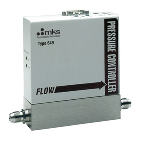
MKS MKS 153F User manual

-~
ARTISAN
®
~I
TECHNOLOGY
GROUP
Your definitive source
for
quality
pre-owned
equipment.
Artisan Technology
Group
Full-service,
independent
repair
center
with
experienced
engineers
and
technicians
on staff.
We
buy
your
excess,
underutilized,
and
idle
equipment
along
with
credit
for
buybacks
and
trade-ins
.
Custom
engineering
so
your
equipment
works
exactly as
you
specify.
•
Critical
and
expedited
services
•
Leasing
/
Rentals/
Demos
• In
stock/
Ready-to-ship
•
!TAR-certified
secure
asset
solutions
Expert
team
ITrust
guarantee
I
100%
satisfaction
All
tr
ademarks,
br
a
nd
names, a
nd
br
a
nd
s a
pp
earing here
in
are
th
e property of
th
e
ir
r
es
pecti
ve
ow
ner
s.
Visit our website - Click HERE

MKS Type 153F
Throttle Valve Controller
Instruction Manual
Six Shattuck Road
A
ndove
r
MA 01810-2449
Main: 978.975.2350
Fax: 978.975.0093
www.mksinst.com
123057-P1
Rev. A, 06/04
Instruction Manual

WARRANTY
Types 153F Throttle Valve Controller
MKS Instruments, Inc. (MKS) warrants that for two years from the date of shipment
the equipment described above (the “equipment”) manufactured by MKS shall be
free from defects in materials and workmanship and will correctly perform all date-
related operations, including without limitation accepting data entry, sequencing,
sorting, comparing, and reporting, regardless of the date the operation is performed
or the date involved in the operation, provided that, if the equipment exchanges
data or is otherwise used with equipment, software, or other products of others,
such products of others themselves correctly perform all date-related operations
and store and transmit dates and date-related data in a format compatible with
MKS equipment. THIS WARRANTY IS MKS’ SOLE WARRANTY CONCERNING
DATE-RELATED OPERATIONS.
For the period commencing with the date of shipment of this equipment and ending
two years later, MKS will, at its option, either repair or replace any part which is
defective in materials or workmanship or with respect to the date-related operations
warranty without charge to the purchaser. The foregoing shall constitute the
exclusive and sole remedy of the purchaser for any breach by MKS of this
warranty.
The purchaser, before returning any equipment covered by this warranty, which is
asserted to be defective by the purchaser, shall make specific written arrange-
ments with respect to the responsibility for shipping the equipment and handling
any other incidental charges with the MKS sales representative or distributor from
which the equipment was purchased or, in the case of a direct purchase from MKS,
with the MKS home office in Andover, Massachusetts, USA.
This warranty does not apply to any equipment which has not been installed and
used in accordance with the specifications recommended by MKS for the proper
and normal use of the equipment. MKS shall not be liable under any circumstances
for indirect, special, consequential, or incidental damages in connection with, or
arising out of, the sale, performance, or use of the equipment covered by this
warranty.
MKS recommends that all MKS pressure and flow products be calibrated
periodically (typically every 6 to 12 months) to ensure accurate readings. When a
product is returned to MKS for this periodic re-calibration it is considered normal
preventative maintenance not covered by any warranty.
THIS WARRANTY IS IN LIEU OF ALL OTHER RELEVANT WARRANTIES,
EXPRESSED OR IMPLIED, INCLUDING THE IMPLIED WARRANTY OF
MERCHANTABILITY AND THE IMPLIED WARRANTY OF FITNESS FOR A
PARTICULAR PURPOSE, AND ANY WARRANTY AGAINST INFRINGEMENT OF
A
NY PATENT.
06/04 123057-1 Rev. A

123057-P1
Rev A, 6/04
Throttle Valve Controller
J1
Input
J2 Power
Power
OPEN CLOSE
TYPE 153
CONTROL VALVE


Copyright © 2004 by MKS Instruments, Inc.
All rights reserved. No part of this work may be reproduced or transmitted in any form or by any
means, electronic or mechanical, including photocopying and recording, or by any information
storage or retrieval system, except as may be expressly permitted in writing by MKS Instruments,
Inc.
Printed in the United States of America
Cluster Gauge™ is trademark of MKS Instruments, Inc., Andover, MA
Parker®is a registered trademark of Parker Seals, Lexington, KY
Viton®is a registered trademark of DuPont Dow Elastomers, Inc., Wilmington, DE
Firmware version: 1.1x


Table of Contents
v
Table of Contents
Valve Safety Information.............................................................................................................1
Symbols Used in This Instruction Manual......................................................................1
Symbols Found on the Unit............................................................................................2
Safety Procedures and Precautions.................................................................................3
Sicherheitshinweise für das Ventil...............................................................................................5
In dieser Betriebsanleitung vorkommende Symbole......................................................5
Erklärung der am Gerät angebrachten Symbole.............................................................6
Sicherheitsvorschriften und Vorsichtsmaßnahmen.........................................................7
Informations relatives à la sécurité pour la valve.........................................................................9
Symboles utilisés dans ce manuel d'utilisation...............................................................9
Symboles apparaissant sur l'unité ...................................................................................10
Mesures de sécurité et précautions .................................................................................11
Medidas de seguridad de la válvula.............................................................................................13
Símbolos usados en este manual de instrucciones..........................................................13
Símbolos hallados en la unidad.......................................................................................14
Procedimientos y precauciones de seguridad..................................................................15
Chapter One: General Information .............................................................................................17
Introduction.....................................................................................................................17
How This Manual is Organized......................................................................................18
Customer Support...........................................................................................................18
Chapter Two: Installation ...........................................................................................................19
How To Unpack the Type 153 Unit................................................................................19
Unpacking Checklist..........................................................................................19
Interface Cables ..............................................................................................................20
Generic Shielded Cables....................................................................................21
Setup ...............................................................................................................................24
Dimensions ........................................................................................................24
Power Requirements..........................................................................................29

Table of Contents
vi
Grounding..........................................................................................................29
Mounting Instructions........................................................................................31
Connectors......................................................................................................................33
Power Connector (J2) ........................................................................................33
Input Connector (J1)..........................................................................................34
How To Connect to a PT-1 Portable RS-232 Terminal..................................................37
How To Connect to a Computer.....................................................................................38
How To Connect to a Type 146 Cluster Gauge™..........................................................39
Chapter Three: Overview............................................................................................................41
Control Mode..................................................................................................................41
Lead and Gain....................................................................................................41
External Connectors and Controls..................................................................................44
Power On LED...................................................................................................44
Input Connector (J1)..........................................................................................44
Power Connector (J2) ........................................................................................44
Hold/Normal Switch..........................................................................................45
Manual Valve Switch.........................................................................................45
Valve Open LED ...............................................................................................45
Valve Close LED...............................................................................................45
Internal Controls .............................................................................................................46
Dipswitch Bank..................................................................................................46
How To Change the Dipswitch Settings............................................................49
Power-Down Constants ..................................................................................................50
Power Up Conditions......................................................................................................50
Labels..............................................................................................................................51
Pump Label........................................................................................................51
Serial Number Label..........................................................................................51
Chapter Four: Operation .............................................................................................................53
General Information........................................................................................................53
Control Parameters..........................................................................................................53
RS-232 Communication Parameters...............................................................................54
How To Change the Communication Parameters..............................................55
RS-232 Protocol..............................................................................................................56

Table of Contents
vii
Message Format.................................................................................................56
Message Syntax .................................................................................................57
RS-232 Communication Commands ..............................................................................58
Operating Value Messages .............................................................................................59
How To Set the Lead and Gain..........................................................................60
How To Set the Set Point...................................................................................60
Valve Position Messages ................................................................................................61
How To Control the Valve.................................................................................62
How To Set the Valve Position..........................................................................62
How To Return to Normal Operation................................................................63
Calibration Messages......................................................................................................64
How To Learn the System Characteristics.........................................................64
How To Calibrate the System for Output Errors ...............................................70
Informational Messages..................................................................................................74
How To Report the Pressure Reading................................................................74
How To Report the Analog Set Point Input Voltage.........................................75
How To Report the Status of the Valve Slipped Signal.....................................75
How To Use the Pressure Control Mode........................................................................76
How To Select the Pressure Control Mode........................................................76
How To Use an Analog Set Point for Pressure Control.....................................76
How To Use a Digital Set Point for Pressure Control .......................................77
How To Override the Pressure Control Mode...................................................77
How To Use the Position Control Mode.........................................................................78
How To Select the Position Control Mode........................................................78
How To Use an Analog Set Point for Position Control.....................................78
How To Use a Digital Set Point for Position Control........................................79
How To Tune the Controller...........................................................................................80
How To Reset the Controller..........................................................................................82
Chapter Five: Maintenance and Troubleshooting.......................................................................85
General Information........................................................................................................85
Maintenance....................................................................................................................85
How To Clean the Unit......................................................................................85
Troubleshooting..............................................................................................................86

Table of Contents
viii
Valve Slipped Signal .........................................................................................86
Appendix A: Product Specifications...........................................................................................87
Valve Specifications .......................................................................................................87
ASA Flange Specifications.............................................................................................89
KF Style ISO Flange Specifications ...............................................................................91
NW Style ISO Flange Specifications..............................................................................93
CF Flange Specifications................................................................................................94
JIS Flange Specifications................................................................................................96
Appendix B: Model Code Explanation.......................................................................................97
Model Code.....................................................................................................................97
Type 153 Controller Model Codes .................................................................................99
Type 153 Units with ASA Flanges....................................................................99
Type 153 Controller with KF or NW ISO Flanges............................................100
Type 153 Controller with CF Flanges ...............................................................101
Type 153 Controller with JIS Flanges...............................................................102
Portable RS-232 Terminal Model Code..........................................................................102
Index ............................................................................................................................................103

List of Figures
ix
List of Figures
Figure 1: Preferred Method To Connect an Overall Metal Braided Shielded Cable..................22
Figure 2: Alternate Method To Connect an Overall Metal Braided Shielded Cable..................23
Figure 3: Type 153 Controller Dimensions ................................................................................24
Figure 4: Outline Dimensions of an ASA Flange.......................................................................25
Figure 5: Outline Dimensions of a KF Style ISO Flange ...........................................................26
Figure 6: Outline Dimensions of a NW Style ISO Flange..........................................................27
Figure 7: Outline Dimensions of a CF Flange............................................................................27
Figure 8: Outline Dimensions of a JIS Flange............................................................................28
Figure 9: Returned Leads Tied to System Ground .....................................................................30
Figure 10: Typical System Configuration...................................................................................32
Figure 11: Null Modem RS-232 Communication Cable............................................................38
Figure 12: Lead Set Too High ....................................................................................................42
Figure 13: Lead Set Too Low.....................................................................................................42
Figure 14: Gain Set Too High.....................................................................................................43
Figure 15: Gain Set Too Low .....................................................................................................43
Figure 16: Top Panel of the 153 Controller................................................................................44
Figure 17: Location of the Dipswitch Bank on the CPU Board .................................................46
Figure 18: Pump Label................................................................................................................51
Figure 19: Serial Number Label .................................................................................................51


List of Tables
xi
List of Tables
Table 1: Definition of Symbols Found on the Unit ........................................................................ 2
Tabelle 2: Bedeutung der am Gerät angebrachten Symbole...........................................................6
Tableau 3: Définition des symboles apparaissant sur l'unité ........................................................ 10
Tabla 4: Definición de los símbolos hallados en la unidad...........................................................14
Table 5: Interface Cables ..............................................................................................................20
Table 6: Power Connector (J2) Pinout..........................................................................................33
Table 7: Input Connector (J1) Pinout............................................................................................34
Table 8: Example Pressure Outputs for Input Connector Pin 4....................................................36
Table 9: Example Valve Position Outputs for Input Connector Pin 6..........................................36
Table 10: Dipswitch Functions and Settings ................................................................................47
Table 11: Initial Control Parameters............................................................................................. 53
Table 12: Initial RS-232 Communication Parameters..................................................................54
Table 13: RS-232 Operating Value Messages..............................................................................59
Table 14: RS-232 Valve Position Messages.................................................................................61
Table 15: RS-232 Learn Messages ...............................................................................................64
Table 16: RS-232 Calibration for Output Error Messages ...........................................................70
Table 17: RS-232 Informational Messages...................................................................................74
Table 18: Settings Established by the Reset [B] Command .......................................................82
Table 19: Model Codes for Type 153 Units with ASA Flanges...................................................99
Table 20: Model Codes for Type 153 Units with KF or NW ISO Flanges ................................100
Table 21: Model Codes for Type 153 Units with CF Flanges....................................................101
Table 22: Model Codes for Type 153 Units with CF Flanges....................................................102


Valve Safety Information Symbols Used in This Instruction Manual
1
Valve Safety Information
Symbols Used in This Instruction Manual
Definitions of WARNING, CAUTION, and NOTE messages used throughout the manual.
Warning
The WARNING sign denotes a hazard to personnel. It calls
attention to a procedure, practice, condition, or the like,
which, if not correctly performed or adhered to, could result in
injury to personnel.
Caution
The CAUTION sign denotes a hazard to equipment. It calls attention
to an operating procedure, practice, or the like, which, if not correctly
performed or adhered to, could result in damage to or destruction of
all or part of the product.
Note
The NOTE sign denotes important information. It calls attention to a
procedure, practice, condition, or the like, which is essential to highlight.

Symbols Found on the Unit Valve Safety Information
2
Symbols Found on the Unit
The following table describes symbols that may be found on the unit.
Definition of Symbols Found on the Unit
|
On (Supply)
IEC 417, No.5007
Off
(
Su
pp
l
y)
IEC 417, No.5008
Earth (ground)
IEC 417, No.5017
Protective earth
(ground)
IEC 417, No.5019
Frame or chassis
IEC 417, No.5020 Equipotentiality
IEC 417, No.5021 Direct current
IEC 417, No.5031
A
lternatin
g
current
IEC 417
,
No.5032
Both direct and
alternatin
g
current
IEC 417
,
No.5033-a
Class ll equipment
IEC 417, No.5172-a
Three
p
hase
alternatin
g
current
IEC 617-2 No.020206
Caution
,
refer to
accom
p
an
y
in
g
documents
ISO 3864
,
No.B.3.1
Caution
,
risk of
electric shock
ISO 3864
,
No.B.3.6 Caution, hot surface
IEC 417, No.5041
Table 1: Definition of Symbols Found on the Unit

Valve Safety Information Safety Procedures and Precautions
3
Safety Procedures and Precautions
Observe the following general safety precautions during all phases of valve operation. Failure to
comply with these precautions or with specific warnings elsewhere in this manual violates safety
standards of intended use of the valve and may impair the protection provided by the
equipment. MKS Instruments, Inc. assumes no liability for the customer’s failure to comply
with these requirements.
Warning
Moving parts in the valve create a risk of personal injury until
the valve is securely incorporated into a system. To avoid
injury, keep all bodily parts away from any valve opening.
1. Do not insert objects into openings where contact with
moving parts is possible.
2. Isolate the valve from any electrical or pneumatic power
supply before handling the valve.
DO NOT SUBSTITUTE PARTS OR MODIFY VALVE
Do not install substitute parts or perform any unauthorized modification to the valve. Return the
valve to an MKS Calibration and Service Center for service and repair to ensure that all safety
features are maintained.
SERVICE BY QUALIFIED PERSONNEL ONLY
Operating personnel must not attempt component replacement and internal adjustments. Any
service must be performed by qualified service personnel only.
USE CAUTION WHEN OPERATING WITH HAZARDOUS MATERIALS
If hazardous materials are used, observe the proper safety precautions, completely purge the valve
when necessary, and ensure that the material used is compatible with the wetted materials in this
product, including any sealing materials.
PURGE THE VALVE
After installing the unit, or before removing it from a system, purge the unit completely with a
clean, dry gas to eliminate all traces of the previously used flow material.
USE PROPER PROCEDURES WHEN PURGING
This valve must be purged under a ventilation hood, and gloves must be worn for protection.
DO NOT OPERATE IN AN EXPLOSIVE ENVIRONMENT
To avoid explosion, do not operate this product in an explosive environment unless it has been
specifically certified for such operation.

Safety Procedures and Precautions Valve Safety Information
4
USE PROPER FITTINGS AND TIGHTENING PROCEDURES
All valve fittings must be consistent with valve specifications, and compatible with the intended
use of the valve. Assemble and tighten fittings according to manufacturer’s directions.
CHECK FOR LEAK-TIGHT FITTINGS
Carefully check all vacuum component connections to ensure leak-tight installation.
OPERATE AT SAFE INLET PRESSURES
Never operate the valve at pressures higher than the rated maximum pressure (refer to the product
specifications for the maximum allowable pressure).
INSTALL A SUITABLE BURST DISC
When operating from a pressurized gas source, install a suitable burst disc in the vacuum system
to prevent system explosion should the system pressure rise.
KEEP THE UNIT FREE OF CONTAMINANTS
Do not allow contaminants to enter the unit before or during use. Contamination such as dust,
dirt, lint, glass chips, and metal chips may permanently damage the unit or contaminate the
process.
KEEP AWAY FROM VALVE OPENING
Keep fingers, other body parts, and other materials away from the valve opening when the valve
is in operation.

Sicherheitshinweise für das Ventil In dieser Betriebsanleitung vorkommende Symbole
5
Sicherheitshinweise für das Ventil
In dieser Betriebsanleitung vorkommende Symbole
Bedeutung der mit WARNUNG!, VORSICHT! und HINWEIS gekennzeichneten Absätze in
dieser Betriebsanleitung.
Warnung! Das Symbol WARNUNG! weist auf eine Gefahr für das
Bedienpersonal hin. Es macht auf einen Arbeitsablauf, eine
Arbeitsweise, einen Zustand oder eine sonstige Gegebenheit
aufmerksam, deren unsachgemäße Ausführung bzw.
ungenügende Berücksichtigung zu Verletzungen führen kann.
Vorsicht!
Das Symbol VORSICHT! weist auf eine Gefahr für das Gerät hin. Es
macht auf einen Bedienungsablauf, eine Arbeitsweise oder eine
sonstige Gegebenheit aufmerksam, deren unsachgemäße Ausführung
bzw. ungenügende Berücksichtigung zu einer Beschädigung oder
Zerstörung des Gerätes oder von Teilen des Gerätes führen kann.
Hinweis
Das Symbol HINWEIS macht auf wichtige Informationen bezüglich eines
Arbeitsablaufs, einer Arbeitsweise, eines Zustands oder einer sonstige
Gegebenheit aufmerksam.
Table of contents
Other MKS Controllers manuals
Popular Controllers manuals by other brands

YASKAWA
YASKAWA pg-b3 installation manual

ELCO spa
ELCO spa ELK 39 operating instructions

HomeSeer Technologies
HomeSeer Technologies HomeTroller Zee quick start guide

PowerBox Systems
PowerBox Systems Royal SRS quick start guide

Mitsubishi Electric
Mitsubishi Electric EB-50GU-A Operation manuals

Applied Motion Products
Applied Motion Products SV200 user manual