MSA BlackHawk MMR User manual

TAL 601 (L) Rev. 5 © MSA 2006 Prnt. Spec. 10000005389(A) Mat. 10041214
Doc. 10000014745
This Self-Contained Breathing Apparatus (SCBA) is certified by the
National Institute of Occupational Safety and Health (NIOSH).
THIS MANUAL MUST BE CAREFULLY READ AND FOLLOWED BY ALL
PERSONS WHO HAVE OR WILL HAVE THE RESPONSIBILITY FOR
USING OR SERVICING THIS AIR MASK. This Air Mask will performas
designed only if used and serviced according to the instructions;
OTHERWISE IT COULD FAIL TO PERFORM AS DESIGNED, AND PER-
SONS WHO RELY ON THE AIR MASK COULD SUSTAIN SERIOUS PER-
SONAL INJURYOR DEATH.
WARNING
OPERATION AND INSTRUCTIONS
BlackHawk™MMR
Air Mask
Low/High Pressure
The Nightfighter™ Heads-Up Display System complies with Part 15 of
the FCC Rules.
Operation is subject to the following conditions:
(1) This device may not cause harmful interference and (2) this device
must accept any interference that may cause undesired operation.
Changes and modifications not expressly approved by the manufac-
turer could void the user’sauthority to operate the equipment.
The warranties made by MSA with respect to the product are voided
if the product is not installed, used and serviced in accordance with
the instructions in this manual. Please protect yourself and your
employees by following the instructions. Please read and observe
the WARNINGS and CAUTIONS inside. For any additional informa-
tion relative to use or repair, write or call 1-800-MSA-2222 during
regular working hours.
See separate insert for NIOSH approval information: P/N 10046412

INTRODUCTION
NIOSH APPROVAL INFORMATION
CAUTIONS AND LIMITATIONS
D- Air-line respirators can be used only when the respira-
tors are supplied with respirable air meeting the
requirements of CGA G-7.1 Grade D or higher quality.
E- Use only the pressure ranges and hose lengths speci-
fied in the User’s Instructions.
I- Contains electrical parts which have not been evaluat-
ed as an ignition source in flammable or explosive
atmospheres by MSHA/NIOSH.
J- Failureto properly use and maintain this product could
result in injury or death.
M- All approved respirators shall be selected, fitted, used
and maintained in accordance with MSHA, OSHA and
other applicable regulations.
N- Never substitute, modify, add or omit parts. Use only
exact replacement parts in the configuration as speci-
fied by the manufacturer.
O- Refer to User’sInstructions, and/or maintenance man-
uals for information on use and maintenance of these
respirators.
S- Special or critical User’s Instructions and/or specific
use limitations apply.Refer to User’s Iinstructions
beforedonning.
S-SPECIAL OR CRITICAL USER’S INSTRUCTIONS
Approved for use at temperatures above -25°F. Approved
only when the compressed-air container is fully charged
with air meeting the requirements of the Compressed Gas
Association Specification G-7 for quality verification level
(grade) D air or equivalent specifications. The cylinder
shall meet applicable DOT specifications.
When NightFighter Heads-Up Display System is used
as a gauge (not in conjunction with standard pneumat-
ic gauge), Continuous Operations Mode must be used
to maintain NIOSH approval.
Do not alter this NightFighter Heads-Up Display System.
Altering will void the Intrinsic-Safety rating and may affect
the Intrinsic-Safety of the device.
Misuse or abuse of the NightFighter Heads-Up Display
System, or the equipment to which it is attached, or using
this equipment in a manner or situation not intended by
the manufacturers, may result in damage to the
NightFighter Heads-Up Display System, or equipment
connected to the NightFighter Heads-Up Display System.
This may result in personal injury or death to user or per-
sons dependent on the user.
Always inspect the NightFighter Heads-Up Display
System for damage before use. If damage is found, imme-
diately remove the device from service.
Note: The NightFighter Heads-Up Display System is for
use with an Ultra Elite Facepiece. It cannot be used with-
out the proper installation of the Receiver and Bracket
and Transmitter Kit from MSA.
Note: The NightFighter Heads-Up Display System
Transmitter may be replaced by an ICM Tx Unit which
performs the same basic tasks as the NightFighter
Heads-Up Display System Transmitter. Refer to the users
instructions for the ICM Tx Unit and NightFighter Heads-
Up Display System Receiver (PN 10058881).
Note: The NightFighter Heads-Up Display System has
been tested and found to comply with the limits for a
Class B digital device, pursuant to Part 15 of the FCC
Rules. These limits are designed to provide reasonable
protection against harmful interference in a residential
installation. This equipment generates, uses and can radi-
ate radio frequency and, if not installed in accordance
with instructions, may cause harmful interference to radio
communications. However, there is no guarantee that
interference will not occur in a particular installation. If this
equipment does cause interference to radio or television
reception, which can be determined by turning the equip-
ment off and on, the user is encouraged to try to correct
the interference by one or moreof the following measures:
2
TAL 601 (L) Rev. 5 - 10041214
TABLE OF CONTENTS
Introduction .............................................................................................................................................................................2
Description ..............................................................................................................................................................................5
Donning ...................................................................................................................................................................................7
Removing the Apparatus.......................................................................................................................................................11
Quick-Fill®System Operation................................................................................................................................................15
Cold Weather Operations......................................................................................................................................................17
Cleaning and Disinfecting .....................................................................................................................................................19
Inspection..............................................................................................................................................................................21
Functional Tests ....................................................................................................................................................................23
Flow Test and Overhaul Requirements .................................................................................................................................25
Lifetime Warranty ..................................................................................................................................................................27

INTRODUCTION
• Reorient or relocate the receiving antenna.
• Increase the separation between the equipment and
the receiver.
• Connect the equipment into an outlet on a circuit dif-
ferent from that to which the receiver is connected.
• Consult the dealer or an experienced radio/TV techni-
cian for help.
Approval is maintained while transfilling air only if MSA
Quick-Fill Hose Assembly 485331 or 485332 is used.
Include 488703 cylinder charging system hose if using
with encapsulated suit.
Do not attempt to transfill air (using Quick-Fill URC or
Quick-Fill connectors) if donor’s NightFighter Heads-Up
Display System is flashing.
Use with adequate skin protection when worn in gases
and vapors that poison by skin absorption (for example:
hydrocyanic-acid gas).
In making renewals or repairs, parts identical with those
furnished by the manufacturer under the pertinent
approval shall be maintained.
NIOSH Approval Information is included as a supplement
to these instructions (P/N 10041487).
IMPORTANT NOTICE FOR RESPIRATORY
PROTECTION PROGRAM ADMINISTRATORS
1. An adequate respiratory protection program must
include knowledge of hazards, hazard assessment,
selection of proper respiratory protective equipment,
instruction and training in the use of equipment,
inspection and maintenance of equipment, and med-
ical surveillance. [See OSHA regulations, Title 29 CFR,
Part 1910. 134, Subpart I, Par. 1910. 134 (c).]
2. This SCBA may be used only after proper instruction
and training in its use as specified in NFPA-1500 and
OSHA regulations Title 29 CFR, Part 1910. 134,
Subpart1, Par.1910. 134 (b) (3).
3. This SCBA must be secured by a positive mechanical
means if stowed within an enclosed seating area of
fire department vehicles, or in a compartment with a
positive latching door.The method of holding the
SCBA in place must be designed to minimize injury to
persons in the vehicle in the event of accident, rapid
deceleration, or acceleration.
4. Do not mark the SCBA, i.e., with stamps, labels, paint,
or other methods. Use of such markings may interfere
with apparatus use or may constitute a flammability
hazard.
5. Be sure that no other equipment interferes with the
SCBA facial seal, or with the users hands, or other
necessary means of mobility.
For more information on self-contained breathing appara-
tus use and performance standards, please consult the
following publications:
ANSI Standard Z88.5, Practices for Respiratory Protection
for the Fire Service; and, ANSI Standard Z88.2, Practices
for Respiratory Protection.
American National Standards Institute, 1430 Broadway,
New York, NY 10018.
OSHA Safety and Health Standards (29 CFR 1910) (see
specifically Part 1910. 134), available from the
Superintendent of Documents, U.S. Government Printing
Office, Washington, DC 20402.
Compressed Gas Association, Inc., 1725 Jefferson Davis
Hwy., Suite 1004, Arlington, VA 22202.
1. Read and observe all NIOSH and other approval
limitations as they apply to using the breathing
apparatus.
2. Do not use the air mask as an underwater device.
3. This system must be supplied with respirable
[Quality Verification Level (Grade) D, see ANSI/CGA
G7.1-1989] or higher quality air; and a dew point
not to exceed -65°F (24ppm v/v) [Compressed Gas
Association Specification G-7.1 for Quality
Verification Level (Grade) D Gaseous Air].
4. This device may not seal properly with your face if
you have a beard, gross sideburns, or similar phys-
ical characteristics (see NFPA-1500 and ANSI
Z88.2). An improper facial seal may allow contami-
nants to leak into the facepiece, reducing or elimi-
nating respiratory protection. Do not use this
device if such conditions exist. The face-to-face-
piece seal must be tested before each use. Never
remove the facepiece except in a safe, non-haz-
ardous, non-toxic atmosphere.
5. Return to a safe atmosphere immediately if discol-
oration, crazing, blistering, cracking, or other dete-
rioration of the lens material is observed.
6. Users must wear suitable protective clothing and
precautions must be taken so that the air mask is
not exposed to atmospheres that may be harmful.
7. Take into account the following factors which may
affect the duration or the service life.
a. the degree of physical activity of the user;
b. the physical condition of the user;
c. the degree that the user’s breathing rate is
increased by excitement, fear, or other emotional
factors;
d. the degree of training or experience which the
user has had with this or similar equipment;
e. whether or not the cylinder is fully charged;
f. the presence in the compressed air of carbon
dioxide concentrations greater than the .04%
level normally found in atmospheric air;
3TAL 601 (L) Rev. 5 - 10041214
WARNING

INTRODUCTION
g. the atmospheric pressure; if used in a pressur-
ized tunnel or caisson at 2 atmospheres (15 psi
gauge) the duration will be one-half as long as
when used at 1 atmosphere; at 3 atmospheres
the duration will be one-third as long;
h. the condition of the apparatus.
Failure to follow the above warnings can result in seri-
ous personal injury or death.
BEFORE USE
Thoroughly inspect this air mask on receipt and before
use.
This air mask is to be used only by trained and qualified
personnel.
Read and understand these instructions before attempting
to use this equipment. If you have any questions, call toll
free 1-800-MSA-2222.
4
TAL 601 (L) Rev. 5 - 10041214
DESCRIPTION
DESCRIPTION
The air masks from MSA are pressure-demand, self-con-
tained breathing apparatus (SCBA) certified by the
National Institute for Occupational Safety and Health
(NIOSH) for use in atmospheres immediately dangerous to
life or health:
``Immediately dangerous to life or health’’ means condi-
tions that pose an immediate threat to life or health or
conditions that pose an immediate threat of severe expo-
sure to contaminants, such as radioactive materials,
which are likely to have adverse cumulative or delayed
effects on health [Title 42 CFR, Part 84.2, (Q)]
This air mask, when equipped with the Ultra Elite Hycar
facepiece and CBRN regulator, is considered “CBRN
hardened” for applications when NIOSH approval for use
against these live agents is not required. This air mask
has been tested and passed the NIOSH CBRN (chemical,
biological, radiological, and nuclear) live agent test
requirements.
• This SCBA is not compliant with U.S. National Fire
Protection Association (NFPA) Standard 1981. Do
NOT use this SCBA for firefighting applications
whereNFPAcompliance is required.
• This SCBA is not NIOSH approved for use against
CBRN live agents. If NIOSH CBRN Agent Approval
is required, use a NIOSH CBRN Agent approved
Firehawk Air Mask.
• This SCBA must be equipped with an Ultra Elite
Hycar facepiece (model numbers 7-935-7, 7-935-8,
and 7-935-9) and a CBRN regulator (model num-
bers 10060982 or 10060983) when exposure to
CBRN live agents is possible. Do NOT use a sili-
cone facepiece or regulator that is not identified as
aCBRN regulator against CBRN live agents.
Failure to follow these warnings can result in serious
personal injury or death.
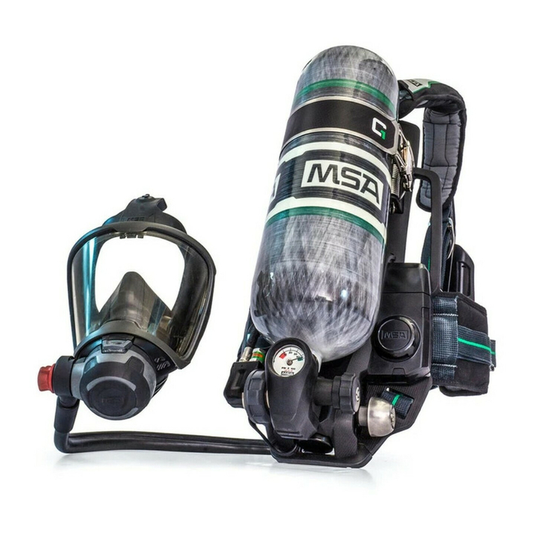
BlackHawk MMR breathing apparatus consists of the fol-
lowing major sub-assemblies.
•first stage regulator
• second stage regulator
•air cylinder and valve
• NightFighter Heads-Up Display System
• carrier and harness
• facepiece
FIRST STAGE REGULATOR
The first stage regulator is a "balanced-type’’ pressure
reducer that keeps the pressure to the mask mounted
regulator at approximately 80psig throughout the entire
operating pressure range of the cylinder. The regulator
uses a large sintered filter which is easy to replace. The
filter captures particulates that may be in the air stream.
SECOND STAGE REGULATOR
This is a pressure-demand regulator, which keeps a posi-
tive pressure in the facepiece all the time. The release
button on top of the regulator stops air flow. To stop air
flow, push the button IN. To restart the regulator, inhale
sharply. The regulator attaches to the facepiece with a
push-to-connect connector or slide connector. The regu-
lator delivers large flow rates accurately and quickly.
Blackhawk SCBA with the Firehawk MMR model numbers
10060982 and 10060983 are considered by MSA to be
“CBRN hardened”. They can be identified by the Firehawk
Regulator model number and the CBRN marking on the
underside of the regulator housing. SCBA with these reg-
ulator model numbers have passed CBRN live agent test-
ing, but are not CBRN-approved by NIOSH, since they are
not certified as NFPA compliant. MSA has chosen not to
seek NFPA compliance due to the requirement for a
redundant low-pressurewarning device, a potential safety
concernin revealing the position of the user during tacti-
cal operations.
AIR CYLINDER AND VALVE
The air cylinder and valve consists of a tank and a cylin-
der valve assembly. The cylinder valve includes a valve
body,cylinder valve inlet tube, handwheel, safety disc
(burst disc), and pressure gauge. The pressure gauge
shows the air pressure in the cylinder continuously. The
gauge is calibrated in 100psig increments. For example, a
gauge reading of 20 is read as 20 x 100 or 2,000psig. A
handwheel is used to open and close the cylinder valve.
*as approved by NIOSH
QUICK-FILL SYSTEM (OPTIONAL)
The Quick-Fill System is a shoulder mounted male quick-
fill inlet for 2216psig emergency filling of SCBA. Also
included with the 2216psig Quick-Fill System is a pres-
sure relief valve for protection of the cylinder burst disc.
The Quick-Fill System may also be used for transfill oper-
ations.
5TAL 601 (L) Rev. 5 - 10041214
WARNING
Capacity Pressure Rated Svc*
Cubic Ft. psig Life (Min.)
45 2216 30
45 4500 30
66 4500 45
88 4500 60

DESCRIPTION
CARRIER AND HARNESS
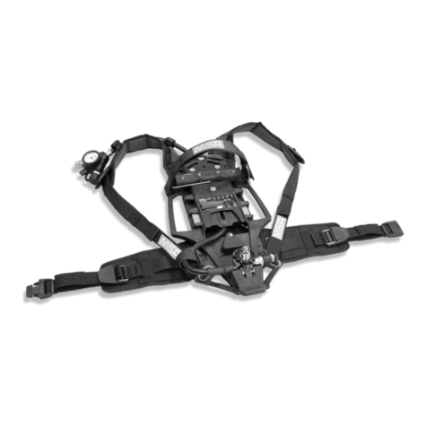
The carrier consists of a backplate, a shroud to cover the
cylinder and first stage regulator, a cylinder strap with
buckle to hold the cylinder, and a harness, consisting of
shoulder straps, chest strap (optional), adjustable pull-
straps waist-strap, shoulder pads (optional), and belt
mounted regulator retainer.
LUMBAR PAD (OPTIONAL)
The lumbar pad with a flared design is designed to pro-
vide a cushion between the wearer and harness. The
flared design evenly distributes cylinder weight across the
wearer’s hips.
FACEPIECE
The facepiece is available in three sizes. The facepiece
has a low-resistance, pressure-demand exhalation valve
designed for easy cleaning. An inhalation check valve in
the inlet housing keeps moisture and contaminants out of
the mask mounted regulator.The facepiece has a speak-
ing diaphragm for clear,shortrange communication.
Only Ultra Elite Hycar facepieces (model numbers 7-935-
7, 7-935-8, and 7-935-9) have been tested against and
meet CBRN live agent test requirements. Silicone face-
pieces are NOT CBRN approved.
NIGHTFIGHTER HEADS-UP DISPLAYSYSTEM
NightFighter Heads-Up Display System is approved intrin-
sically safe and conforms to UL/ANSI 913 for use in Class
I, Div. I, Groups A thru D hazardous locations, temperature
rating T4.
• The NightFighter Heads-Up Display System allows a
user to clearly and easily see air cylinder volume while
wearing a NFPA compliant SCBA.
• The NightFighter Heads-Up Display System allows a
user to transfer the receiver from Ultra Elite Facepiece to
another NFPA1981, 2002 Edition Ultra Elite Facepiece
Note: The NightFighter Heads-Up Display System can
only be used with an Ultra Elite Facepiece.
• The NightFighter Heads-Up Display System consists
of three (3) separate assemblies.
o Bracket assembly attached to an Ultra Elite
Facepiece.
oReceiver mounted on the bracket assembly.
oTransmitter assembled to the gauge line. (See
Installation Instruction P/N 10035581).
• The NightFighter Heads-Up Display System's Receiver
shows the user the air cylinder content in one quarter
cylinder increments, from a full cylinder to an empty
cylinder, by a LED light logic pattern.
• The NightFighter Heads-Up Display System's
Transmitter is assembled to the gauge line hose. The
transmitter sends a signal to the receiver (on the face-
piece) of the air cylinder content.
• The NightFighter Heads-Up Display System's Receiver
has seven (7) LED light patterns. (See Chart).
• The NightFighter Heads-Up Display System's Receiver
has a light sensor that automatically adjusts the
brightness of the LED based on the ambient light lev-
els measured outside of the facepiece.
• The NightFighter Heads-Up Display System's Receiver
will indicate a low battery by a Yellow LED light for the
receiver and transmitter. (See Chart).
The NightFighter Heads-Up Display System operates
using two (2) standard AAA alkaline batteries in the trans-
mitter and two (2) standard AA batteries in the receiver.
The NightFighter Heads-Up Display System notifies the
user when the batteries need to be replaced.
Use only Duracell MN2400, Energizer E92, or Eveready
A92 AAA alkaline batteries in the TRANSMITTER. Use
of other batteries, or a combination of batteries from
different manufacturers, will affect performance of unit
and will void the Intrinsic Safety approval.
Use only Duracell MN1500 or Energizer E91 AA alka-
line batteries in the RECEIVER. Use of other batteries,
or a combination of batteries from different manufac-
turers, will affect performance of unit and will void the
Intrinsic Safety approval.
Failure to follow the above warnings can result in seri-
ous personal injuryor death.
Note: For older versions of the Nightfighter RECEIVER
containing AAA Alkaline batteries, use only Duracell
MN2400, Energizer E92, or Eveready A92. Use of other
batteries, or a combination of batteries from different
manufacturers, will affect performance of unit and will
void the Intrinsic Safety approval.
Note: With system pressurized, quick press the operation
button on the transmitter. The transmitter will show cur-
rent pressure for ONLY 10 seconds.
•The LED lights in the receiver will automatically adjust
for the brightness outside of the facepiece.
• The receiver will indicate a Yellow LED light, after
going through the start-up sequence, if a low battery
condition is detected in the receiver or transmitter
(See Low Battery Warnings).
6
TAL 601 (L) Rev. 5 - 10041214
DESCRIPTION
NightFighter Heads-Up Display System Chart
The Nightfighter Heads-Up Display System illuminates a
Red LED when there is approximately 25% of the SCBA’s
rated service time remaining. The Nightfighter Heads-Up
Display System also illuminates when the cylinder valve is
first opened, providing a visual indication that the alarm is
functioning.
*as approved by NIOSH
This air mask does not have an audible alarm indica-
tor for low cylinder pressure. The NightFighter Heads-
Up Display System illuminates a Red LED light as an
indicator that the cylinder pressure is low. Failure to
return to fresh air when the red light illuminates may
result in serious personal injury or death.
Low Battery Warnings
Note: There are different low battery warnings.
• If there is a low battery in the receiver, single Yellow
LED flash.
• If there is a low battery in the transmitter, double short
Yellow LED flashes.
• If there are low batteries in the receiver and transmit-
ter, the Yellow LED will alternate single and double
flashes.
The receiver will show air cylinder volume in 25% tank
increments from full to empty. (See Chart).
7TAL 601 (L) Rev. 5 - 10041214
Approx. 25% Remaining
Cylinder Service Time
30-min. 2216 psig 7 min.
30-min. 4500 psig 7 min.
45-min. 4500 psig 11 min.
60-min. 4500 psig 14 min.
WARNING
R
GG
G
Y
G
G
G
G
Y
76% to 100%
Full Cylinder, 4 Green LED
20 Sec. Steadily ON
75% to 51%
3/4 Full Cylinder, 3 Green LED
20 Sec. Steadily ON
51% to 26%
1/2 Full Cylinder, 2 Yellow LED
30 Sec. Flashing ON/OFF
25% to 0%
1/4 Full Cylinder, 1 Red LED
Flashing Continuously
Yellow Light
Low Battery LED for
Receiver/Transmitter
Y
NOT USED

NOTES
8
TAL 601 (L) Rev. 5 - 10041214
DONNING
DONNING THE AIR MASK
1. Remove the facepiece from the case.
DoNOT use a cover lens in a high-temperature envi-
ronment. High temperatures may distort the cover
lens. Or, moisture trapped between a cover lens and
the facepiece lens may condense and distort vision.
Always remove the cover lens before donning the
facepiece.
2. Check that the cylinder is fully pressurized.
Do NOT use a partially full cylinder. If the cylinder is
not full, the service time is reduced accordingly. Do
refill cylinder valve before using the air mask.
3. Reach inside the right shoulder straps and grasp the
NightFighter Heads-Up Display System Transmitter.
Slide left arm through left shoulder straps.
4. Bend forward slightly, rest it on your back.
5. Attach the chest strap (optional).
6. Fasten the waist-strap and pull it tight for a snug fit.
7. As you straighten up, pull the shoulder strap tabs out.
Hike the unit up for a comfortable fit.
8. The shoulder straps and waist-strap ends must be
tucked in and lay flat across the body.
NIGHTFIGHTER HEADS-UP DISPLAYSYSTEM AND
REGULATOR CHECKS
1. Grasp the mask mounted regulator and push the top
release button.
2. Check that the red
bypass knob is fully
closed (clockwise).
3. Reach behind and
open the cylinder valve
fully.
Note: The NightFighter Heads-Up Display System
Receiver and Transmitter must be no more than15 inches
apart, otherwise the receiver’s LEDs may not function.
Test the NightFighter Heads-Up Display System for
damage and be sure the system operates properly
beforeeach use of the SCBA. Do NOT use this device
unless it passes all operational tests. Failure to follow
this warning can result in serious personal injury or
death.
4. Looking through the facepiece lens at the NightFighter
Heads-Up Display System Receiver, the LEDs must
illuminate in accordance with the NightFighter Heads-
Up Display System start-up sequence.
NightFighter Heads-Up Display System Start-up
Sequence
• Four Green LEDs for 20 seconds, Steadily ON.
• Three Green LEDs for 20 seconds, Steadily ON.
• Two Yellow LEDs for 30 seconds, Flashing
Continuously.
• One Red LED, Flashing Continuously.
• Yellow LED for Low Battery.
Note: If the NightFighter Heads-Up Display System con-
tinues to show a Yellow LED after going through the start-
up sequence, it is necessary to replace the receiver
and/or transmitter batteries prior to using the SCBA (See
Low Battery Warnings and Battery Replacement).
5. Check for regulator
leakage. No air should
flow from the regulator.
If it does, repeat steps
1and 2.
9TAL 601 (L) Rev. 5 - 10041214
WARNING
CAUTION
WARNING

DONNING
6. Check for bypass oper-
ation. Grasp the red
knob and turn it
counter-clockwise.
Listen for air flow.
Close the bypass.
There must be a continuous flow of air when the
bypass knob is opened. If not, do not use the appara-
tus. The SCBA must be checked and corrected for
proper operation by an MSA trained or certified repair-
person before using it. Failure to follow this precaution
may result in serious personal injuryor death.
LEAK AND NIGHTFIGHTER HEADS-UP DISPLAY SYS-
TEM CHECKS
Note: Continuous Operations Mode can only be activated
when SCBA is pressurized.
1. Place NightFighter Heads-Up Display System into
Continuous Operations Mode. Press and hold
Operation Button on transmitter for 3 seconds. Once
LEDs come on, release button.
2. Close the cylinder valve fully.
3. Watch the NightFighter Heads-Up Display System
Receiver for 60 seconds. The LED light patternmust
not change.
If the NightFighter Heads-Up Display System
Receiver’s LED light pattern changes, do not use the
apparatus. The SCBA must be checked and corrected
for proper operation by an MSA trained or certified
repairperson beforeusing. Failureto follow this pre-
caution may result in serious personal injury or death.
4. Crack the bypass valve slowly to bleed off pressure.
5. Watch the NightFighter Heads-Up Display System
Receiver while bleeding off pressure. The LEDs must
illuminate in accordance with the NightFighter Heads-
Up Display System decreasing pressure sequence.
NightFighter Heads-Up Display System Decreasing
PressureSequence
• Four Green LEDs, Steadily ON.
• Three Green LEDs, Steadily ON.
•Two Yellow LEDs, Flashing Continuously.
• One Red LED, Flashing Continuously.
If the NightFighter Heads-Up Display System fails to
illuminate in the decreasing pressure sequence, do not
use the SCBA. The SCBA must be checked and cor-
rected for proper operation by an MSA trained or cer-
tified repairperson before using. Failure to follow this
precaution may result in serious personal injury or
death.
Note: The NightFighter Heads-Up Display System will
automatically turn itself OFF, approximately 60 seconds
after the apparatus is depressurized. (The single Red LED
will flash at this time).
DONNING THE FACEPIECE
Do not wear eye glasses under the facepiece. The
temples or sidebars on eye glasses will prevent an air-
tight seal. If you must wear glasses, install the specta-
cle kit. Failureto follow this precaution may cause
inhalation of contaminated air, resulting in serious res-
piratory injury or death.
1. Extend the facepiece straps fully. Place neckstrap
around your neck and don the facepiece by inserting
your chin first.
2. Pull the head harness
completely over your
head.
3. Tighten the lower (neck) harness straps first, by pulling
them straight back, not out.
4. Tighten the temple
straps the same way.
Tuck in the ends of the
straps so that they lay
flat across the head.
10
TAL 601 (L) Rev. 5 - 10041214
WARNING
WARNING
WARNING
WARNING

DONNING
5. Push headband pad towards neck, retighten the
straps (if necessary) for best visibility and fit. Tuck in
the ends of the straps so they flat across the head.
FACEPIECE FIT CHECK
Check the inhalation valve, inhale. If you do not
receive sufficient flow of air, do not use facepiece. The
facepiece must be repaired or replaced. Failure to fol-
low this precaution can result in serious personal
injury or death.
1. To check for facepiece
fit, hold the palm of
your hand over the inlet
connection and inhale.
Hold your breath at
least 10 seconds. The
facepiece should col-
lapse and stay col-
lapsed against your
face. If it does not,
readjust the facepiece
and test again. If this
does not correct the leak, do not use the facepiece.
2. Test the exhalation
valve, take a deep
breath and hold it.
Block the inlet connec-
tion with the palm of
your hand and exhale.
If the exhalation valve
is stuck, you may feel a
heavy rush of air
around the facepiece.
Note: You may need to exhale sharply to open the valve.
If this does not release the valve, do not use the face-
piece.
This device may not seal properly with your face if you
have a beard, gross sideburns, or similar physical
characteristics (see NFPA-1500 and ANSI Z88.2). An
improper facial seal may allow contaminants to leak
into the facepiece, reducing or eliminating respiratory
protection. Do not use this device if such conditions
exist. The face-to-facepiece seal must be tested
before each use. Never remove the facepiece except
in a safe, non-hazardous, non-toxic atmosphere.
3. Open the cylinder valve
fully.
4. Place NightFighter Heads-Up Display System into
Continuous Operations Mode. Press and hold
Operation Button on transmitter for 3 seconds. Once
LEDs come on, release button.
Note: The Continuous Operations Mode will deactivate if
alow battery condition is present.
INSTALLING PUSH-TO-CONNECT
MASK MOUNTED REGULATOR
Note: Beforedonning, check that the regulator sealing
ring is seated properly in its groove, and that it is not torn,
gouged, or nicked.
1. Grasp regulator and
orient regulator so that
red bypass knob is
pointing to the right.
2. Insert regulator into
facepiece adapter by
pushing inward.
3. Ensure the regulator locks into facepiece.
4. Check proper engagement by pulling on the regulator
to ensure regulator is securely attached to facepiece.
11 TAL 601 (L) Rev. 5 - 10041214
WARNING
WARNING

DONNING
Do not use the respirator unless the regulator is con-
nected properly. A regulator that is not installed cor-
rectly can separate from the facepiece unexpectedly.
Return the respirator to an MSA trained or certified
repairperson to correct the condition. Failure to follow
this precaution can result in serious personal injury or
death.
5.Inhale sharply to start the air flow.
a. Check the bypass again by turning the red knob
counter-clockwise until you feel increased air flow.
Close the bypass.
There must be a continuous flow of air when the
bypass knob is opened. If not, do not use the appara-
tus. The SCBA must be checked and corrected for
proper operation by an MSA trained or certified repair-
person before using it. Failure to follow this precaution
may result in serious personal injuryor death.
Note: If the air mask passes all tests, the unit is ready to
use. Remember, you must perform these tests every time
before you enter the hazardous atmosphere. If the unit
fails to meet any of the tests, the condition(s) must be
corrected before using the apparatus.
PRECAUTIONS DURING USE
• Be sure the NightFighter Heads-Up Display System is
in Continuous Operations Mode.
• Periodically check the pressure on the NightFighter
Heads-Up Display System.
• When the NightFighter Heads-Up Display System
starts flashing a Red LED, immediately returnto fresh
air.
Note: Air mask service life is reduced greatly when the
bypass is used.
• Reduced air flow: Immediately open the
bypass.
Immediately return to fresh
air.
• Air mask free-flows: Immediately return to fresh
air.
•NightFighter Heads-Up Immediately returnto fresh
Display System flashes air.
areturn to Red LED:
INSTALLING SLIDE MASK MOUNTED REGULATOR
1. Grasp regulator and orient regulator so that red
bypass knob is pointing to the right and slide button is
on top.
2. Slide regulator onto rail (fast track) of facepiece cover.
Slide regulator down the rail cover until regulator
stops.
3.Insert regulator into facepiece adapter by pushing
inward.
4. Ensure the regulator locks into facepiece.
5. Check proper engagement by pulling on the regulator
to ensure regulator is securely attached to facepiece.
Do not use the respirator unless the regulator is con-
nected properly. A regulator that is not installed cor-
rectly can separate from the facepiece unexpectedly.
Return the respirator to an MSA trained or certified
repairperson to correct the condition. Failure to follow
this precaution can result in serious personal injuryor
death.
1. Inhale sharply to start the air flow.
a. Check the bypass again by turning the red knob
counter-clockwise until you feel increased air flow.
Close the bypass.
There must be a continuous flow of air when the
bypass knob is opened. If not, do not use the appara-
tus. The respirator must be checked and the condition
corrected by an MSA trained or certified repairperson
before using it. Failure to follow this precaution may
result in serious personal injury or death.
Note: If the air mask passes all tests, the unit is ready to
use. Remember, you must perform these tests every time
before you enter the hazardous atmosphere. If the unit
fails to meet any of the tests, the condition(s) must be
corrected before using the apparatus.
12
TAL 601 (L) Rev. 5 - 10041214
WARNING
WARNING
WARNING
WARNING

REMOVING THE APPARATUS
DISCONNECTING THE PUSH-TO-CONNECT
REGULATOR
1. Grasp top of regulator.
2. Push the release but-
tons and pull regulator
down and out of face-
piece adapter.
3. Close the cylinder valve
fully. Open the bypass
to release system pres-
sure. Close the bypass.
4. The NightFighter Heads-Up Display System will auto-
matically turn itself OFF, approximately 60 seconds
after the apparatus is depressurized. (The single Red
LED light will flash at this time.)
5. Stow the regulator with
red bypass knob point-
ing to the right in the
stand-by belt mount.
6. To remove the face-
piece, fully loosen the
harness straps and pull
the facepiece up and
away from your face.
7. To remove the carrier harness, press the belt buckle
release buttons IN.
8. Disconnect the chest strap (if used).
9. To loosen the shoulder straps, grasp the release tabs.
Push them out and away from your body.
10. Slip your right arm out of the shoulder strap first, then
remove the harness.
Note: Be sure to replace the cylinder with a full one.
Complete Inspection and Cleaning and Disinfecting pro-
cedures outlined in this manual. Ensure complete appara-
tus is clean and dry. Ensure that facepiece head harness
straps and harness adjustment straps are fully extended.
Place the complete apparatus in the storage case or suit-
able storage location so it can be reached easily for emer-
gency use. (See storage instructions.)
DISCONNECTING THE SLIDE REGULATOR
1. Grasp top of regulator.
2. Push the release buttons and pull regulator down and
out of facepiece adapter.
Note: Regulator can hang on cover rail in a stand-by
mode.
3. Slide regulator up cover rail until regulator slide button
is free of cover rail.
4. Close the cylinder valve fully.Open the bypass to
release system pressure.
5. The Nightfighter Heads-Up Display System will auto-
matically set itself OFF
,approximately 60 seconds
after the apparatus is depressurized. (The single Red
LED light will flash at this time.)
6. Stow the regulator with red bypass knob pointing to
the right in the stand-by belt mount.
7. To remove the facepiece, fully loosen the harness
straps and pull the facepiece up and away from your
face.
8. To remove the carrier harness, press the belt buckle
release button IN.
9. Disconnect the chest strap (if used).
10. Toloosen the shoulder straps, grasp the release tabs.
Push them out and away from your body.
13 TAL 601 (L) Rev. 5 - 10041214

REMOVING THE APPARATUS
11. Slip your right arm out of the shoulder pad first, then
remove the harness.
Note: Be sure to replace the cylinder with a full one.
Complete Inspection and Cleaning and Disinfecting
Procedures outlines in this manual. Ensure complete
apparatus is clean and dry. Ensure that facepiece head
harness straps and harness adjustment straps are fully
extended. Place the complete apparatus in the storage
case or suitable storage location so it can be reached
easily for emergency use. (See storage instructions.)
CHANGING THE CYLINDER
REMOVING THE SHROUD
1. Unsnap the bottom two retaining straps.
2. Extend bottom left side of shroud and remove shroud
from first stage regulator.
3. Slide shroud off the cylinder valve handwheel.
4. Fold shroud over the
top of cylinder, expos-
ing the cylinder fully.
CYLINDER CHANGE OUT
Be careful not to drop cylinder or bump valve knob. An
unsecured cylinder can become an airborne projectile
under its own pressure if the valve is opened even
slightly.
1. Be sure there is no pressure in the system before
replacing a cylinder.Disconnect the coupling nut.
2. Lift over center buckle to loosen the cylinder strap.
3. Slide out the empty cylinder and install one that is fully
charged. Be sure that the adjustable cylinder buckle is
properly adjusted.
4. Slide the fully charged cylinder into the carrier, with
gauge facing out, pull the over center strap and buck-
le to tighten the cylinder strap.
5. To check that the cylinder is secure, place one hand
on the backplate and grasp the cylinder valve with the
other. Tryto pull the cylinder and valve down and out
away from the carrier. Make sure that the strap and
buckle hold the cylinder securely in the carrier.
Note: If the cylinder feels loose, re-check that the strap
and buckle are properly adjusted. Open cylinder buckle.
Tighten cylinder strap by pulling on top (outer) strap. It will
be necessary to reposition the black plastic slide during
adjustment. Tighten cylinder strap until cylinder buckle is
approximately 45 degrees from vertical. Close the cylinder
buckle. Do not use the air mask if the cylinder is not held
securely in the carrier.
Do NOT over-tighten the cylinder strap; otherwise it
will damage the center buckle assembly.
6. Check that the O-ring is inside the coupling nut. If the
O-ring is damaged it must be replaced before the
alarm is used.
7. Thread the coupling nut to the cylinder valve and
hand-tighten (no tools).
RE-ATTACHING THE SHROUD
1. Slide shroud down over cylinder.
2. Slide cylinder valve handwheel through the bottom
slot of shroud.
3. Extend bottom left side of shroud over first stage reg-
ulator.
4. Snap the bottom two retaining straps.
CHARGING CYLINDERS
1. Remove from service if cylinder shows evidence of
exposure to high heat or flame: e.g., paint turned
to a brown or black color, decals charred or miss-
ing, gauge lens melted, or elastomeric materials
distorted.
2. Use this device only after receiving proper training
in its use. Use in accordance with this label and
MSA apparatus instructions.
3. To maintain NIOSH approval, container must be
fully charged with respirable air meeting the
requirements of the Compressed Gas Association
specification G-7.1 1989 for Quality Verification
Level (grade) D air or equivalent specification.
4. Do not use unless the cylinder is filled to the full
pressureapproved.
5. Do not alter, modify or substitute any components
without approval of the manufacturer.
6. Inspect frequently. Maintain according to manufac-
turer’s instructions. Repair only by properly trained
personnel.
Failure to comply with these warnings can result in
serious personal injury or death.
14
TAL 601 (L) Rev. 5 - 10041214
WARNING
CAUTION
WARNING

REMOVING THE APPARATUS
SAFETY PRECAUTIONS FOR MSA SELF-CONTAINED
BREATHING APPARATUS CYLINDERS
Breathing apparatus cylinders should be fully recharged
as soon as practicable after use. Cylinders should not be
stored partially charged for two reasons:
1.If used partially charged, the duration of the apparatus
isreduced.
2. The pressure relief device is only designed to protect
afully charged cylinder from the effects of a fire.
For maximum safety, the cylinders should be stored full or
at a pressure above ambient but less than 100psig. Prior
to recharged, cylinders must be examined externally for
evidence of high heat exposure, corrosion, or other evi-
dence of significant damage.
Additional information of value when performing external
and internal inspections of cylinders may be found in the
latest editions of CGA Publication C-6: "Standards for
Visual Inspection of Steel Compressed Gas Cylinders",
CGA Publication C-6.1: "Standards for Visual Inspection
of High Pressure Aluminum Compressed Gas Cylinders",
and/or CGA Publication C-6.2: "Guidelines for Visual
inspection and Requalification of Fiber Reinforced High
Pressure Cylinders" available form the Compressed Gas
Association, Inc., 1725 Jefferson Davis Highway, Suite
1004, Arlington, VA22202-4102.
If thereis any doubt about the suitability of the cylinder
for recharge, it should be returned to a certified hydrostat-
ic test facility for expertexamination and testing.
Always check to be sure the retest date is within the pre-
scribed period and that the cylinder is properly labeled to
indicate its gaseous service. New labels are restricted
items which are not available except through certified
hydrostatic test facilities.
When replacing cylinder valves or after the retesting of
cylinders, make sure the proper cylinder valve, burst disc,
and O-ring are installed prior to cylinder recharging.
Establish the service pressure of the cylinder. All cylinders
shall be filled to the designated service pressure only (as
found on the DOT approval or stamping). For cylinders
manufactured under a U.S. DOT exemption (i.e., DOT-E-
#####), the exemption should be consulted and is avail-
able from the Associate Administrator for Hazardous
Materials Safety, Research and Special Programs
Administration, U.S. Department of Transportation, 400
7th Street, SW, Washington, D.C. 20590-0001.
Appropriately connect the cylinder to the filling system
and refill. Terminate the filling when the pressure reaches
the service pressure and allow the cylinder to cool to
room temperature. If necessary, top-off the cylinder such
that the service pressure is attained with the cylinder at a
temperature of 70°F. Close the valves on the cylinder and
the filling system and remove the cylinder. Apply a leak
solution to determine if there is any leakage between the
cylinder and the valve. If there is no leakage, the cylinder
is ready for use.
STORAGE
Do not store the apparatus or spare cylinders within or
near an area where the apparatus can or might be
exposed to any substances that will or might attack any
part of the apparatus, causing the apparatus NOT to per-
form as designed and approved.
Be careful not to drop cylinder or bump valve knob. An
unsecured cylinder can become an airborne projectile
under its own pressure if the valve is opened even
slightly. Failure to follow this precaution may result in
serious personal injury or death.
Do not store the NightFighter Heads-Up Display System
with the batteries installed. Do not storethe apparatus
with an empty or partly filled cylinder.Always install a ful-
lycharged cylinder so that the apparatus is ready for use.
Complete Inspection and Cleaning and Disinfecting
Procedures outlined in this manual. Ensure the complete
apparatus is clean and dry. Ensure the facepiece head
harness adjustment straps are fully extended. Place the
complete apparatus in the storage case or suitable stor-
age location so it can be easily reached for emergency
use.
Tostore the NightFighter Heads-Up Display System com-
ponents, be sure that the unit is in the OFF (LED is not
illuminated) position. Remove the batteries to prevent bat-
tery corrosion. Store units in a cool, dry place.
BATTERY REPLACEMENT
In continuous service, battery life will vary depending on
user conditions. The battery is not rechargeable.
Use only Duracell MN2400, Energizer E92, or Eveready
A92 AAA alkaline batteries in the TRANSMITTER. Use
of other batteries, or a combination of batteries from
different manufacturers, will affect performance of unit
and will void the Intrinsic Safety approval. Failure to
follow this warning can result in serious personal
injuryor death.
1. Unfasten transmitter shroud strap(s).
2. Slide shroud off transmitter to expose battery door
screws.
15 TAL 601 (L) Rev. 5 - 10041214
WARNING
WARNING

REMOVING THE APPARATUS
3. Loosen the screws to open battery door.
4. Insert two AAA batteries according to the battery ori-
entation noted inside the compartment.
5. Close the battery door and tighten the screws.
6. Slide shroud over transmitter and fasten strap(s).
Use only Duracell MN1500 or Energizer E91 AA alka-
line batteries in the RECEIVER. Use of other batteries,
or a combination of batteries from different manufac-
turers, will affect performance of unit and will void the
Intrinsic Safety approval. Failure to follow this warning
can result in serious personal injury or death.
Note: For older versions of the Nightfighter RECEIVER
containing AAA Alkaline batteries, use only Duracell
MN2400, Energizer E92, or Eveready A92. Use of other
batteries, or a combination of batteries from different
manufacturers, will affect performance of unit and will
void the Intrinsic Safety approval.
1. Loosen the screws to open the battery door in the
receiver.
2. Insert two AA batteries according to the battery orien-
tation noted inside the receiver compartment.
3. Inspect the battery cover gasket is free of debris and
not damaged or missing.
4.Close the battery door and tighten the screws.
Battery Disposal/Recycling
Dispose of or recycle batteries in accordance with all
applicable federal, state, and local regulations.
Do not dispose of the battery in fire. It may explode.
Failure to follow this warning can result in serious per-
sonal injury or death.
16
TAL 601 (L) Rev. 5 - 10041214
WARNING
WARNING

QUICK-FILL SYSTEM OPERATION
The Quick-Fill is a male quick-fill inlet for use by Rapid
Intervention Crews for emergency filling operations. The
2216psig system also includes an automatically-resetting
pressure relief valve.
Note: The Quick-Fill may be used for transfill operations
asdescribed in this manual. Standard operating proce-
dures should be developed for use of Quick-Fill System.
The Quick-Fill System must be used only by qualified,
trained personnel who have carefully read and understood
these instructions, cautions, and warnings. NIOSH
approvals of SCBA from MSA are maintained while trans-
filling air ONLY if appropriate Quick-Fill hose assemblies
from MSA are used. Quick-Fill hose assemblies and fittings
are rated for a maximum working pressure of 4500psig.
For transfilling operations using the Quick-Fill System,
do not use any transfilling hose assembly or fittings
other than those supplied by MSA specifically for the
Quick-Fill System. Use of any other transfilling hose
assembly and/or fitting may result in serious personal
injuryor death, and will void NIOSH approval.
Do not lubricate the Quick-Fill fittings. Do not permit
oil, grease, or other contaminants to come in contact
with the Quick-Fill fittings. The Quick-Fill hose assem-
blies and fittings are designed to be used with Quality
Verification Level (Grade) D or better air as defined by
ANSI/CGA G-7.1.
TRANSFILLING AIR FROM A SECONDARY AIR SOURCE
Asecondary air source stores compressed breathing air
until needed to refill SCBA air cylinders. Secondary air
source pressure must be greater than air mask cylinder
pressure. Examples of air sources include: Cascade air
cylinder refilling systems; high pressurecompressor sys-
tems with a fixed reservoir; and an SCBA air cylinder
which is not installed on an SCBA.
Do not connect a Quick-Fill System equipped Low
Pressure SCBA to an unregulated secondary air
source with a pressure greater than 2216psig. The
Quick-Fill System equipped low pressureair mask is
rated for a maximum working pressure of 2216psig. As
an additional safety feature, the SCBA has a pressure
relief valve which automatically vents at 2500psig. Do
not connect a High PressureSCBA to a secondaryair
source with a pressure greater than 4500psig. The
high pressure air mask is rated for a maximum work-
ing pressure of 4500psig.
Failure to follow the above warnings may result in
serious personal injury or death.
The user is responsible for the air source, which must
meet the requirements of Compressed Gas Association
Specification ANSI/G-7.1, Quality Verification Level
(Grade) D Gaseous Air or better, with a moisture dew
point of not greater than -65°F (24ppm water vapor, nor-
mal). Pressures at the inlet of the Quick-Fill System hose
must not exceed that of the SCBA (2216psig or
4500psig). The user also is responsible for connecting the
Quick-Fill hose to an appropriate secondary air source.
1. To connect the Quick-Fill System hose to Quick-Fill
System fitting installed on the air source):
a. Push the female fitting on the male fitting until it
snaps in place. Pull on the hose to be sure the fit-
ting snapped into place.
b. Turn the air source on.
If there are leaks from either female fitting, or along
the hose, depressurize the hose and correct the prob-
lem. Such leakage can result in increased fill time.
2. To attach the Quick-Fill System hose to the SCBA:
a. Remove the rubber dust cap from the male inlet fit-
ting on the SCBA. Be surethat the cylinder valve is
fully opened.
Note: The shut-off button may be either open or closed,
depending on whether the SCBA is donned.
b. Remove the rubber dust cap from the female fitting
on the Quick-Fill System hose.
c. Push the female fitting on the male fitting until it
snaps in place. Pull on the hose to be sure the fit-
ting snapped into place. Transfilling begins when
the female fitting is snapped on the SCBA.
Note: If the secondary air source does not have a suffi-
cient volume of air, the SCBA cylinder will not reach full
service pressure. After approximately 45-60 seconds,
pressure between the secondary air source and the SCBA
cylinder will be equal.
Cylinder temperature will increase by approximately
45°F
.The pressure gauge may show FULL immediately
after transfilling, but cylinder pressure may decrease
by as much as 190psig after the cylinder cools to
room temperature. Actual service time may be
reduced accordingly.
3. Compare the SCBA pressure gauge reading to the
secondaryair source pressure gauge reading. If the
readings are the same, pressure is equal.
4. Todisconnect the Quick-Fill System hose after trans-
filling, pull the gray sleeve back. The hose fitting and
17 TAL 601 (L) Rev. 5 - 10041214
WARNING
WARNING
CAUTION

QUICK-FILL SYSTEM OPERATION
the SCBA will separate. A hiss or pop may be heard
as the fittings separate and the high-pressure air is
sealed off.
5. Immediately install the dust cover on the SCBA male
fitting.
6. The SCBA cylinder is ready for service if the cylinder
pressure gauge is on the corresponding color band.
EMERGENCY OPERATIONS
1. If you are transfilling in fresh air and the dust cover will
not stay on the SCBA male fitting because air is leak-
ing, correct the condition before using the SCBA.
2. If you are transfilling in a contaminated atmosphere
and the dust cover will not stay on the SCBA male fit-
ting because air is leaking:
a. Immediately reconnect the Quick-Fill System hose
to seal off the leak and return to fresh air.
b. If you cannot reconnect the hose, reach behind and
close the cylinder valve. Air pressure in the regulator
will drop, and the leak will slow down.
c. Quickly replace the protective dust cap on the
SCBA male regulator fitting. This will form a redun-
dant seal.
d. Open the cylinder valve and returnto fresh air
immediately. The dust cover prevents dirt, water,
and debris from entering the fitting, and acts as a
redundant seal.
TRANSFILLING BETWEEN SCBA FROM MSA
(EMERGENCY BREATHING SYSTEM)
Note: The SCBA with the higher pressure reading is the
donor. The SCBA with the lower pressure is the receiver.
Transfilling between users of SCBA should be performed
only during life-threatening emergencies, or simulated
training exercises. Both donor and receiver must return to
fresh air immediately following the procedure.
Do not transfill if the donor's NightFighter Heads-Up
Display System is flashing. Failure to follow this warn-
ing may result in shorter escape time to return to fresh
air,causing serious personal injuryor death.
NIGHTFIGHTER HEADS-UP DISPLAY SYSTEM
RECEIVER PRESSURE READING
The NightFighter Heads-Up Display System Red LED
begins flashing to indicate that the pressure in the cylinder
has been reduced to 25% of its rated working pressure.
Remaining service time must be used for escape to fresh
air. If the donor's NightFighter Heads-Up Display System
Red LED begins flashing during transfilling, the donor
should disconnect and preserve his escape time.
1. If the donor's NightFighter Heads-Up Display System
is not flashing and you have sufficient air to transfill air
to a receiver, (greater than1000psig for Low Pressure
SCBA and greater than 2000psig for High Pressure
SCBA), follow these steps.
a. Remove the 3 foot emergency transfill hose from its
protective pouch.
b. Remove the rubber dust cover from both female fit-
tings on the Quick-Fill System hose assembly.
c. Remove the rubber dust cover from the male quick-
fill fitting.
d. Push the female fittings on to the male fittings until
they click in place. Pull on the hose to be sure it
snapped in place.
If serious leakage is noticed from either of the two
female fittings, or anywhere along the hose, discon-
nect the female fittings and return to fresh air immedi-
ately.Failureto follow this warning may result in seri-
ous personal injury or death.
e. After approximately 30-60 seconds, pressure
between the SCBA cylinders will be equal.
f. Disconnect the Quick-Fill System hose from both
SCBA by pulling the gray sleeve back on both ends.
Ahiss or pop may be heardas the fittings separate
and the high pressure air is sealed off.
g. Immediately install the dust cover on the quick-fill
male fitting. The dust cover prevents dirt, water, and
debris from entering the fitting, and acts as a redun-
dant seal.
EMERGENCY OPERATIONS
1. If the dust cover will not stay on the SCBA or Quick-
Fill male fitting because air is leaking:
a. Immediately reconnect the Quick-Fill System hose
to seal off the leak and return to fresh air.
b. If you can not reconnect the hose, reach behind
and close the cylinder valve. Air pressure in the reg-
ulator will drop, and the leak will slow down.
c. Quickly replace the protective dust cap on the
SCBA male fitting. This will formaredundant seal.
d. Open the cylinder valve and return to fresh air
immediately.
2. Preparing the Quick-Fill System for Storage:
a. Press in on the center of the quick-disconnect dust
cap to release any pressure in the Quick-Fill System
hose.
b. Roll up the hose and place it in its protective pouch.
Note: Only persons trained in MSA Maintenance are
authorized to repair or disassemble the Quick-Fill System.
If repairs are required, contact your nearest MSA office.
Call 1-800-MSA-2222.
18
TAL 601 (L) Rev. 5 - 10041214
WARNING
WARNING

COLD WEATHER OPERATION
SUGGESTED PROCEDURES FOR COLD WEATHER
OPERATION
Moisture can cause problems in air masks if it freezes.
However, moisture can cause freezing problems even if
the surrounding air is above freezing. This is due to air
flowing from the cylinder through the regulator drops from
cylinder pressure to close to atmospheric pressure very
quickly. As it does so it expands, causing the air and the
regulator to become colder. Although the surrounding
temperature may be warmer than 32°F, the temperature
inside the regulator may be lower. Any water inside could
turn to ice and restrict air flow.
1. To keep moisture from entering the mask mounted
regulator. Stow the regulator in the stand-by belt
mount.
2. When the air mask is away from heat, water can
freeze on the regulator surface. Ice can build up and
freeze the buttons, bypass valve, and the release tabs.
Before entering or re-entering a hazardous atmos-
phere, make sure the buttons, release tabs, and
bypass valve are ice-free and operating properly.
Periodically, check the bypass to be sure it is ice-free.
3. Moisture can enter through the cylinder valve or cou-
pling nut when cylinders are replaced on the air mask.
When replacing cylinders, be careful to prevent mois-
ture or contamination from entering the system.
Remove any ice from these fittings. Wipe the coupling
nut threads and cylinder valve threads dry before dis-
connecting the cylinder. Water can contaminate the
system and freeze.
4. NIOSH certification requires a nosecup at tempera-
tures below 32°F. The nosecup reduces lens fogging
and must be used whenever freezing conditions are
encountered.
5. Thoroughly dry the facepiece and mask mounted reg-
ulator after cleaning and disinfecting. Follow
Confidence Plus®Cleaning Solution Instructions.
19 TAL 601 (L) Rev. 5 - 10041214

NOTES
20
TAL 601 (L) Rev. 5 - 10041214
Table of contents
Other MSA Respiratory Product manuals

MSA
MSA Advantage 200 LS User manual

MSA
MSA FSR W65 User manual

MSA
MSA FIREHAWK M7 ULTRA ELITE 10084690 Setup guide

MSA
MSA Advantage 400 Series User manual

MSA
MSA G1 SCBA User manual

MSA
MSA TransAire 10008292 User manual

MSA
MSA Advantage 200 LS User manual

MSA
MSA Ultravue P100 User manual

MSA
MSA advantage 1000 User manual

MSA
MSA PremAire Cadet Escape G1 User manual