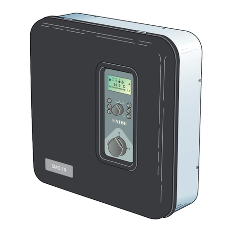
Nibe AXC 50 User guide

Installer manual
LEK
AXC 50
Accessories
IHB GB 1222-1
231158


Table of Contents
1 General 2
Contents 2
Component positions 2
2 Common electrical connection 3
Connecting the supply 3
Connecting communication 3
3 Shunt controlled additional
heat 4
General 4
Pipe connections 4
Outline diagram 5
Electrical connection 6
Program settings 7
Electrical circuit diagram 8
4 Step controlled additional
heat 9
General 9
Pipe connections 9
Outline diagram 10
Electrical connection 11
Program settings 12
Electrical circuit diagram 13
5 Extra climate system 14
General 14
Pipe connections 14
Outline diagram 15
Electrical connection 17
Program settings 18
Electrical circuit diagram 19
6 Hot water comfort 20
General 20
Pipe connections 20
Outline diagram 21
Electrical connection 22
Program settings 23
Electrical circuit diagram 24
7 Groundwater pump 25
General 25
Outline diagram 25
Electrical connection 26
Program settings 26
Electrical circuit diagram 27
8 Passive cooling (4-pipe) 28
General 28
Pipe connections 28
Outline diagram 29
Electrical connection 30
Program settings 31
Electrical circuit diagram 32
9 Passive cooling (2-pipe) 33
General 33
Pipe connections 33
Outline diagram 35
Electrical connection 36
Program settings 37
Electrical circuit diagram 38
10 Passive/active cooling (2-pipe) 39
General 39
Pipe connections 39
Outline diagram 40
Electrical connection 41
Program settings 43
Electrical circuit diagram 44
1Table of Contents |AXC 50

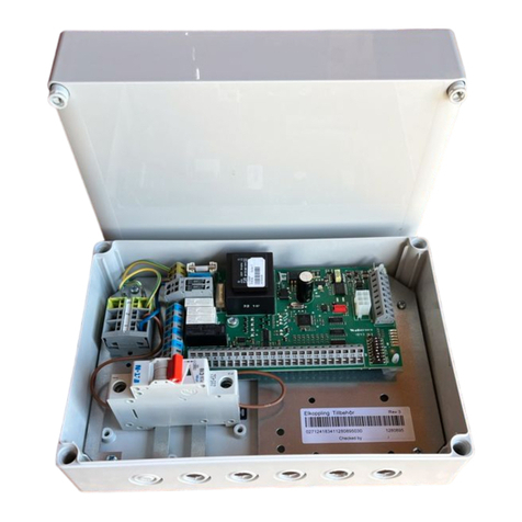
This accessory is used to enable connection and control
of (a AXC 50 is required for each of the following access-
ory functions that is used):
႑Shunt controlled additional heat
႑Step controlled additional heat
႑Passive cooling (4-pipe)
႑Passive cooling (2-pipe)
႑Passive/active cooling (2-pipe)
႑Extra climate system
႑Hot water comfort
႑Groundwater pump
Contents
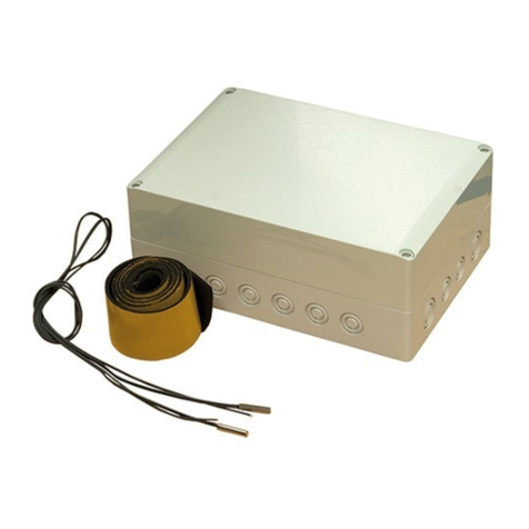
Cable ties4x
Heating pipe paste2x
Insulation tape1x
Kit for accessory card1x
Aluminium tape2x
Temperature sensor2x
Component positions
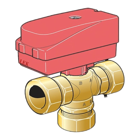
LEK
AA5-X4
AA5-S2
AA5-X2 AA5-X9 X1
FA1
AA5-F1AA5
Electrical components
Miniature circuit-breaker. 10AFA1
Terminal block, power supplyX1
Accessory cardAA5
Terminal block, sensors and external
blocking
AA5-X2
Terminal block, communicationAA5-X4
Terminal block, circulation pump, mixing
valve and auxiliary relay
AA5-X9
DIP switchAA5-S2
Fine wire fuse, T4AH250VAA5-F1
Designations in component locations according to
standard IEC 81346-1 and 81346-2.
AXC 50Chapter 1 | General2
1 General

NOTE
All electrical connections must be carried out by
an authorised electrician.
Electrical installation and wiring must be carried
out in accordance with the stipulations in force.
The heat pump must not be powered when in-
stalling AXC 50.
Electrical circuit diagrams are at the end of the chapter
for each connection option.
Connecting the supply
Connect the power supply to terminal block X1 as illus-
trated.
3
2
1N
230V 50Hz-X1
L
PE
8QLW ER[ ([WHUQDO
Connecting communication
This accessory contains an accessories card (AA5) that
must be connected directly to the heat pump on terminal
block X6 in F1345.
If several accessories are to be connected or are already
installed, the following instructions must be followed.
The first accessory card must be connected directly to the
terminal block X6 in F1345. The following cards must be
connected in series with the previous card.
Use cable type LiYY, EKKX or similar.
1
2
3
4
5
6
7
8
AA5-X4
A
B
GND
A
B
GND
A
B
GND
A
B
GND
1
2
3
4
5
6
7
8
AA5-X4
X6
1234
A
B
GND
$FFHVVRU\ FDUG
$FFHVVRU\ FDUG
ON
12345678
-X9
-X2
24 20212223 1516171819 1011121314 567891
1
N
L
PE
PE
1
2
3
4
5
6
7
8
2
3
4
5
6
7
8
9
234
-X8
-X4
-X10
-X1
$$;
ON
12345678
-X9
-X2
24 20212223 1516171819 1011121314 567891
1
N
L
PE
PE
1
2
3
4
5
6
7
8
2
3
4
5
6
7
8
9
234
-X8
-X4
-X10
-X1
$$;
(%
LEK
)
;
3Chapter 2 | Common electrical connectionAXC 50
2 Common electrical connection

General
This connection enables an external additional heater,
e.g. an oil boiler, gas boiler or district heating exchanger
to aid with heating.
The heat pump controls a shunt valve and a circulation
pump via AXC 50. If the heat pump cannot maintain the
right flow temperature the additional heating starts.
When the boiler temperature has been increased to about
55 ° C, the heat pump sends a signal to the shunt (QN11)
to open from the addition. The shunt (QN11) adjusts so
the true flow temperature corresponds with the control
system’s theoretical calculated set point value. When the
heating requirement drops sufficiently so the additional
heat is no longer required the shunt (QN11) closes com-
pletely. Minimum connection time for the boiler is 12
hours.
Pipe connections
The external circulation pump (GP10) is positioned accord-
ing to the outline diagram.
Shunt valve
The shunt valve (QN11) is located on the flow line to the
climate system after the heat pump according to the
outline diagram.
AB
B
A
႑Connect the flow line from the heat
pump to the external heat source via
the T-pipe to port B on the shunt
valve (closes at reduced signal).
႑Connect the flow line to the climate
system from the shunt valve to the
common port AB (always open)
႑Connect the flow line from the external additional heat
to the shunt valve to port A (opens at increased signal).
Temperature sensor
႑Install the boiler sensor (BT52) in a suitable location in
the external addition.
႑External flow temperature sensor (BT25, connected in
F1345) must be installed on the flow line to the radiat-
ors, after the shunt valve (QN11).
K
Install the temperature sensors with cable ties with the
heat conducting paste and aluminium tape. Then insulate
with supplied insulation tape.
NOTE
Sensor and communication cables must not be
placed near power cables.
AXC 50Chapter 3 | Shunt controlled additional heat4
3 Shunt controlled additional heat

Outline diagram
Explanation
Heat pump system (Master)EB100
Temperature sensor, outdoorBT1
Temperature sensor, hot water chargingBT6
Temperature sensor, heating medium flow,
External
BT25
Temperature sensor, heating medium return,
External
BT71
Heat pump, F1345EB100
Cooling module AEP14
Cooling module BEP15
Safety valve, collector sideFL11 - FL12
Safety valve, heating medium sideFL13 - FL14
Particle filterHQ12 - HQ15
Shut-off valve, brine sideQM50 - QM53
Shut-off valve, heating medium sideQM54 - QM57
Reversing valve, heating/hot waterQN10
Non-return valveRM10 - RM13
External additional heatEM1
Accessory card (AXC 50)AA5
Temperature sensor, boilerBT52
Expansion vessel, closedCM5
Oil/gas boilerEM1
Safety valve, heating medium sideFL10
Auxiliary relay, external additional heatKA1
Mixing valve, additionQN11
Miscel-
laneous
Manometer, brine sideBP6
Temperature sensor, hot water flowBT70
Accumulator tank with hot water coilCP10, CP11
Buffer vessel, UKVCP20
Expansion vessel, closed, brine sideCM3
Collector, brine sideEP12
Safety valve, brineFL3
Circulation pump, heating medium externalGP10
Circulation pump, heating medium externalGP18
Venting valve, brine sideQM21
Shut off valve, brine flowQM33
Shut off valve, brine returnQM34
Non-return valveRM21
Trim valveRN60 - RN63
Connection, filling brineXL27 - XL28
Designations according to standards 81346-1 and 81346-
2.
Outline diagram F1345 with AXC 50 and external addition
-EB100-BT71
-EP12
-CM3
P
-BP6 -QM21 -FL3
-XL28-XL27
-QM33
-QM34
-EB100-BT1
-EB100-BT25
-HQ15
-HQ14
-RM12
-RM13
-QM54
-FL12
-QM55
-QM56
-QM57
-FL13
-HQ13
-RM11
-HQ12
-RM10-QM50
-QM51
-FL10
-QM52
-QM53
-FL11
-EB100
-EP15
-EP14
-EB100
-EB100
-BT6
-CP10
-RN63
-RN62
-CP11
-RN60
-RN61
-EB100-QN10
-QN11
-BT52
-EM1-AA5
-CM5
-FL10 -KA1
-EM1
-EM1
-RM21
-GP18
-CP20
-GP10
5Chapter 3 | Shunt controlled additional heatAXC 50

Electrical connection
ON
12345678
-X9
-X2
24 20212223 1516171819 1011121314 567891
1
N
L
PE
PE
1
2
3
4
5
6
7
8
2
3
4
5
6
7
8
9
234
-X8
-X4
-X10
-X1
$$; $$;
NOTE
All electrical connections must be carried out by
an authorised electrician.
Electrical installation and wiring must be carried
out in accordance with the stipulations in force.
F1345 must not be powered when installing
AXC 50.
Connection of sensors and external blocking
Use cable type LiYY, EKKX or similar.
Boiler sensor (BT52)
Connect the boiler sensor to AA5-X2:23-24.
External blocking (optional)
A contact (NO) can be connected to AA5-X2:21-22 to
block the addition. When the contact closes, the addition
is blocked.
24 20212223 1516171819 1314
%7
$$;
([WHUQDO
8QLW ER[
([WHUQDO EORFNLQJ
Caution
The relay outputs on the accessory card can have
a max load of 2 A (230 V) in total.
Connection of the circulation pump (GP10)
Connect the circulation pump (GP10) to AA5-X9:8 (230
V), AA5-X9:7 (N) and X1:3 (PE).
1
2
3
4
5
6
7
8
9
L
N
PE
3
2
1
8QLW ER[ ([WHUQDO
*3
$$; ;
Connection of the mixing valve motor (QN11)
Connect the mixing valve motor (QN11) to AA5-X9:6
(230 V, open), AA5-X9:5 (N) and AA5-X9:4 (230 V, close).
1
2
3
4
5
6
7
8
9
8QLW ER[ ([WHUQDO
41
1
6+
6+
&ORVH
2SHQ
$$;
Connection of the auxiliary relay for addition-
al heating
Connect the auxiliary relay for switching the addition on
and off to AA5-X9:2 (230 V) and AA5-X9:3 (N).
1
2
3
4
L
N
A1 A2
External auxiliary relay
Additional
Heating
8QLW ER[ ([WHUQDO
([WHUQDO DX[LOLDU\ UHOD\
$GGLWLRQDO
KHDW
$$;
AXC 50Chapter 3 | Shunt controlled additional heat6

DIP switch
The DIP switch on the accessory card must be set as fol-
lows.
ON
12345678
ON
12345678
-X9
-X2
24 20212223 1516171819 1011121314 567891
1
N
L
PE
PE
1
2
3
4
5
6
7
8
2
3
4
5
6
7
8
9
234
-X8
-X4
-X10
-X1
$$6
Program settings
Program setting of AXC 50 can be performed via the start
guide or directly in the menu system.
Start guide
The start guide appears upon first start-up after heat
pump installation, but is also found in menu 5.7.
Menu system
If you do not make all settings via the start guide or need
to change any of the settings, this can be done in the
menu system.
Menu 5.2.4 - accessories
Activating/deactivating of accessories.
Select: "shunt controlled add. heat".
Menu 5.3.2 - shunt controlled add. heat
Here you can perform the following settings:
႑Select when the addition is to start.
႑Minimum running time.
႑Minimum boiler temperature at which the shunt can
start control.
႑Misc. shunt settings.
Menu 5.6 - forced control
Forced control of the different components in the heat
pump as well as in the different accessories that may be
connected.
EM1-AA5-K1: Activating the relay for extra heating.
EM1-AA5-K2: Signal (close) to mixing valve (QN11).
EM1-AA5-K3: Signal (open) to mixing valve (QN11).
EM1-AA5-K4: Activating the circulation pump (GP10).
Caution
Also see the Operating manual for F1345.
7Chapter 3 | Shunt controlled additional heatAXC 50

Electrical circuit diagram
AXC 50Chapter 3 | Shunt controlled additional heat8

General
With AXC 50 a further three potential free relays are used
for addition control, which then gives max 3+3 linear or
7+7 binary steps.
Pipe connections
The extra circulation pump (GP10) is positioned according
to the outline diagram.
Temperature sensor
႑External flow temperature sensor (BT25, connected in
F1345) must be installed on the flow line to the radiat-
ors, after the additional heat.
K
Install the temperature sensors with cable ties with the
heat conducting paste and aluminium tape. Then insulate
with supplied insulation tape.
NOTE
Sensor and communication cables must not be
placed near power cables.
9Chapter 4 | Step controlled additional heatAXC 50
4 Step controlled additional heat

Outline diagram
Explanation
External additional heatEB1
Accessory card (AXC 50)AA5
Expansion vessel, closedCM5
External electrical additional heatEB1
Safety valve, heating medium sideFL10
Shut-off valve, heating medium sideQM42 - QM43
Trim valveRN11
Heat pump system (Master)EB100
Temperature sensor, outdoorBT1
Temperature sensor, hot water chargingBT6
Temperature sensor, heating medium flow,
External
BT25
Temperature sensor, heating medium return,
External
BT71
Heat pump, F1345EB100
Cooling module AEP14
Cooling module BEP15
Safety valve, collector sideFL11 - FL12
Safety valve, heating medium sideFL13 - FL14
Particle filterHQ12 - HQ15
Shut-off valve, brine sideQM50 - QM53
Shut-off valve, heating medium sideQM54 - QM57
Reversing valve, heating/hot waterQN10
Non-return valveRM10 - RM13
Miscel-
laneous
Manometer, brine sideBP6
Accumulator tank with hot water coilCP10, CP11
Buffer vessel, UKVCP20
Expansion vessel, closed, brine sideCM3
Collector, brine sideEP12
Safety valve, brineFL3
Circulation pump, heating medium externalGP10
Circulation pump, heating medium externalGP18
Venting valve, brine sideQM21
Shut off valve, brine flowQM33
Shut off valve, brine returnQM34
Non-return valveRM21, RM42 -
RM43
Trim valveRN60 - RN63
Connection, filling brineXL27 - XL28
Designations according to standards 81346-1 and 81346-
2.
Outline diagram F1345 with AXC 50 and external addition
-EB100-BT71
-EP12
-CM3
P
-BP6 -QM21 -FL3
-XL28-XL27
-QM33
-QM34
-EB100-BT1
-EB100-BT25
-HQ15
-HQ14
-RM12
-RM13
-QM54
-FL12
-QM55
-QM56
-QM57
-FL13
-HQ13
-RM11
-HQ12
-RM10-QM50
-QM51
-FL10
-QM52
-QM53
-FL11
-EB100
-EP15
-EP14
-EB100
-EB100
-BT6
-CP10
-RN63
-RN62
-CP11
-RN60
-RN61
-EB100-QN10
-CM5 -FL10
-QM42
-QM43 -RN11
-EB1-AA5
-EB1
-EB1
-RM21
-GP18
-CP20
-GP10
AXC 50Chapter 4 | Step controlled additional heat10

Electrical connection
ON
12345678
-X9
-X2
24 20212223 1516171819 1011121314 567891
1
N
L
PE
PE
1
2
3
4
5
6
7
8
2
3
4
5
6
7
8
9
234
-X8
-X4
-X10
-X1
$$; $$;
NOTE
All electrical connections must be carried out by
an authorised electrician.
Electrical installation and wiring must be carried
out in accordance with the stipulations in force.
F1345 must not be powered when installing
AXC 50.
Connecting external blocking
Use cable type LiYY, EKKX or similar.
External blocking (optional)
A contact (NO) can be connected to AA5-X2:23-24 to
block the addition. When the contact closes, the addition
is blocked.
24 20212223 1516171819 1314
$$;
([WHUQDO
8QLW ER[
([WHUQDO EORFNLQJ
Caution
The relay outputs on the accessory card can have
a max load of 2 A (230 V) in total.
Connection of the circulation pump (GP10)
Connect the circulation pump (GP10) to AA5-X9:8 (230
V), AA5-X9:7 (N) and X1:3 (PE).
1
2
3
4
5
6
7
8
9
L
N
PE
3
2
1
8QLW ER[ ([WHUQDO
*3
$$; ;
Connecting additional step
Connect step 1 to AA5-X9:1 and 2.
Connect step 2 to AA5-X9:3 and 4.
Connect step 3 to AA5-X9:5 and 6.
1
2
3
4
5
6
7
8
9
A1 A2
A1 A2
A1 A2
STEG 1
STEG 2
STEG 3
8QLW ER[ ([WHUQDO
6WHS
6WHS
6WHS
$$;
DIP switch
The DIP switch on the accessory card must be set as fol-
lows.
ON
12345678
ON
12345678
-X9
-X2
24 20212223 1516171819 1011121314 567891
1
N
L
PE
PE
1
2
3
4
5
6
7
8
2
3
4
5
6
7
8
9
234
-X8
-X4
-X10
-X1
$$6
11Chapter 4 | Step controlled additional heatAXC 50

Program settings
Program setting of AXC 50 can be performed via the start
guide or directly in the menu system.
Start guide
The start guide appears upon first start-up after heat
pump installation, but is also found in menu 5.7.
Menu system
If you do not make all settings via the start guide or need
to change any of the settings, this can be done in the
menu system.
Menu 5.2.4 - accessories
Activating/deactivating of accessories.
Select: "step controlled add. heat AXC 50".
Menu 5.3.6 - step controlled add. heat AXC 50
Here you can perform the following settings:
႑Select when the addition is to start.
႑Set max permitted number of additional steps.
႑If binary stepping is to be used.
Caution
"start diff additional heat" in the menus 5.3.6
(connected to AXC 50) and 4.9.3 (connected
internally in F1345) are factory set to 400GM.
If both the connection possibilities are used and
one wishes to have more steps the start differ-
ence must be changed in one of the menus.
Menu 5.6 - forced control
Forced control of the different components in the heat
pump as well as in the different accessories that may be
connected.
EB1-AA5-K1: Activating additional step 1.
EB1-AA5-K2: Activating additional step 2.
EB1-AA5-K3: Activating additional step 3.
EB1-AA5-K4: Activating the circulation pump (GP10).
Caution
Also see the Operating manual for F1345.
AXC 50Chapter 4 | Step controlled additional heat12

Electrical circuit diagram
13Chapter 4 | Step controlled additional heatAXC 50

General
This accessory is used when F1345 is installed in houses
with up to four different climate systems that require
different flow line temperatures, for example, in cases
where the house has both a radiator system and an under
floor heating system.
Caution
Underfloor heating systems are normally max
flow line temperature set between 35 and 45
°C.
Check the max temperature for your floor with
your floor supplier.
Caution
If the room sensor is used in a room with under
floor heating it should only have an indicatory
function, not control of the room temperature.
Pipe connections
General
When connecting extra climate systems, they must be
connected so that they have a lower working temperature
than the climate system 1.
Circulation pump
The extra circulation pump (GP20) is positioned in the
extra climate system according to the outline diagram.
Shunt valve
The mixing valve (QN25) is located on the flow line after
the heat pump/indoor module, before the first radiator
in the climate system 1. The return line from the addition-
al climate system must be connected to the shunt valve
and to the return line from the heating system 1, see
image and outline diagram.
B
A
AB
႑Connect the flow line to the climate system
from the heat pump to port A on the shunt
valve (opens at increased signal)
႑Connect the return line from the climate
system to port B on the shunt valve via the
T-pipe to (closes at reduced signal).
႑Connect the flow line to the climate system
to the common port AB on the shunt valve
(always open).
Temperature sensor
႑The flow temperature sensor (BT2) is installed on the
pipe between the circulation pump (GP20) and mixing
valve (QN25).
႑The return line sensor (BT3) is installed on the pipe from
the extra climate system.
K
Install the temperature sensors with cable ties with the
heat conducting paste and aluminium tape. Then insulate
with supplied insulation tape.
NOTE
Sensor and communication cables must not be
placed near power cables.
AXC 50Chapter 5 | Extra climate system14
5 Extra climate system

Outline diagram
Explanation
External additional heatEB1
Expansion vessel, closedCM5
External electrical additional heatEB1
Safety valve, heating medium sideFL10
Shut-off valve, heating medium sideQM42 -
QM43
Trim valveRN11
Indoor moduleEB15
Indoor moduleEB15
Heat pump systemEB100
Temperature sensor, outdoorBT1
Temperature sensor, hot waterBT6
Temperature sensor, external flow lineBT25
Temperature sensor, external return lineBT71
Heat pump, F1345EB100
Cooling module AEP14
Cooling module BEP15
Safety valve, collector sideFL10 -
FL11
Safety valve, heating medium sideFL12 -
FL13
Particle filterHQ1
HQ12 -
HQ15
Shut-off valve, brine sideQM50 -
QM53
Shut-off valve, heating medium sideQM54 -
QM57
Reversing valve, heating/hot waterQN10
Non-return valveRM10 -
RM13
Climate system 2EP21
Accessory card (AXC 50)AA5
Flow temperature sensor, extra climate systemBT2
Return line sensor, extra climate systemBT3
Circulation pump, extra climate systemGP20
Shunt valveQN25
Climate system 3EP22
Climate system 4EP23
Miscel-
laneous
Manometer, brine sideBP6
Expansion vessel, heating medium sideCM1
Level vesselCM2
Expansion vessel, brine sideCM3
Accumulator tank with solar coilCP10,
CP11
Buffer vesselCP20
Ground-source heating/Ground collectorEP12
Safety valve, heating mediumFL2
Safety valve, brineFL3
Circulation pump, heating medium externalGP10,
GP18
Filler valve, brineQM12
Venting valve, brine sideQM21
Shut-off valve, heating medium flowQM31
Shut off valve, heating medium return
QM32
Shut off valve, brine returnQM33
Shut off valve, brine flowQM34
Shut-off valveQM42
Non-return valveRM2,
RM21
Trim valvesRN60 -
RN63
Filling set, brineXL15
Connection, filling brineXL27 -
XL28
Designations in component locations according to
standard IEC 81346-1 and 81346-2.
15Chapter 5 | Extra climate systemAXC 50

Outline diagram F1345 with AXC 50 and up to three extra climate systems
-EB100-BT71
-EP12
-CM3
P
-BP6 -QM21 -FL3
-XL28-XL27
-QM33
-QM34
-EB100-BT1
-EB100-BT25
-HQ15
-HQ14
-RM12
-RM13
-QM54
-FL12
-QM55
-QM56
-QM57
-FL13
-HQ13
-RM11
-HQ12
-RM10-QM50
-QM51
-FL10
-QM52
-QM53
-FL11
-EB100
-EP15
-EP14
-EB100
-EB100
-BT6
-CP10
-RN63
-RN62
-CP11
-RN60
-RN61
-EB100-QN10
-BT3
-BT2
-EP21
-GP20
-QN25
-AA5
-CM5 -FL10
-QM42
-QM43 -RN11
-EB1
-EB1
-GP20
-BT3
-BT2
-EP23
-QN25
-AA5
-GP20
-BT3
-BT2
-EP22
-QN25
-AA5
-RM21
-GP18
-CP20
-GP10
AXC 50Chapter 5 | Extra climate system16

Electrical connection
ON
12345678
-X9
-X2
24 20212223 1516171819 1011121314 567891
1
N
L
PE
PE
1
2
3
4
5
6
7
8
2
3
4
5
6
7
8
9
234
-X8
-X4
-X10
-X1
$$; $$;
NOTE
All electrical connections must be carried out by
an authorised electrician.
Electrical installation and wiring must be carried
out in accordance with the stipulations in force.
F1345 must not be powered when installing
AXC 50.
Connection of sensors and external adjust-
ment
Use cable type LiYY, EKKX or similar.
Flow temperature sensor, extra climate system
(BT2)
Connect the flow temperature sensor to AA5-X2:23-24.
Return line sensor, extra climate system (BT3)
Connect the return line sensor to AA5-X2:21-22.
Room temperature sensor, extra climate system
(BT50) (optional)
Connect the room temperature sensor to AA5-X2:19-20.
External adjustment (optional)
A potential free switch can be connected to AA5-
X2:17-18 for external adjustment of the climate system.
$$;
24 20212223 16171819
%7 %7 %7
([WHUQDO DGMXVWPHQW
Caution
The relay outputs on the accessory card can have
a max load of 2 A (230 V) in total.
Connection of the circulation pump (GP20)
Connect the circulation pump (GP20) to AA5-X9:8 (230
V), AA5-X9:7 (N) and X1:3 (PE).
1
2
3
4
5
6
7
8
9
L
N
PE
3
2
1
8QLW ER[ ([WHUQDO
*3
$$; ;
Connection of the mixing valve motor (QN25)
Connect the mixing valve motor (QN25) to AA5-X9:6
(230 V, open), AA5-X9:5 (N) and AA5-X9:4 (230 V, close).
1
2
3
4
5
6
7
8
9
1
6+
6+
&ORVH
2SHQ
41
$$;
8QLW ER[ ([WHUQDO
17Chapter 5 | Extra climate systemAXC 50

DIP switch
The DIP switch on the accessory card must be set as fol-
lows.
ON
12345678
-X9
-X2
24 20212223 1516171819 1011121314 567891
1
N
L
PE
PE
1
2
3
4
5
6
7
8
2
3
4
5
6
7
8
9
234
-X8
-X4
-X10
-X1
AA5-S2
Climate system
432
ON
12345678
ON
12345678
ON
12345678
Program settings
Program setting of AXC 50 can be performed via the start
guide or directly in the menu system.
Start guide
The start guide appears upon first start-up after heat
pump/indoor module installation, but is also found in
menu 5.7.
Menu system
If you do not make all settings via the start guide or need
to change any of the settings, this can be done in the
menu system.
Menu 5.2.4 - accessories
Activating/deactivating of accessories.
Select: "climate system 2", "climate system 3" and/or
"climate system 4" depending on how many climate
systems are installed.
Menu 5.1.2 - max flow line temperature
Setting the maximum flow temperature for each climate
system.
Menu 5.3.3 - extra climate system
Mixing valve settings for extra installed climate system.
Menu 1.1 - temperature
Setting the indoor temperature.
Menu 1.9.1 - heating curve
Setting the heat curve.
Menu 1.9.2 - external adjustment
Setting external adjustment.
Menu 1.9.3 - min. flow line temp.
Setting the minimum flow temperature for each climate
system.
Menu 1.9.4 - room sensor settings
Activating and setting the room temperature sensor.
Menu 5.6 - forced control
Forced control of the different components in the heat
pump as well as in the different accessories that may be
connected. 2 is climate system, EP22, 3 is climate system
EP23, 4 is climate system EP21.
EP2#-AA5-K1: No function.
EP2#-AA5-K2: Signal (close) to mixing valve (QN25).
EP2#-AA5-K3: Signal (open) to mixing valve (QN25).
EP2#-AA5-K4: Activating the circulation pump (GP20).
Caution
Also see the Installer manual for relevant heat
pump/indoor module.
AXC 50Chapter 5 | Extra climate system18
Table of contents
Other Nibe Controllers manuals
Popular Controllers manuals by other brands

Rockwell Automation
Rockwell Automation Allen-Bradley PowerFlex 23PFC installation instructions

EWS
EWS OS 3030 instruction manual

Munters
Munters TRIO User and installation manual

Zmotion
Zmotion ZMC306N manual

BIFFI
BIFFI HLA Installation, operation and maintenance manual

Ruida Technology
Ruida Technology RDC6332G user manual