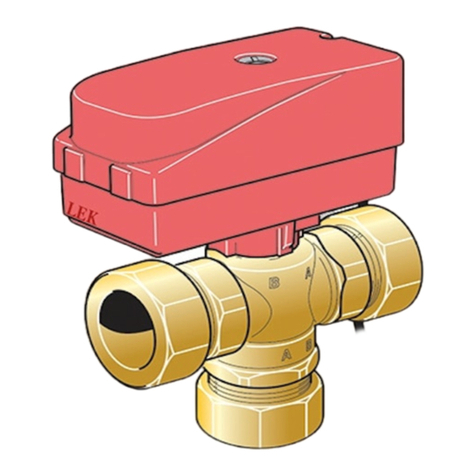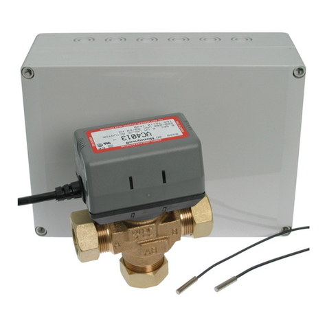
INSTALLING THE VALVE MOTOR
Example installation:
1. Ensure that the depression, in the shaft (1a) and the
shaft on the valve (1b), are at 12 o'clock with the
port up. In this example ▲ and ■ are open while ●
to begin with is closed.
2. Ensure that the knob on the motor is turned all the
way to the right.
3. Turn the knob to the left to close ■ and open ●.
180°
1. 2.
LEK
LEK
LEK
LEK
LEK
LEK
The symbols are marked on the terminals.
CHANGING THE DIRECTION OF ROTATION
NOTE
Electrical installation and service must be car-
ried out under the supervision of a qualified
electrician. Cut the current with the circuit
breaker before carrying out any servicing.
Electrical installation and wiring must be carried
out in accordance with the stipulations in force.
Change the direction of rotation on the valve motor as
necessary.
1. Slacken off the screws and cap on the valve motor.
180°
1. 2.
LEK
LEK
LEK
LEK
LEK
LEK
2. Pull out the pins, turn them 90 ° and put them back.
Electrical connection
NOTE
Electrical installation and service must be car-
ried out under the supervision of a qualified
electrician. Cut the current with the circuit
breaker before carrying out any servicing.
Electrical installation and wiring must be carried
out in accordance with the stipulations in force.
The valve motor is connected according to the following
diagram.
Brown
1 ~
L
Neutral
Control phase
MBlue
Black
QN10
For more information about electrical connections, see
relevant Installer manual/Assembly and maintenance
instructions for the system to which the reversing valve
is to be connected.
Technical
specifications
VST 20
230 V,~50 HzVoltage
40kWkWMax. charge power
DN32 (1 1/4”)Connection
16.0Kvs
089 388Part No.
VST 20 | GB6


