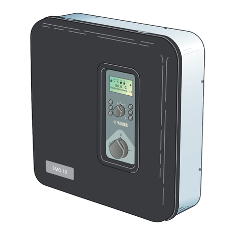
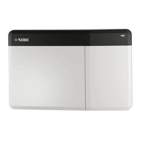
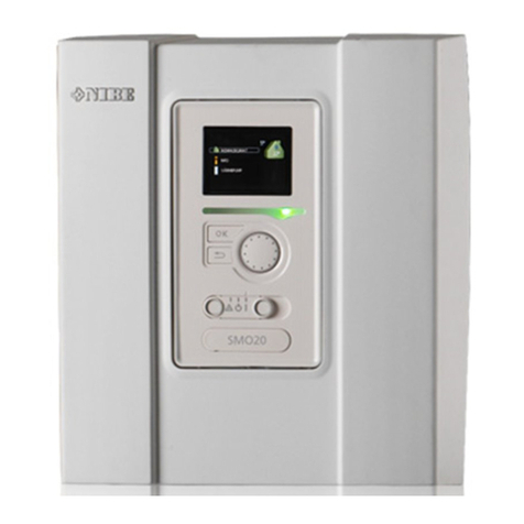
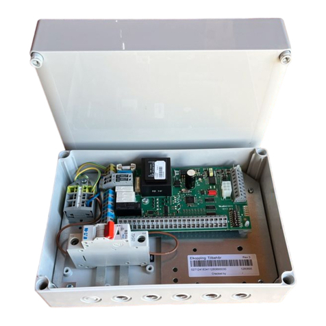
Nibe SMO 20 User manual

User manual
Control module
NIBE SMO 20
UHB EN 2235-1
731343

Quick guide
Navigation Ok button (confirm/select)
Back button (back/undo/exit)
Control knob (move/increase/reduce)
A detailed explanation of the button functions can be found on page 8.
How to scroll through menus and make different settings is described on page 12.
temperature 1.1
Set the indoor climate
2X
INDOOR CLIMATE
HOT WATER
INFO
HEAT PUMP
The mode for setting the indoor temperature is accessed by pressing the OK button twice, when in the start mode in
the main menu. Read more about the settings on page 16.
INDOOR CLIMATE
HOT WATER
INFO
HEAT PUMP
off
temporary lux 2.1
3 hrs
6 hrs
12 hrs
one time
increase
Increase hot water volume
2X
1X
To increase the amount of hot water temporarily (if a water heater is installed for your SMO 20), first turn the control
knob to select menu 2 (water droplet) and then press the OK button twice. Read more about the settings on page
temporary lux.
In event of disturbances in comfort
If you experience any disturbance in comfort, there are some measures you can take yourself before you need to contact
your installer. See section "Disturbances in comfort" for instructions.

41 Important information
4Installation data
5Safety information
7SMO 20 – An excellent choice
82 The control module – the heart of the house
8Control module's function
8Contact with SMO 20
15Maintenance of SMO 20
163 SMO 20 – at your service
16Set the indoor climate
25Set the hot water capacity
28Get information
31Adjust the heat pump
414 Disturbances in comfort
41Info-menu
41Manage alarm
43Add. heat only
445 Technical data
456 Glossary
47Item register
51Contact information
3Table of ContentsNIBE SMO 20
Table of Contents

Installation data
SMO 20Product
Serial number
Serial number, heat pump
Installation date
Installer
Type of docking
Accumulator/
water heater
Heat pump/
capacity
Add. heat type/power
SetDefault settingsNameNo.
0 / 9heating curve (offset/curve slope)1.9.1
Serial number must always be given.
Certification that the installation is carried out according to instructions in the accompanying installer manual and applicable regulations.
____________________________________________________________Signed_____________________________________Date
NIBE SMO 20Chapter 1 | Important information4
Important information

Safety information
This appliance can be used by children aged from 8 years and above and persons
with reduced physical, sensory or mental capabilities or lack of experience and
knowledge if they have been given supervision or instruction concerning use of
the appliance in a safe way and understand the hazards involved. Children shall
not play with the appliance. Cleaning and user maintenance shall not be made
by children without supervision.
This is an original manual. It may not be translated without the approval of NIBE.
Rights to make any design or technical modifications are reserved.
©NIBE 2022.
SMO 20 must be installed via an isolator switch. The cable area has to be dimen-
sioned based on the fuse rating used.
If the supply cable is damaged, only NIBE, its service representative or similar au-
thorised person may replace it to prevent any danger and damage.
5Chapter 1 | Important informationNIBE SMO 20

SYMBOLS
Explanation of symbols that may be present in this manual.
NOTE
This symbol indicates danger to person or machine.
Caution
This symbol indicates important information about what you should observe when maintaining your in-
stallation.
TIP
This symbol indicates tips on how to facilitate using the product.
SERIAL NUMBER
The serial number can be found on the top of the cover for the control module and in the info menu (menu 3.1).
LEK
Serial number
Caution
You need the product's (14 digit) serial number for servicing and support.
NIBE SMO 20Chapter 1 | Important information6

SMO 20 – An excellent choice
SMO 20 is a control module, which has been introduced to supply your home with environmentally friendly heating
in the most efficient way. Heat production is reliable and economical with a NIBE air/water heat pump and accu-
mulator/water heater.
Additional heat (for example electric/gas boiler) can engage automatically if something unexpected should occur
or as emergency operation.
EXCELLENT PROPERTIES FOR SMO 20:
•Easy to read display
The control module has an easy to read display with easy-to-understand menus that facilitate setting a com-
fortable indoor climate.
•Easy to install
SMO 20 is easy to install together with a compatible NIBE air/water heat pump. When installing, the control
module is connected to the heat pump, which enables you to see any heat pump alarms in SMO 20. The size of
the control module means that it can be installed on indoor walls for easy access to control your installation.
7Chapter 1 | Important informationNIBE SMO 20

Control module's function
SMO 20 is a simple control module, which, together with a NIBE air/water heat pump, accumulator/water heater
and additional heating (e.g. electric/gas boiler), creates a complete installation. Among other things, it controls
the heat pump, circulation pumps, reversing valves and additional heat to supply your home with environmentally
friendly heating in the most efficient way.
Contact with SMO 20
DISPLAY UNIT
A
B
C
D
E
F
Display
Status lamp
OK button
Back button
Control knob
Switch
INDOOR CLIMATE
HOT WATER
INFO
HEAT PUMP
SMO20 GUSB port
There is a display unit on the front of the control module, which is used to communicate with SMO 20. Here you:
•switch on, switch off or set the installation to emergency mode.
•set the indoor climate and hot water as well as adjust the installation to your needs.
•receive information about settings, status and events.
•see different types of alarms and receive instructions about how they are to be rectified.
Display
Instructions, settings and operational information are shown on the display. You can easily navigate between the
different menus and options to set the comfort or obtain the information you require.
A
Status lamp
The status lamp indicates the status of the control module. It:
•lights green during normal operation.
•lights yellow in emergency mode.
•lights red in the event of a deployed alarm.
B
OK button
The OK button is used to:
•confirm selections of sub menus/options/set values/page in the start guide.
C
Back button
The back button is used to:
•go back to the previous menu.
•change a setting that has not been confirmed.
D
Control knob
The control knob can be turned to the right or left. You can:
•scroll in menus and between options.
•increase and decrease the values.
•change page in multiple page instructions (for example help text and service info).
E
NIBE SMO 20Chapter 2 | The control module – the heart of the house8
The control module – the heart of the house

Switch
The switch assumes three positions:
•On ()
•Standby ( )
•Emergency mode ( )
The emergency mode must only be used in the event of a fault in the control module. In this mode, the compressor
in the heat pump switches off and any immersion heater engages. The control module display is not lit and the status
lamp shines yellow.
F
USB port
The USB port is hidden beneath the plastic badge with the product name on it.
The USB port is used to update the software.
Visit nibeuplink.com and click the "Software" tab to download the latest software for your installation.
G
9Chapter 2 | The control module – the heart of the houseNIBE SMO 20

MENU SYSTEM
INDOOR CLIMATE
HOT WATER
INFO
HEAT PUMP
Indoor temperature -
(if room sensors are
installed)
Hot water temp.
Temporary lux (if
activated)
Outdoor
temperature
Estimated amount of
hot water
MENU 1 - INDOOR CLIMATE
Setting and scheduling the indoor climate. See page 16.
MENU 2 - HOT WATER
Setting and scheduling hot water production. See page 25.
This menu only appears if a water heater is installed in the system.
MENU 3 - INFO
Display of temperature and other operating information and access to the alarm log. See page 28.
MENU 4 - MY SYSTEM
Setting time, date, language, display, operating mode etc. See page 31.
NIBE SMO 20Chapter 2 | The control module – the heart of the house10

Symbols in the display
The following symbols can appear in the display during operation.
DescriptionSymbol
This symbol appears by the information sign if there is information in menu 3.1 that you should note.
These two symbols indicate if the compressor in the outdoor module or the additional heat in the installation
is blocked via SMO 20.
These can, for example, be blocked depending on which operating mode is selected in menu 4.2, if blocking is
scheduled in menu 4.9.5 or if an alarm has occurred that blocks one of them.
Blocking the compressor.
Blocking additional heat.
This symbol appears if periodic increase or lux mode for the hot water is activated.
This symbol indicates whether "holiday setting" is active in 4.7.
This symbol indicates whether SMO 20 has contact with NIBE Uplink.
This symbol is visible in installations with active solar accessories.
This symbol indicates whether cooling is active.
Heat pump with cooling function required.
11Chapter 2 | The control module – the heart of the houseNIBE SMO 20

INDOOR CLIMATE
HOT WATER
INFO
HEAT PUMP
temperature
INDOOR CLIMATE 1
advanced
scheduling off
Marked main
menu
Menu number – marked sub menu
Name and menu number – main
menu
Symbol –
main menu
Status information – sub
menus
Name – sub menusSymbols – sub menus
Operation
To move the cursor, turn the control knob to the left or the right. The marked position is brighter and/or
has a light frame.
Selecting menu
To advance in the menu system select a main menu by marking it and then pressing the OK button.
A new window then opens with sub menus.
Select one of the sub menus by marking it and then pressing the OK button.
Selecting options
economy
comfort mode 2.2
normal
luxury
smart control
In an options menu the current selected option is indicated by a green tick.
To select another option:
1. Mark the applicable option. One of the options is pre-selected (white).
2. Press the OK button to confirm the selected option. The selected option has a green tick.
NIBE SMO 20Chapter 2 | The control module – the heart of the house12

Setting a value
time & date 4.4
time
day
year
month
24 h
12 h
date
Values to be changed
To set a value:
1. Mark the value you want to set using the control knob.
2. Press the OK button. The background of the value becomes green, which means that you have accessed
the setting mode.
3. Turn the control knob to the right to increase the value and to the left to reduce the value.
4. Press the OK button to confirm the value you have set. To change and return to the original value, press
the Back button.
Use the virtual keyboard
Different keyboards
In some menus where text may require entering, a virtual keyboard is available.
Depending on the menu, you can gain access to different character sets which you can select using the control
knob. To change character table, press the Back button. If a menu only has one character set the keyboard is
displayed directly.
When you have finished writing, mark "OK” and press the OK button.
13Chapter 2 | The control module – the heart of the houseNIBE SMO 20

Scroll through the windows
A menu can consist of several windows. Turn the control knob to scroll between the windows.
Current menu
window
Number of
windows in the
menu
Scroll through the windows in the start guide
language 4.6
If the start guide is left on this page it
closes automatically in
60 min
Arrows to scroll through window in start guide
1. Turn the control knob until one of the arrows in the top left corner (at the page number) has been marked.
2. Press the OK button to skip between the steps in the start guide.
Help menu
In many menus there is a symbol that indicates that extra help is available.
To access the help text:
1. Use the control knob to select the help symbol.
2. Press the OK button.
The help text often consists of several windows that you can scroll between using the control knob.
NIBE SMO 20Chapter 2 | The control module – the heart of the house14

Maintenance of SMO 20
REGULAR CHECKS
Your heat pump requires minimal maintenance after commissioning. On the other hand, it is recommended that
you check your installation regularly. For more information regarding the maintenance of heat pumps and/or ac-
cumulator tanks/water heaters, refer to the relevant manual.
If anything unusual occurs, messages about the malfunction appear in the display in the form of various alarm
texts. See alarm management on page 41.
SAVING TIPS
Your installation produces heat and hot water. This occurs via the control settings you made.
Factors that affect the energy consumption are, for example, indoor temperature, hot water consumption, the
insulation level of the house and whether the house has many large window surfaces. The position of the house,
e.g. wind exposure is also an affecting factor.
Also remember:
•Open the thermostat valves completely (except in rooms where you want it to be cooler). This is important, as
fully or partially closed thermostat valves slow the flow in the climate system, which results in the installation
working at a higher temperature. This in turn can lead to increased energy consumption.
•You can lower the operating cost when away from home by scheduling selected parts of the system. This is
done in menu 4.7 "holiday setting". See page 36 for instructions.
•If you activate "economy" in menu 2.2 "comfort mode", less energy is used.
Power consumption
Energiförbrukning fördelat över året
0%
5%
10%
15%
20%
25%
jan feb mars april maj juni juli aug sep okt nov dec
Månad
% av årsförbrukningen
Month
Jan Feb Mar April May June July Aug Sep Oct Nov Dec
% of annual
consumption
Increasing the indoor temperature by 1°C increases power consumption by approx. 5%.
Energy meter
Check the accommodation's energy meter regularly, preferably once a month. This will indicate any changes in
power consumption.
15Chapter 2 | The control module – the heart of the houseNIBE SMO 20

Set the indoor climate
OVERVIEW
Sub-menus
temperature
INDOOR CLIMATE 1
advanced
scheduling off
For the menu INDOOR CLIMATE there are several sub-menus. Status inform-
ation for the relevant menu can be found on the display to the right of the
menus.
temperature Setting the temperature for the climate system. The status
information shows the set values for the climate system.
scheduling Scheduling heating and cooling. Status information "set" is
displayed if you set a schedule but it is not active now, "holiday setting" is
displayed if the vacation schedule is active at the same time as the schedule
(the vacation function is prioritised), "active" displays if any part of the
schedule is active, otherwise it displays " off".
advanced Setting of heat curve, adjusting with external contact, minimum value for supply temperature, room
sensor and cooling function.
MENU 1.1 - TEMPERATURE
temperature 1.1.1
temperature cooling 1.1.2
Accessories are required to control the climate system using room sensors.
If you choose Menu 1.1 and do not have the cooling accessory, you come
directly to Menu 1.1.1.
Choose between heating or cooling and then set the desired temperature in
the next menu "temperature heating/cooling" in menu 1.1.
Set the temperature (with room sensor installed and
activated):
heating
Setting range: 5 – 30 °C
Default value: 20
cooling
Setting range: 5 – 30 °C
Default value: 25
The value in the display appears as a temperature in °C if the climate system
is controlled by a room sensor.
Caution
A slow heating system such as underfloor heating may not be suitable for control using the control
module’s room sensors.
To change the room temperature, use the control knob to set the desired temperature in the display. Confirm the
new setting by pressing the OK button. The new temperature is shown on the right-hand side of the symbol in
the display.
NIBE SMO 20Chapter 3 | SMO 20 – at your service16
SMO 20 – at your service

Setting the temperature (without room sensors activated):
Setting range: -10 to +10
Default value: 0
The display shows the set values for heating (curve offset). To raise or lower the indoor temperature, increase or
reduce the value on the display.
Use the control knob to set a new value. Confirm the new setting by pressing the OK button.
The number of steps the value has to be changed to achieve a degree change of the indoor temperature depends
on the heating installation. One step is usually enough but in some cases several steps may be required.
Setting the desired value. The new value is shown on the right-hand side of the symbol in the display.
Caution
An increase in the room temperature can be slowed by the thermostats for the radiators or under floor
heating. Therefore, open the thermostats fully, except in those rooms where a cooler temperature is re-
quired, e.g. bedrooms.
TIP
Wait 24 hours before making a new setting, so that the room temperature has time to stabilise.
If it is cold outdoors and the room temperature is too low, increase the curve slope in menu 1.9.1.1 by one
increment.
If it is cold outdoors and the room temperature is too high, reduce the curve slope in menu 1.9.1.1 by one
increment.
If it is warm outdoors and the room temperature is too low, increase the value in menu 1.1.1 by one incre-
ment.
If it is warm outdoors and the room temperature is too high, reduce the value in menu 1.1.1 by one incre-
ment.
MENU 1.3 - SCHEDULING
scheduling 1.3
cooling off
heating off
In the menu scheduling indoor climate (heating/cooling) is scheduled for
each weekday.
You can also schedule a longer time during a selected period (holiday) in
menu 4.7.
MENU 1.3.1 - HEATING
Increases or decreases in the accommodation temperature can be scheduled here for up to three time periods
per day. One step is usually enough to change the room temperature by one degree, but in some cases several
steps may be required.
If a room sensor is installed and activated, the desired room temperature (°C) is set during the time periods.
17Chapter 3 | SMO 20 – at your serviceNIBE SMO 20

SCHEDULING HEATING 1.3.1
activated
schedule 2 schedule 3schedule 1
all
mon
tues
wed
thur
fri
sat
sun
21:30 -
06:00 20.5°
Time period AdjustingDay
Activated Schedule
Conflict
Schedule: The schedule to be changed is selected here.
Activated: Scheduling for the selected period is activated here. Set times are not affected at deactivation.
Day: Select which day or days of the week the scheduling is to apply to here. To remove the scheduling for a par-
ticular day, the time for that day must be reset by setting the start time to the same as the stop time. If the row
"all" is used, all days in the period are set according to that row.
Time period: The start and stop time for the selected day for scheduling are selected here.
Adjustment: How much the heating curve is to be offset in relation to menu 1.1 during scheduling is set here. If a
room sensor is installed, the desired room temperature is set in °C.
Conflict: If two settings conflict with each other, a red exclamation mark is displayed.
TIP
If you wish to set similar scheduling for every day of the week start by filling in “all” and then changing
the desired days.
TIP
Set the stop time earlier than the start time so that the period extends beyond midnight. Scheduling
then stops at the set stop time the day after.
Scheduling always starts on the date that the start time is set for.
Caution
Changes of temperature in accommodation take time. For example, short time periods in combination
with underfloor heating will not give a noticeable difference in room temperature.
MENU 1.3.2 - COOLING
Here you can schedule when cooling is permitted in the accommodation for up to two different time periods per
day.
NIBE SMO 20Chapter 3 | SMO 20 – at your service18

SCHEDULING COOLING 1.3.2
activated
schedule 2schedule 1
all
mon
tues
wed
thur
fri
sat
sun
21:30 -
06:00 on
Activated Schedule
Time period AdjustingDay Conflict
Schedule: The schedule to be changed is selected here.
Activated: Scheduling for the selected period is activated here. Set times are not affected at deactivation.
Day: Select which day or days of the week the scheduling is to apply to here. To remove the scheduling for a par-
ticular day, the time for that day must be reset by setting the start time to the same as the stop time. If the row
"all" is used, all days in the period are set according to that row.
Time period: The start and stop time for the selected day for scheduling are selected here.
Adjustment: Here, you schedule when cooling will not be permitted.
Conflict: If two settings conflict with each other, a red exclamation mark is displayed.
TIP
If you wish to set similar scheduling for every day of the week start by filling in “all” and then changing
the desired days.
TIP
Set the stop time earlier than the start time so that the period extends beyond midnight. Scheduling
then stops at the set stop time the day after.
Scheduling always starts on the date that the start time is set for.
MENU 1.9 - ADVANCED
advanced 1.9
curve
external adjustment
min. flow line temp.
room sensor settings
cooling settings
own curve
Menu advanced is intended for the advanced user. This menu has several
sub-menus.
curve Setting the curve slope for heating and cooling.
external adjustment Setting the heat curve offset when the external contact
is connected.
min. flow line temp. Setting minimum permitted flow line temperature.
room sensor settings Settings regarding the room sensor.
cooling settings Settings for cooling.
own curve Setting own curve for heating and cooling.
point offset Setting the offset of the heating curve or cooling curve at a specific outdoor temperature.
19Chapter 3 | SMO 20 – at your serviceNIBE SMO 20

MENU 1.9.1 - CURVE
heating curve
heating curve 1.9.1.1
system
outdoor temp. °C
flow temperature °C
Setting range: 0 – 15
Default value: 9
cooling curve
cooling curve 1.9.1.2
system
outdoor temp. °C
flow temperature °C
Setting range: 0 – 9
Default value: 0
The prescribed heating curve for your house can be viewed in the menu heating curve . The task of the heating
curve is to give an even indoor temperature, regardless of the outdoor temperature, and thereby energy efficient
operation. It is from this heating curve that the control module's control computer determines the temperature
of the water to the heating system, supply temperature, and therefore the indoor temperature. Select the heating
curve and read off how the supply temperature changes at different outdoor temperatures here. If there is access
to cooling the same settings can be made for the cooling curve.
Caution
With underfloor heating systems, max flow line temperature should normally be set to between 35 and
45 °C.
With underfloor cooling, "min. flow line temp." must be restricted to prevent condensation.
Check the max temperature for your floor with your installer/floor supplier.
TIP
Wait 24 hours before making a new setting, so that the room temperature has time to stabilise.
If it is cold outdoors and the room temperature is too low, increase the curve slope by one increment.
If it is cold outdoors and the room temperature is too high, lower the curve slope by one increment.
If it is warm outdoors and the room temperature is too low, increase the curve offset by one increment.
If it is warm outdoors and the room temperature is too high, lower the curve offset by one increment.
Cooling in 2-pipe system
SMO 20 contains a built-in function for operating cooling in a 2-pipe system down to 7 °C, factory setting 18 °C.
This requires that the outdoor module can perform cooling. (See the Installer Manual for your air/water heat pump.)
If the outdoor module is permitted to run cooling, the cooling menus are activated in the display on SMO 20.
In order for operating mode “cooling” to be permitted, the average temperature must be above the setting value
for “start cooling” in menu 4.9.2
The cooling settings for the climate system are adjusted in the indoor climate menu, menu 1.
NIBE SMO 20Chapter 3 | SMO 20 – at your service20
Other manuals for SMO 20
9
Table of contents
Other Nibe Controllers manuals
Popular Controllers manuals by other brands

RESEARCH CONCEPTS
RESEARCH CONCEPTS RC2000C manual

Lennox
Lennox M0STAT120N-1 Installation and user information

SSD Drives
SSD Drives 650V product manual

Wibre
Wibre 4.1913 Series installation manual

VS LIGHTING SOLUTIONS
VS LIGHTING SOLUTIONS iMCU Mounting instruction

CircuitWerkes
CircuitWerkes Sicon-8 Operation & technical manual

Castle Creations
Castle Creations HYDRA XLX2 quick start guide

Tech Controllers
Tech Controllers EU-19 user manual

Twitoplast
Twitoplast C210 Installation & operation instructions

Zaiput Flow Technologies
Zaiput Flow Technologies BPR-1000 instruction manual

YOKOGAWA
YOKOGAWA UT75A user manual

Prolon
Prolon PL-C1000 Series Operational guide