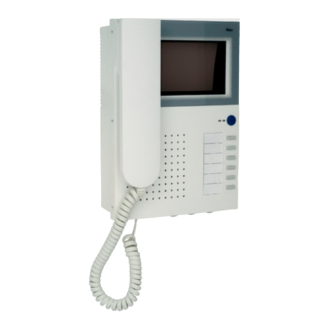
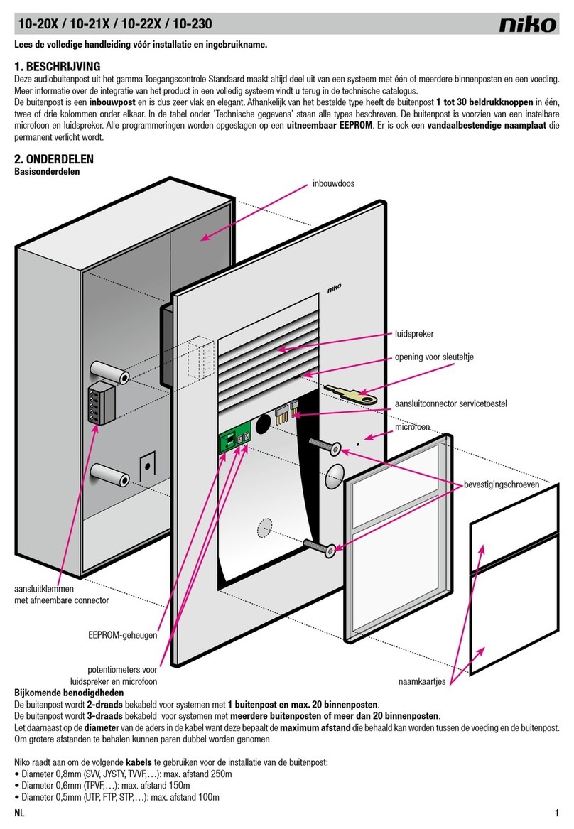
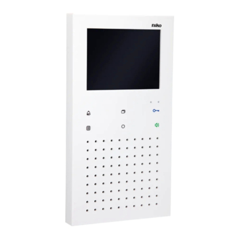
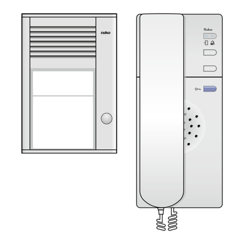
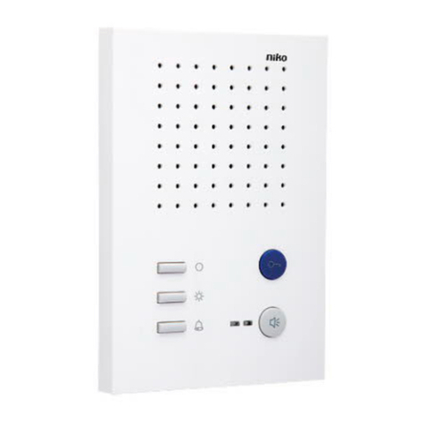
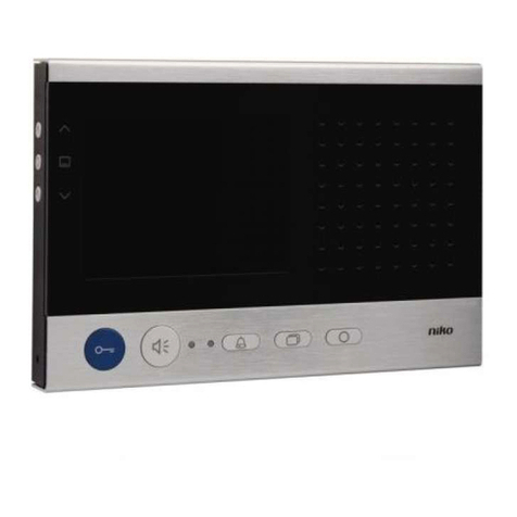
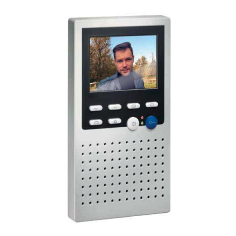
Niko 10-525 User manual

10-525

10-525
7
5
3
9
8
4
2
1
6

10-525
34
Fig./Abb./Obr. 6
a b
1
2

10-525
1
Lees de volledige handleiding vóór installatie en ingebruikname. Bewaar deze handleiding zorgvuldig voor later gebruik.
1. BESCHRIJVING
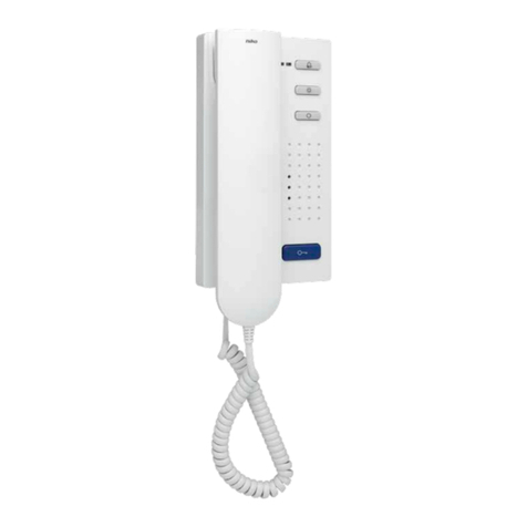
Deze compacte audiobinnenpost uit het Niko toegangscontrolegamma is geschikt voor opbouw en maakt altijd deel uit van een installatie met
één of meerdere buitenposten en een voeding.
Met het toestel kun je:
• een deur openen
• een gesprek voeren
• het belsignaal in- en uitschakelen
• het licht of een extra contact schakelen.
2. ONDERDELEN
toets om het belsignaal in en uit te schakelen
groene en rode indicatieleds voor bezet- en oproepsignaal
toets om het licht te schakelen
vrije functietoets
luidspreker voor het belsignaal
deuropenertoets
volumeregelaar om het bel- en spraakvolume in te stellen
spraaktoets
microfoon
3. INSTALLATIE
3.1. Bekabeling
Welk type kabel gebruik ik?
De diameter van de aders bepaalt de maximale afstand van de voeding tot de binnen- of buitenpost. Je verdubbelt de maximale afstand door twee
paren samen te nemen.
De onderstaande tabel geeft een overzicht van de maximale afstand per type kabel.
Kabeldiameter Maximale afstand
0,5 mm (bv. UTP, cat. 5E) 100 m
0,6 mm (bv. TPVF) 150 m
0,8 mm (bv. SVV, TVVF, JYSTY, …) 250 m
Gebruik ik een tweedraads- of driedraadsbekabeling?
Voor kleine installaties met één buitenpost gebruik je een tweedraadsbekabeling. Er kunnen maximaal twee binnenposten terzelfder tijd worden
opgeroepen.
In alle andere gevallen met meer dan één buitenpost hanteer je een driedraadsbekabeling, waarbij maximaal vier binnenposten (in combinatie
met de voeding 10-801) of meer (in combinatie met andere voedingen) terzelfdertijd kunnen worden opgeroepen.
Voeding Maximaal aantal 10-525 Bekabeling
10-801 20 tweedraads
10-802 80 tweedraads
10-806 30 tweedraads
10-801 20 driedraads
10-802 80 driedraads
10-806 90 driedraads
10-801 + 10-805-01 90 driedraads
10-802 + 10-805-01 270 driedraads
1
2
3
4
5
6
7
8
9

10-525
2
3.2. Aansluiting en (de)montage
Stap Actie Tip
1. Aansluiting Sluit de binnenpost aan volgens het aansluitschema
(fig. 1).
Installeer de binnenpost niet onder spanning. Sluit
het toestel pas na volledige installatie aan op de
netspanning.
2. Montage van het onderkader Schroef het onderkader met drie schroeven vast
(fig. 2).
Om de aansluitkabel probleemloos te kunnen binnen-
brengen, wordt het aanbevolen onder het toestel een
inbouwdoos te monteren.
Plaats de inbouwdoos onder de kabelingang op een
hoogte van 150 cm.
3. Tweedraads- of
driedraadsbekabeling
tweedraads:
- Gebruik de klemmen a en b.
driedraads:
- Gebruik de klemmen a, b en P (voor extra voeding).
- Verander de positie van de steekbrug aan de
binnenzijde van het bovenkader (fig. 3).
Beperk de lengte van de draden boven het onderka-
der om te vermijden dat deze gekneld raken bij het
opklikken van het bovenkader.
4. Optioneel: Aansluiting van
een beldrukknop (05-540)
Sluit de beldrukknop aan op de klemmen a en E
(fig. 4).
* Verwijder het lampje uit de beldrukknop om te
vermijden dat het continu stroom verbruikt en er niet
meer kan worden gebeld.
5. Montage van het bovenkader
(fig. 5)
a. Plaats het bovenkader op de twee
vergrendelingshaken van het onderkader.
b.Klik het bovenkader met lichte druk vast op het
onderkader.
6. Demontage (fig. 6) a. Plaats met lichte druk een kleine schroevendraaier
in de rechthoekige ontgrendelingsopening
onderaan op het toestel.
b.Maak het bovenkader los aan de onderzijde (1).Til
het bovenkader uit de twee vergrendelingshaken
van het onderkader (2).
4. WERKING EN GEBRUIK
4.1. Functietoetsen
Toets Functie
Met deze toets kun je:
• de deur openen;
• de lichtschakelfunctie in werking laten treden (als deze functie op de buitenpost geactiveerd is zie handleiding van
voeding 10-801);
• een beltoon voor een deuroproep selecteren (zie § 5.2.).
Je schakelt het belsignaal uit als je kort op deze toets drukt. De rode indicatieled brandt.
Je schakelt het belsignaal opnieuw in als je nogmaals op deze toets drukt. De rode indicatieled gaat uit.
Je activeert de beltoonselectie als je deze toets acht seconden ingedrukt houdt (zie § 5.2.).
Met deze toets kun je:
• het licht in- en uitschakelen;
• een beltoon voor een etageoproep selecteren (zie § 5.2.).
Aan deze vrije functietoets kun je een van de volgende functies toewijzen:
• stuurfunctie 8 om de DIN-railrelais (10-831) te bedienen (standaard);
• interne oproep;
• bel-en-kom-binnenfunctie;
• oproepdoorschakeling.
Je gebruikt deze toets eveneens om de toegewezen functie te activeren of te deactiveren na programmatie met het
servicetoestel
Met deze toets kun je ook een beltoon voor een interne oproep selecteren (zie § 5.2.).
Met de spraaktoets kun je:
• een oproep aanvaarden en met de bezoeker communiceren;
• een oproep beëindigen.

10-525
3
4.2. Indicatieleds
Status Betekenis
De rode indicatieled brandt als het belsignaal uitgeschakeld is.
De rode indicatieled knippert in de volgende gevallen:
• De oproepdoorschakeling is geactiveerd.
• De bel-en-kom-binnenfunctie is geactiveerd.
• Het belsignaal is gedeactiveerd.
De rode indicatieled gaat uit in de volgende gevallen:
• Het belsignaal is geactiveerd.
• De oproepdoorschakeling is gedeactiveerd.
• De bel-en-kom-binnenfunctie is gedeactiveerd.
De groene indicatieled brandt in de volgende gevallen:
• oproep aan de buitenpost;
• tijdens een gesprek.
De groene indicatieled knippert driemaal als de lijn bezet is (iemand anders is in gesprek).
Beide indicatieleds branden als de beltoonselectie geactiveerd is (zie § 5.2.).
Beide indicatieleds knipperen bij een foutmelding (zie § 6).
4.3. Volumeregelaar
Met het wieltje onderaan op de binnenpost kies je uit acht niveaus om – onafhankelijk van elkaar – het bel- en spraakvolume in te stellen:
• Tijdens een gesprek stel je het spraakvolume instelbaar.
• Als er geen gesprek is, stel je het beltoonvolume in.
5. INSTELLINGEN EN PROGRAMMERING
5.1. Programmering met het servicetoestel
Om de binnenpost aan een beldrukknop toe te wijzen als eerste of tweede toestel, raadpleeg je de handleiding van de voeding (10-80X) of het
servicetoestel (10-870).
Om de binnenpost aan een beldrukknop toe te wijzen als derde of vierde toestel, schakel je het toestel parallel (als slave) met een andere
binnenpost.
Tip: Voor een vlotte programmering kleef je de serienummers van alle binnen- en buitenposten die deel uitmaken van de installatie, op het
aansluitschema. Je vindt de serienummers terug op zowel de verpakking als het toestel. Het serienummer van deze binnenpost vind je terug aan
de binnenzijde van het bovenkader.
1. Sluit het servicetoestel aan op de installatie via de klemmen a, b en P of via de daartoe bestemde connector op de buitenpost.
2. Geef de toetsencombinatie in op het servicetoestel afhankelijk van de actie die je wilt uitvoeren.

10-525
4
Actie Toetsencombinatie
Binnenpost zoeken * 52 #
Oproepdoorschakeling programmeren * 90 # serienummer binnenpost # serienummer binnenpost voor
doorschakeling #
Je activeert deze functie met de vrije functietoets (zie § 4.1)
Bel-en-kom-binnenfunctie programmeren * 91 # serienummer binnenpost #
Je activeert deze functie met de vrije functietoets (zie § 4.1)
Interne oproep programmeren * 92 # serienummer binnenpost # serienummer op te roepen
binnenpost #
Je activeert deze functie met de vrije functietoets (zie § 4.1)
Stuurfunctie 8 voor de DIN-railrelais programmeren * 93 # serienummer binnenpost #
Je activeert deze functie met de vrije functietoets (zie § 4.1)
Binnenpost als slave aansluiten op een master (parallelschakeling) * 99 # serienummer binnenpost # serienummer master #
Programmering van master en slave uitschakelen * 99 # serienummer binnenpost # 0 #
Opgelet: Je kunt slechts een van de vier functies (90, 91, 92, 93) per binnenpost programmeren.
5.2. Beltoon instellen
De binnenpost kan een onderscheid maken tussen een oproep aan twee verschillende buitenposten (deuroproep), een etageoproep en een
oproep aan een andere binnenpost (interne oproep). Voor elk type oproep is er een aparte beltoon voorzien die je kunt instellen. Je hebt de
keuze uit 13 beltonen.
Stap Actie Resultaat
1. Druk gedurende acht seconden op .Je hoort een pieptoon en beide indicatieleds branden. De
beltoonselectie is geactiveerd.
2. Druk meermaals op een van de volgende functietoetsen:
• deuroproep:
• etageoproep:
• interne oproep:
Je doorloopt de verschillende beltonen per type oproep. De laatst
geselecteerde beltoon wordt bewaard in het toestelgeheugen.
3. Druk kort op of wacht acht seconden. Je hoort een pieptoon en beide indicatieleds gaan uit. De
beltoonselectie is gedeactiveerd.
5.3. Tijdsinstellingen
De tijdsinstellingen op de binnenpost zijn bij levering als volgt:
Parameter Fabrieksinstelling
Spreektijd na het starten van een gesprek 2 min (*)
Aantal keer dat de groene indicatieled knippert als de lijn bezet is driemaal binnen 2 s
Duur dat de oproep aan een buitenpost of een etageoproep gesignaleerd blijft 30 s
Duur dat een door jezelf gemaakte interne oproep gesignaleerd blijft 30 s
* Je kan de spreektijd instellen met het servicetoestel (10-870). Raadpleeg de handleiding van dit toestel voor meer informatie.
6. PROBLEEMOPLOSSING
1. Controleer altijd eerst met een multimeter de spanning tussen de klemmen:
Tussen de klemmen … Moet de volgende spanning aanwezig zijn
b en a + 24 Vdc ± 8%
b en P + 24 Vdc ± 8%

10-525
5
2. Is het toestelprobleem niet verholpen, doorloop dan onderstaande lijst van mogelijke problemen:
Probleem Oorzaak Oplossing
Je hoort een negatieve toon (hoog – laag) als
je op een beldrukknop drukt.1
Er zit een fout in de programmering. Wis de programmering en herbegin.
De installatie bevindt zich nog in
programmeermode.
Verlaat de programmeermode.
De binnenpost is niet correct aangesloten. Controleer de bedrading volgens het
aansluitschema.
Er is een oproep, maar je hoort geen
belsignaal en de rode indicatieled brandt.
Het belsignaal is uitgeschakeld. Druk op om het belsignaal opnieuw in
te schakelen. De rode indicatieled brandt
niet meer.
Je hoort een fluittoon tijdens een gesprek. De buitenpost is niet goed afgesteld. Wijzig de geluidssterkte van de microfoon en
de luidspreker via de potentiometers op de
buitenpost tot de fluittoon verdwijnt.
Beide indicatieleds knipperen continu.1De a- en P-ader zijn verwisseld of kortge-
sloten.
Je hoort de volgende fouttoon:
Wissel de a- en P-ader om of los de
kortsluiting op.
Het toestel keert terug in rustmode.
De a-ader is niet aangesloten of krijgt geen
stroom.
Je hoort de volgende fouttoon:
Sluit de a-ader aan en controleer de voeding.
Het toestel keert terug in rustmode.
Er is een toets geblokkeerd (langer dan 15
seconden ingedrukt).
Je hoort de volgende fouttoon:
Maak de toets op het toestel of de
etagebeldrukknop los.
Het toestel keert terug in rustmode.
1 Neem contact op met een erkend installateur om het probleem te verhelpen.
7. ONDERHOUD
Vuil kan de werking van de binnenpost beïnvloeden. Houd daarom het toestel altijd schoon en droog. Gebruik een vochtige doek en water met
zeep om het toestel te reinigen.
Om te vermijden dat het oppervlak van het toestel beschadigd wordt, mogen geen schurende sponzen of reinigingsmiddelen, reinigingsmiddelen
op basis van een oplosmiddel, een zuur of azijnzuur of een hogedrukreiniger worden gebruikt.
Als er onderdelen van de binnenpost defect zijn, neem je contact op met een erkend installateur.
8. TECHNISCHE GEGEVENS
afmetingen 180 x 100 x 23 mm (HxBxD)
gewicht 185 g
materiaal van de behuizing PC+ABS
kleur van de behuizing wit
voedingsspanning + 24 Vdc ± 8%
maximale ingangsstroom I(Pmax) = 75 mA
ingangsstroom in rustmode - tweedraads: I(a) = 1 mA
- driedraads: I(a) = 0,2 mA – I(P) = 0,8 mA
beschermingsgraad IP30
omgevingstemperatuur -5 – +40°C
10-525
6
9. WAARSCHUWINGEN VOOR INSTALLATIE
• De installatie moet worden uitgevoerd door een erkend installateur en volgens de geldende voorschriften.
• Deze handleiding moet aan de gebruiker worden overhandigd. Het moet bij het dossier van de elektrische installatie worden gevoegd en worden
overgedragen aan eventuele nieuwe eigenaars. Bijkomende exemplaren zijn verkrijgbaar via de website of supportdienst van Niko. Op de Niko
website is altijd de meest recente handleiding van het product terug te vinden.
• Tijdens de installatie moet rekening gehouden worden met (niet-limitatieve lijst):
- de geldende wetten, normen en reglementen.
- de stand van de techniek op het moment van de installatie.
- deze handleiding die alleen algemene bepalingen vermeldt en moet worden gelezen in het kader van elke specifieke installatie.
- de regels van goed vakmanschap.
Dit product voldoet aan alle toepasselijke Europese richtlijnen en verordeningen. Indien van toepassing,vind je de EG-verklaring van overeenstemming
met betrekking tot dit product op www.niko.eu.
10. NIKO SUPPORT
Heb je twijfel? Of wil je het product omruilen in geval van een eventueel defect? Neem dan contact op met je groothandel of de Niko supportdienst:
• België: +32 3 778 90 80
• Nederland: +31 183 64 06 60
Contactgegevens en meer informatie vind je op www.niko.eu onder de rubriek “Hulp en advies”.
11. GARANTIEBEPALINGEN
•
De garantietermijn bedraagt vier jaar vanaf leveringsdatum. Als leveringsdatum geldt de factuurdatum van aankoop van het product door de
consument. Als er geen factuur voorhanden is, geldt de productiedatum.
•
De consument is verplicht Niko schriftelijk te informeren over het gebrek aan overeenstemming, en dit uiterlijk binnen de twee maanden na vaststelling.
• In geval van een gebrek aan overeenstemming heeft de consument enkel recht op een kosteloze herstelling of vervanging van het product, wat
door Niko bepaald wordt.
• Niko is niet verantwoordelijk voor een defect of schade als gevolg van een foutieve installatie, oneigenlijk of onachtzaam gebruik, een verkeerde
bediening, transformatie van het product, onderhoud in strijd met de onderhoudsvoorschriften of een externe oorzaak zoals vochtschade of schade
door overspanning.
• De dwingende bepalingen in de nationale wetgeving over de verkoop van consumptiegoederen en de bescherming van consumenten in landen
waar Niko rechtstreeks of via zuster- of dochtervennootschappen, filialen, distributeurs, agenten of vaste vertegenwoordigers verkoopt, hebben
voorrang op bovenstaande bepalingen.
Dit product mag u niet bij het ongesorteerd afval gooien. Breng uw afgedankt product naar een containerpark of een erkend verzamelpunt. Net als producenten en
importeurs speelt ook u een belangrijke rol in de bevordering van sortering, recycling en hergebruik van afgedankte elektrische en elektronische apparatuur. Om
de ophaling en verwerking te kunnen financieren, heft de overheid in bepaalde gevallen een recyclingbijdrage (inbegrepen in de aankoopprijs van dit product).
-

10-525
7
1
2
3
4
5
6
7
8
9
Veuillez lire le mode d’emploi entièrement avant l’installation et la mise en service. Veuillez conserver ce mode d’emploi afin de
pouvoir le consulter ultérieurement.
1. DESCRIPTION
Ce poste intérieur audio de la gamme de contrôle d’accès Niko convient pour un montage en saillie et fait toujours partie d’une installation
comportant un ou plusieurs postes extérieurs et une alimentation.
Cet appareil vous permet :
• d’ouvrir une porte;
• de mener une conversation;
• d’activer et désactiver le signal de sonnerie;
• de commuter l’éclairage ou un contact supplémentaire.
2. COMPOSANTS
1. touche d’activation et de désactivation du signal de sonnerie
2. LED d’indication verte et rouge pour un signal occupé et un signal d’appel
3. touche de commutation de l’éclairage
4. touche de fonction libre
5. haut-parleur du signal de sonnerie
6. touche de commande de gâche électrique
7. contrôle de volume pour le réglage du volume de sonnerie et de la parole
8. touche parole
9. microphone
3. INSTALLATION
3.1. Câblage
Quel type de câble dois-je utiliser ?
Le diamètre des conducteurs détermine la distance maximale entre l’alimentation et le poste intérieur ou extérieur. Vous doublez la distance
maximale en regroupant deux paires.
Le tableau ci-dessous donne un aperçu de la distance maximale par type de câble.
Diamètre du câble Distance maximale
0,5 mm (p.ex. UTP, cat. 5U) 100 m
0,6 mm (p.ex. TPVF) 150 m
0,8 mm (p.ex. SVV, TVVF, JYSTY …) 250 m
Dois-je utiliser un câblage à deux ou à trois fils ?
Pour les petites installations comportant un seul poste extérieur, vous utilisez un câblage à deux fils. Jusqu’à deux postes intérieurs peuvent être
appelés en même temps.
Dans tous les autres cas où l’installation comporte plus d’un poste extérieur, vous utilisez un câblage à trois fils. Au maximum quatre postes
intérieurs (en combinaison avec l’alimentation 10-801) ou plus (en combinaison avec d’autres alimentations) peuvent alors être appelés en même
temps.
Alimentation Nombre maximum de 10-525 Câblage
10-801 20 à deux fils
10-802 80 à deux fils
10-806 30 à deux fils
10-801 20 à trois fils
10-802 80 à trois fils
10-806 90 à trois fils
10-801 + 10-805-01 90 à trois fils
10-802 + 10-805-01 270 à trois fils

10-525
8
10-525
3.2. Raccordement et (dé)montage
Étape Action Conseil
1. Raccordement Raccordez le poste intérieur selon le schéma de
raccordement (fig. 1).
N’installez pas le poste intérieur sous tension. Ne
raccordez l’appareil à la tension réseau qu’après
installation complète.
2. Montage du cadre inférieur Fixez le cadre inférieur à l’aide de trois vis (fig. 2). Afin de pouvoir introduire facilement le câble de
raccordement, il est recommandé de monter une
boîte d’encastrement sous l’appareil.
3. Câblage à deux ou à trois fils à deux fils :
- Utilisez les bornes a et b.
à trois fils :
- Utilisez les bornes a, b et P (pour une alimentation
supplémentaire).
- Changez la position du pont enfichable à l’intérieur
du cadre supérieur (fig. 3).
Limitez la longueur des fils au-dessus du cadre
inférieur afin d’éviter qu’ils soient écrasés lorsque
vous encliquetez le cadre supérieur.
4. En option : raccordement
d’un bouton-poussoir de
sonnerie (05-540)
Raccordez le bouton-poussoir de sonnerie aux bornes
a et E (fig. 4).
Retirez la lampe du bouton-poussoir de sonnerie afin
d’éviter que la lampe consomme du courant de mani-
ère continue et qu’il ne soit plus possible de sonner.
5. Montage du cadre supérieur
(fig. 5)
a. Placez le cadre supérieur sur les deux crochets de
verrouillage du cadre inférieur.
b.Encliquetez le cadre supérieur sur le cadre
inférieur, en exerçant une légère pression.
6. Démontage (fig. 6) a. Insérez un petit tournevis dans l’ouverture de
déverrouillage rectangulaire qui se trouve au bas
de l’appareil, en exerçant une légère pression.
b.Détachez le cadre supérieur sur le dessous (1).
Soulevez le cadre supérieur afin de le retirer des
deux crochets de verrouillage du cadre inférieur (2).
4. FONCTIONNEMENT ET UTILISATION
4.1. Touches de fonction
Touche Fonction
Cette touche vous permet :
• d’ouvrir la porte;
• d’activer la fonction de commutation de l’éclairage (si cette fonction est activée sur le poste extérieur) (voir le manuel
de l’alimentation);
• de sélectionner une tonalité de sonnerie pour un appel de porte (voir § 5.2.).
Appuyez brièvement sur cette touche pour désactiver le signal de sonnerie. La LED d’indication rouge s’allume.
Pour réactiver le signal de sonnerie, vous appuyez de nouveau sur cette touche. La LED d’indication rouge s’éteint.
Vous activez la sélection de la tonalité de sonnerie en gardant cette touche enfoncée pendant huit secondes (voir
§ 5.2.).
Cette touche vous permet :
• d’allumer et d’éteindre la lumière;
• de sélectionner une tonalité de sonnerie pour un appel d’étage (voir § 5.2.).
Vous pouvez attribuer une des fonctionnalités suivantes à cette touche de fonction libre :
• fonction de commande 8 pour le relais sur rail DIN (10-831) (par défaut);
• appel interne;
• fonction ‘sonner et entrer’;
• transfert d’appels.
Vous utilisez également cette touche pour activer ou désactiver la fonction assignée après programmation à l’aide de
l’appareil de service.
Cette touche vous permet aussi de sélectionner une tonalité de sonnerie pour un appel interne (voir § 5.2.).
La touche parole vous permet :
• d’accepter un appel et de communiquer avec le visiteur;
• de mettre fin à un appel.

10-525
9
4.2. LED d’indication
Statut Signification
La LED d’indication rouge est allumée si le signal de sonnerie est désactivé.
La LED d’indication rouge clignote dans les cas suivants :
• Le transfert d’appels est activé.
• La fonction ‘sonner et entrer’ est activée.
• Le signal de sonnerie est désactivé.
La LED d’indication rouge s’éteint dans les cas suivants :
• Le signal de sonnerie est activé.
• Le transfert d’appels est désactivé.
• La fonction ‘sonner et entrer’ est désactivée.
La LED d’indication verte est allumée dans les cas suivants :
• appel au poste extérieur;
• pendant une conversation.
La LED d’indication verte clignote trois fois lorsque la ligne est occupée (quelqu’un d’autre est en ligne).
Les deux LED d’indication s’allument lorsque la sélection de la tonalité de sonnerie est activée (voir § 5.2.).
Les deux LED d’indication clignotent en cas d’un message d’erreur (voir chapitre 6).
4.3. Contrôle de volume
La molette au bas du poste intérieur vous choisissez parmi huit niveaux de réglage du volume de sonnerie et de la parole (indépendamment l’une
de l’autre) :
• Pendant une conversation, vous réglez le volume de la parole.
• S’il n’y a pas de conversation, vous réglez le volume de la tonalité de sonnerie.
5. RÉGLAGES ET PROGRAMMATION
5.1. Programmation à l’aide de l’appareil de service
Pour attribuer le poste intérieur à un bouton-poussoir de sonnerie en tant que premier ou deuxième appareil, vous consultez le manuel de
l’alimentation (10-80X) ou de l’appareil de service (10-870).
Pour attribuer le poste intérieur à un bouton-poussoir de sonnerie en tant que troisième ou quatrième appareil, vous commutez l’appareil en
parallèle (comme esclave) avec un autre poste intérieur.
Conseil : Pour faciliter la programmation, vous collez sur le schéma de raccordement les numéros de série de tous les postes intérieurs et
extérieurs faisant partie de l’installation. Vous trouverez ces numéros sur l’appareil et sur son emballage. Le numéro de série de ce poste intérieur
est indiqué à l’intérieur du cadre supérieur.
1. Connectez l’appareil de service à l’installation au moyen des bornes a, b et P ou du connecteur prévu à cet effet sur le poste extérieur.
2. Saisissez la combinaison de touches sur l’appareil de service, selon l’action que vous souhaitez exécuter.

10-525
10
Action Combinaison de touches
Recherche du poste intérieur * 52 #
Programmation du transfert d’appels * 90 # numéro de série du poste intérieur # numéro de série du poste
intérieur vers lequel les appels sont déviés #
Vous activez cette fonction à l’aide de la touche de fonction libre (voir
§4.1)
Programmation de la fonction ‘sonner et entrer’ * 91 # numéro de série du poste intérieur #
Vous activez cette fonction à l’aide de la touche de fonction libre (voir
§4.1)
Programmation de l’appel interne * 92 # numéro de série du poste intérieur # numéro de série du poste
intérieur à appeler #
Vous activez cette fonction à l’aide de la touche de fonction libre (voir
§4.1)
Programmation de la fonction de commande 8 pour le relais sur rail
DIN
* 93 # numéro de série du poste intérieur #
Vous activez cette fonction à l’aide de la touche de fonction libre (voir
§4.1)
Raccordement du poste intérieur comme esclave sur un maître
(commutation en parallèle)
* 99 # numéro de série du poste intérieur # numéro de série du
maître #
Désactivation de la programmation du maître et de l’esclave * 99 # numéro de série du poste intérieur # 0 #
Attention: Vous ne pouvez programmer qu’une seule des quatre fonctions (90, 91, 92, 93) par poste intérieur.
5.2. Réglage de la tonalité de sonnerie
Le poste intérieur peut faire une distinction entre un appel depuis deux postes extérieurs différents (appel de porte), un appel d’étage et un
appel depuis un autre poste intérieur (appel interne). Une tonalité de sonnerie distincte réglable est prévue pour chaque type d’appel. Vous
pouvez choisir parmi 13 tonalités de sonnerie.
Étape Action Résultat
1.
Appuyez huit secondes sur .Vous entendez un bip et les deux LED d’indication s’allument. La
sélection de la tonalité de sonnerie est activée.
2. Appuyez plusieurs fois sur une des touches de fonction suivantes :
• appel de porte :
• appel d’étage :
• appel interne :
Vous passez en revue les différentes tonalités de sonnerie par
type d’appel. La dernière tonalité de sonnerie sélectionnée est
enregistrée dans la mémoire de l’appareil.
3. Appuyez brièvement sur ou attendez huit secondes. Vous entendez un bip et les deux LED d’indication s’éteignent. La
sélection de la tonalité de sonnerie est désactivée.
5.3. Réglage des durées
À la livraison, les durées sont réglées comme suit sur le poste intérieur :
Paramètre Réglage d'usine
Durée de parole après le début d’une conversation 2 min (*)
Nombre de fois où la LED d’indication verte clignote lorsque la ligne est occupée trois fois en 2 s
Durée pendant laquelle un appel depuis un poste extérieur ou un appel d’étage
est signalé
30 s
Durée pendant laquelle un appel interne passé par vous-même est signalé 30 s
Vous pouvez régler la durée de parole à l’aide de de l’appareil de service (10 870)
Consultez le manuel de cet appareil pour en savoir davantage.

10-525
11
6. RÉSOLUTION DES PROBLÈMES
1. Contrôlez d’abord toujours la tension entre les bornes, à l’aide d’un multimètre :
Entre les bornes … La tension doit être la suivante
b et a + 24 Vdc ± 8%
b et P + 24 Vdc ± 8%
2. Si le problème d’appareil n’est pas résolu, passez en revue la liste ci-dessous de problèmes possibles :
Problème Cause Solution
Vous entendez une tonalité négative (haute
– basse) lorsque vous appuyez sur un
bouton-poussoir de sonnerie.1
La programmation est erronée. Effacez la programmation et recommencez.
L’installation se trouve en mode de program-
mation.
Quittez le mode de programmation.
Le poste intérieur n’est pas raccordé
correctement.
Comparez le câblage avec le schéma de
raccordement.
Un appel est passé mais vous n’entendez pas
le signal de sonnerie et la LED d’indication
rouge s'allume.
Le signal de sonnerie est désactivé. Appuyez sur pour réactiver le signal
de sonnerie. La LED d’indication rouge ne
s’allume plus.
Vous entendez un sifflement pendant la
conversation.
Le poste extérieur n'est pas bien réglé. Modifiez le volume du micro et du haut-par-
leur au moyen des potentiomètres qui se
trouvent sur le poste extérieur, jusqu’à ce que
le sifflement disparaisse.
Les deux LED d’indication clignotent en
continu.1
Les conducteurs a et P ont été permutés ou
court-circuités.
Vous entendez la tonalité d’erreur suivante :
Intervertissez les conducteurs a et P ou
supprimez le court-circuit.
L’appareil repasse en mode de veille.
Le conducteur a n’est pas raccordé ou pas
alimenté.
Vous entendez la tonalité d’erreur suivante :
Raccordez le conducteur a et contrôlez
l’alimentation.
L’appareil repasse en mode de veille.
Il y a une touche bloquée (enfoncée pendant
plus de 15 secondes).
Vous entendez la tonalité d’erreur suivante :
Détachez la touche sur l’appareil ou le
bouton-poussoir de sonnerie d’étage.
L’appareil repasse en mode de veille.
1 Contactez un installateur agréé pour la résolution du problème.
7. ENTRETIEN
La saleté peut influencer le fonctionnement du poste intérieur. Par conséquent, veillez à ce que l’appareil soit toujours propre et sec. Pour nettoyer
l’appareil, vous utilisez un chiffon humide et de l’eau savonneuse.
Pour éviter que la surface de l’appareil soit abîmée, vous n’utilisez pas d’éponges abrasives ou de nettoyants abrasifs, de nettoyants à base d’un
solvant, d’un acide ou de l’acide acétique ni un nettoyeur à haute pression.
Si des composants du poste intérieur sont défectueux, vous contactez un installateur agréé.
8. DONNÉES TECHNIQUES
Dimensions 180 x 100 x 23 mm (HxLxP)
Poids 185 g
Matériau du boîtier PC+ABS
Couleur du boîtier Blanc

10-525
12
Tension d'alimentation + 24 Vdc ± 8%
Courant d'entrée maximal I(Pmax) = 75 mA
Courant d’entrée en mode de veille - à deux fils : I(a) = 1 mA
- à trois fils : I(a) = 0,2 mA – I(P) = 0,8 mA
Degré de protection IP30
Température ambiante -5 – +40°C
9. MISES EN GARDE CONCERNANT L‘INSTALLATION
• L’installation doit être effectuée par un installateur agréé et dans le respect des prescriptions en vigueur.
• Ce mode d’emploi doit être remis à l’utilisateur. Il doit être joint au dossier de l’installation électrique et être remis aux nouveaux propriétaires
éventuels. Des exemplaires supplémentaires peuvent être obtenus sur le site web ou auprès du service support de Niko.
• Il y a lieu de tenir compte des points suivants pendant l’installation (liste non limitative):
- les lois, les normes et les réglementations en vigueur.
- l’état de la technique au moment de l’installation.
- ce mode d’emploi qui stipule uniquement des dispositions générales et doit être lu dans le cadre de toute installation spécifique.
- les règles de l’art.
Ce produit est conforme à l’ensemble des directives et règlements européens applicables. Le cas échéant, vous trouverez la déclaration CE de
conformité relative à ce produit sur le site www.niko.eu.
10. SUPPORT DE NIKO
En cas de doute ou si vous voulez échanger le produit en cas de défaut éventuel, veuillez prendre contact avec votre grossiste ou avec le service
support de Niko:
• Belgique: +32 3 778 90 80
• France: +33 820 20 66 25
Vous trouverez les coordonnées et de plus amples informations sur le site www.niko.eu, sous la rubrique “Aide et conseils”.
11. DISPOSITIONS DE GARANTIE
• Le délai de garantie est de quatre ans à partir de la date de livraison. La date de la facture d’achat par le consommateur est considérée comme
la date de livraison. En l’absence de facture, la date de fabrication est valable.
• Le consommateur est tenu de prévenir Niko par écrit de tout défaut de conformité, dans un délai maximum de deux mois après constatation.
• En cas de défaut de conformité, le consommateur peut uniquement prétendre à la réparation gratuite ou au remplacement gratuit du produit,
selon l’avis de Niko.
• Niko ne peut être tenu pour responsable d’un défaut ou de dégâts résultant d’une installation fautive, d’une utilisation impropre ou négligente,
d’une commande erronée, d’une transformation du produit, d’un entretien contraire aux consignes d’entretien ou d’une cause externe telle que
de l’humidité ou une surtension.
• Les dispositions contraignantes de la législation nationale ayant trait à la vente de biens de consommation et à la protection des consommateurs
des différents pays où Niko procède à la vente directe ou par l’intermédiaire d’entreprises sœurs, de filiales, de succursales, de distributeurs,
d’agents ou de représentants fixes, prévalent sur les dispositions susmentionnées.
Ce produit ne peut pas être jeté avec les déchets non triés. Apportez vos équipements obsolètes électriques et électroniques à un point de collecte agréé. Tout
comme les producteurs et importateurs, vous jouez un rôle important dans le triage, le recyclage et la réutilisation des appareils électriques et électroniques. Afin
de pouvoir financer la collecte et le traitement écologique, les autorités imposent dans certains cas une cotisation de recyclage (comprise dans le prix d’achat de
ce produit).
EMBALLAGES
CARTONS ET PAPIER
À TRIER

10-525
13
1
2
3
4
5
6
7
8
9
Read the complete manual before carrying out the installation and activating the system. Keep the manual for future reference.
1. DESCRIPTION
This compact internal audio unit from Niko’s access control product range is suitable for surface mounting and is always part of an installa-
tion with one or more external units and a power supply.
The device allows you to:
• open the door;
• have a conversation;
• activate and deactivate the ring signal;
• switch the light or an additional contact.
2. COMPONENTS
key for activating and deactivating the ring signal
green and red indication LEDs for an engaged-line signal and a call signal
key for switching the light
free function key
loudspeaker for the ring signal
door opener key
volume control for adjusting the ring and speech volume
speech key
microphone
3. INSTALLATION
3.1. Cabling
Which type of cable should I use?
The diameter of the wires will determine the maximum distance between the power supply and the internal or external unit. The maximum distan-
ce will be doubled by joining two pairs.
The table below provides an overview of the maximum distance per type of cable.
Cable diameter Maximum distance
0.5 mm (e.g. UTP, cat. 5U) 100 m
0.6 mm (e.g. TPVF) 150 m
0.8 mm (e.g. SVV, TVVF, JYSTY …) 250 m
Should I use two-wire or three-wire cabling?
Two-wire cabling should be used for smaller installations with only one external unit. A maximum of two internal units can then be called at the
same time.
Three-wire cabling should be used in all other cases with more than one external unit, which allows a maximum of four internal units (when
combined with the power supply 10-801), or more (when combined with other power supplies) to be called at the same time.
Power supply Maximum number of 10-525 Cabling
10-801 20 two-wire
10-802 80 two-wire
10-806 30 two-wire
10-801 20 three-wire
10-802 80 three-wire
10-806 90 three-wire
10-801 + 10-805-01 90 three-wire
10-802 + 10-805-01 270 three-wire

10-525
14
10-525
3.2. Connection and (dis)assembly
Step Action Tip
1. Connection Connect the internal unit as shown in the wiring
diagram (fig. 1).
Disconnect all power before installing the internal
unit. Do not connect the device to the mains voltage
until installation has been completed.
2. Assembly of the base frame Attach the base frame using three screws (fig. 2). For a smooth integration of the connection cable
through the base frame, it is recommended to mount
a flush-mounting box underneath the device.
Position the flush-mounting box underneath the cable
entry at a height of 150 cm.
3. Two-wire or three-wire
cabling
two-wire:
- Use terminals a and b.
three-wire:
- Use terminals a, b and P (for additional power
supply).
- Change the position of the comb bridge on the
inside of the upper frame (fig. 3).
Limit the length of the wires sitting on top of the base
frame to prevent them from getting pinched when the
upper frame is clicked.
4. Optional: connecting a bell
push button (05-540)
Connect the bell push button to terminals a and E
(fig. 4).
Remove the light bulb from the bell push button
to prevent it from permanently using power, thus
preventing calls from being made.
5. Assembly of the upper frame
(fig. 5)
a. Position the upper frame onto the two fixing points
on the base frame.
b.Gently press the upper frame onto the base frame
until it clicks into place.
6. Disassembly (fig. 6) a. Gently put a small screwdriver in the rectangle
opening at the bottom of the device.
b.Unlock the upper frame at the bottom (1).
Lift the upper frame from both fixing points on the
base frame (2).
4. OPERATION AND USE
4.1. Function keys
Key Function
Use this key to:
• open the door;
• activate the light switch function (if this function is activated on the external unit) (see power supply manual 10-801);
• select a ringtone for a door call (see § 5.2.).
Press this key briefly to deactivate the ring signal. The red indication LED will be illuminated.
Reactivate the ring signal by pressing this key again. The red indication LED will no longer be illuminated.
Pressing and holding this key for eight seconds will activate the ringtone selection (see § 5.2.).
Use this key to:
• switch the light on and off;
• select a ringtone for a floor call (see § 5.2.).
One of the following functionalities can be assigned to the free function key:
• control function 8 for operating the DIN rail relay (10-831) (default);
• internal call;
• ring-and-come-in function;
• call forwarding.
Use this key to activate or deactivate the relevant function after programming with the service device
This key also allows you to select a ringtone for an internal call (see § 5.2.).
With the speech key, you can:
• accept a call and communicate with the visitor;
• end a call.

10-525
15
4.2. Indication LEDs
Status Meaning
The red indication LED will be illuminated if the ring signal is switched off.
The red indication LED will flash in the following cases:
• the call forwarding function is activated.
• the ring-and-come-in function is activated.
• the ring signal is deactivated.
The red indication LED will no longer be illuminated in the following cases:
• the ring signal is activated.
• the call forwarding function is deactivated.
• the ring-and-come-in function is deactivated.
The green indication LED will be illuminated in the following cases:
• call from the external unit;
• during a conversation.
The green indication LED will flash three times when the line is engaged (someone else on the line).
Both indication LEDs will be illuminated when the ringtone selection is activated (see § 5.2.).
Both indication LEDs will flash in case of an error message (see § 6).
4.3. Volumeregelaar
Use the scroll wheel at the bottom of the internal unit to select from eight different levels and to set the ring and speech volume (independently):
• You adjust the speech volume during a conversation.
• You adjust the ringtone volume if no conversation is active.
5. SETTINGS AND PROGRAMMING
5.1. Programming using the service set
To assign the internal unit to a bell push button as a first or second device, check the manual of the power supply (10-80X) or the service set
(10-870).
To assign the internal unit to a bell push button as a third or fourth device, you will need to parallel connect the device (as a slave) with another
internal unit.
Tip: For easy programming, it is recommended that you stick the serial numbers of all internal and external units that are part of the installation
onto the wiring diagram. The serial numbers can be found on the packaging and on the device. The serial number of this intercom can be found
inside the upper frame.
1. Connect the service set to the installation using terminals a, b and P or using the designated connector on the external unit.
2. Enter the key combination on the service set depending on the type of action you wish to perform.
Action Key combination
Find internal unit * 52 #
Programme call forwarding * 90 # serial number internal unit # serial number internal unit for forwarding #
This function is activated using the free function key (see § 4.1)
Programme ring-and-come-in function * 91 # serial number internal unit #
This function is activated using the free function key (see § 4.1)
Programme internal call * 92 # serial number internal unit # serial number internal unit to be called #
This function is activated using the free function key (see § 4.1)

10-525
16
Programme control function 8 for DIN rail relay * 93 # serial number internal unit #
This function is activated using the free function key (see § 4.1)
Connect internal unit as slave to a master (parallel connection) * 99 # serial number internal unit # serial number master #
Deactivate programming of master and slave * 99 # serial number internal unit # 0 #
Attention: You can only program one of the four functions (90, 91, 92, 93) per internal unit.
5.2. Setting the ringtone
The internal unit can distinguish between calls from two different external units (door call), a floor call and a call from another internal unit
(internal call). A separate ringtone can be selected for each type of call. The device offers a selection of 13 different ringtones.
Step Action Result
1. Press and hold for eight seconds. You will hear a beep tone and both indication LEDs will be
illuminated. The ringtone selection is activated.
2. Press one of the following function keys several times:
• door call:
• floor call:
• internal call:
You will go through a list of ringtones available for each type of
call. The latest ringtone that you selected will be stored in the
memory of the device.
3. Press briefly or wait eight seconds. You will hear a beep tone and both indication LEDs will no longer
be illuminated. The ringtone selection is deactivated.
5.3. Time settings
The default time settings for the internal unit are:
Parameter Default setting
speech time from the start of the conversation 2 min (*)
number of times the green indication LED will flash when the line is engaged three times in 2 s
time during which the call at an external unit or a floor call remains signalled 30 s
time during which an internal call you made remains signalled 30 s
* The speech time setting can be changed via the service set (10-870). Refer to the manual of this device for further instructions.
6. TROUBLESHOOTING
1. Using a multimeter, always first check the voltage between the terminals:
Between terminals … The following voltage must be present
b and a + 24 Vdc ± 8%
b and P + 24 Vdc ± 8%
2. If the problem with the unit is not solved, then go through the following list of possible problems:
Problem Cause Solution
You hear a negative tone (high – low) when
pressing a bell push button.1
There is an error in the programming. Erase the programming and start again.
The installation is still in programming mode. Exit the programming mode.
The internal unit is not connected correctly. Check the wiring according to the wiring
diagram.
Someone is calling but you do not hear a
ring signal and the red indication LED is
illuminated.
The ring signal is deactivated. Press to reactivate the ring signal. The red
indication LED will no longer be illuminated.
You can hear a whistle sound during a
conversation.
The settings of the external unit are not
fine-tuned.
Change the sound settings of the microphone
and loudspeaker using the potentiometers
on the external unit until the whistle sound
disappears.

10-525
17
Both indication LEDs are permanently
flashing.1
The a and P wires are swapped or short
circuited.
You will hear the following error tone:
Swap a and P wires or resolve short circuit.
The device reverts to rest mode.
The a wire is not connected or gets no power.
You will hear the following error tone
Connect the a wire and check the power
supply.
The device reverts to rest mode.
A key got stuck (pressed longer than 15
seconds).
You will hear the following error tone:
Loosen the key on the device or the floor bell
push button.
The device reverts to rest mode.
1 Contact an authorised installer to resolve the problem
7. MAINTENANCE
Dirt may prevent the intercom from functioning properly. Therefore, always keep the device clean and dry. Use a damp cloth and water with soap
to clean the device.
To avoid damage to the surface of the device, do not use any abrasive cleaning agents or pads, cleaning agents based on dissolvent, acid or acetic
acid, or a high-pressure cleaner.
If any parts of the intercom are defective, you contact an authorised installer.
8. TECHNICAL DATA
dimensions 180 x 100 x 23 mm (HxWxD)
weight 185 g
material of the housing PC+ABS
colour of the housing white
power supply voltage + 24 Vdc ± 8%
maximum input current I(Pmax) = 75 mA
input current in rest mode - two-wire: I(a) = 1 mA
- three-wire: I(a) = 0.2 mA – I(P) = 0.8 mA
protection degree IP30
ambient temperature -5 – +40°C
9. WARNINGS REGARDING INSTALLATION
• The installation should be carried out by a registered installer and in compliance with the statutory regulations.
• This user manual should be presented to the user. It should be included in the electrical installation file, and it should be passed on to any new
owners. Additional copies are available on the Niko website or via the Niko support service.
• During installation, the following should be taken into account (non-exhaustive list):
- the statutory laws, standards and regulations.
- the technology currently available at the time of installation.
- this user manual, which only states general regulations and should therefore be read within the scope of each specific installation.
- the rules of proper workmanship.
This product complies with all of the relevant European guidelines and regulations. If applicable, you can find the EC declaration of conformity
regarding this product at www.niko.eu.
Table of contents
Languages:
Other Niko Intercom System manuals

Niko
Niko 10-556 User manual

Niko
Niko Access Control Standard 10-520 User manual

Niko
Niko 10-566 User manual

Niko
Niko 10-10 Series User manual

Niko
Niko 10-06 Series User manual

Niko
Niko 10-571 User manual

Niko
Niko 10-001-01 User manual

Niko
Niko 10-286 User manual

Niko
Niko 10-572 User manual

Niko
Niko 10-285 User manual