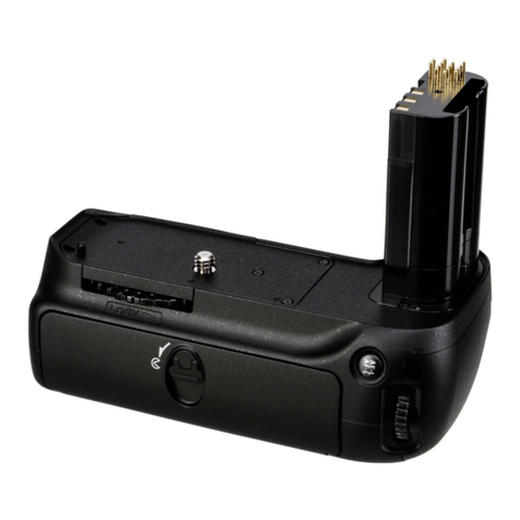
Nikon Nikonos Speedlight SB-103 User manual

Nikon
"
NIKONOB
Speedlight
INSTRUCTION
MANUAL

NOMENCLATURE
_______
_
CD
Joint collar Flash head
no<i
ti
nrlinn
® !';np,
prllir
.h
t
O-rings and lubricant @
Bracket slot o
00
Cord fastening hanger
@ Bracket screw
socket
@ Bracket Arm knob
Exposure calculation chart
scale Distance scale for underwater photography
" and
"MF
ULL" indexes
Distance scale for on-land photog
2

CONTENTS
______
--'----
__
NOMENCLATURE
. . . .. . .. . . .. .. . . .. . . . .. . . . .. . . 2
FOREWORD
.....
...
..
..
. . . .
...
.
...
....
..
.....
. 4
PREPARATION
.
...
.
..
.
....
..
. .
......
...
....
.
4-6
Examining
and
lubri
ca
ti
ng
the O-rings .
..
.
..
5
The
O-rings
and
their sealing
method
.......
6
BASIC
OPERATIONS
.
.....
....
..
...
.....
...
7-13
CONTROLS
IN
DETAIL
...
. . .
....
.
..
........
14-23
Bracket
...
...
..
....
.
...
. .
..
..
...
. . . .
..
. . . .
14
Arm
..
.......
.
........
. . .
.....
.
...........
14
Joint .
.'
....
. . .
..
. . .
...
...
.....
...
..
..
.
14-15
Synchro Socket ..
........
...
..
.
...
. . .
.....
15
Synchronization Speed
....
.
..
....
.
..
.
..
. . .
16
Shooting
Mode
Selector/Power Switch .
16-17
Exposure Calculation Chart
........
.
..
....
17
TTL
Automatic
Flash
Control
...
.
..
..
..
.
17-18
Manual
Flash
Control
..
..
.. .. ..
. . .
........
19
Exposure Compensation
.............
.
....
20
Ready-Light .
....
..
......
..
...
....
...
20-21
Cord Fastening Hanger ....
..
.
..
.
...
.
..
...
22
Wide-Flash
Adapter
SW
-
103
...
.....
.....
..
22
Multiple
Flash
Photography..
..
...
.
...
22-23
Daylight
Fill
-
In
Flash
Photography .
.......
. .23
TIPS
ON
SPEEDLIGHT
PHOTOGRAPHY
..
......
...
24
OPTIMUM
BATTERY
PERFORMANCE
...
...
..
. . .. 24
TIPS
ON
SPEEDLIGHT
CARE
..
.....
. . . .
..
......
. .
25
ACCESSORIES
.
..
........
...
. .
....
...
......
. . .26
Extension Arm
..
...
.
..
. . .. .
.....
.....
..
...
26
Double
Flash
Bracket
..
.
...
. .
...
..
......
. . .26
Double Sync Cord
...
....
...
.
........
..
...
26
O-rings
and
Lubricant
..
..
.
.....
..
...
..
...
26
SPECIFICATIONS
.
..
..
...
. .
...
. . . ..
.. ..
........
27
3

FOREWORD
________
_
The Nikonos 8peedlight 88-103,
an
amphibious high-
performance electronic flash unit with a silicon-con-
trolled rectifier and series circuitry,
is
designed for use
with the Nikonos-V, Nikonos
IV-A,
and Nikonos III. The
88-103 can be submerged to a depth of
50
meters
(160 feet) and withstand pressure of
up
to 6kg/cm2
(85Ib/in2
),
enabling it to be used
in
environments where
regular speedlights could not be taken.
In
combination with the Nikonos-
V,
the
88
-
103
features
automaticthrough-the-Iens (TTL)flash exposure control.
This means the silicon photodiode (8PD)
in
the Nikonos-
V's shutter box reads the light passing through the lens
and then automatically signals the speedlight to turn
itself off when the exposure
is
correct. 8ecause TTL
flash offers a wide range of useable apertures and
shooting distances,depth of field
is
easy to control and
shooting
as
close
as
0.
3m
(1
ft)
is
possible. Daylight
fill-in flash photography becomes easier when using the
Nikonos-V.
To
enable
itto
be used with the Nikonos
IV-A
and Nikonos
III
,the 88-103 features manual control with three power
settings: "MFULL," "M1/4," and
"M1/16."
This speedlight has the same area of coverage
as
a 28mm lens. When the Wide-Flash Adapter 8W-103
(provided) is used, the area of coverage increases to
that of a 15mm lens.
For multiple flash photography, a double flash bracket
and a double sync cord are available
as
options.
In
addition, a variety of other optional accessories
is
avail-
able to increase the versatility of the 88-103.
Even
though thisspeedlight
is
extremelyeasyto operate,
you
should still familiarize yourself with the preparatory
steps and basic operations explained
in
the first two
sections of this manual. For more detailed information,
refer to "CONTROL8
IN
DETAIL
"
and
"TIP8
ON
8PEED-
LIGHT PHOTOGRAPHY." A few minutes wisely invested
now will
payoff
later
in
years of rewarding photographic
experiences.
PREPARATION
________
_
STOP!
READ
THIS
NOTICE
BEFORE
USING
YOUR
SB·103.
THE
O·RING
SEALS
MUST
BE
EXAMINED
AND
LUBRICATED
BEFORE
USE
TO
AVOID
DAMAGING
THE
SPEEDLIGHT.
This Nikonos 8peedlight 88-103 uses O-rings to seal
and waterproof the junctions between parts.
Your
Nikonos 8peedlight 88-103 should not be considered
waterproof until you have examined the O-rings (one
each for the battery chamber cap @, the sync cord's ®
camera and speedlight plugs, and the synchro socket
cover® ).They must be
in
perfect,undamaged condition
and
properly lubricated prior to each use.
Read
the
following instructions thoroughly to familiarize yourself
with the maintenance of the O-rings.
8ecause the outer surface of your Nikonos 8peedlight
88-103has been specially treated to make
it
waterproof,
it
mustbe protected from impact. If
it
becomes damaged,
send it to a qualified technician for service before the
next use.
Your
Nikonos 8peedlight 88-103
is
watertight only when
in
perfectly serviced condition, when all O-ring seals
are
in
perfect condition, and when all components are
properly assembled and closed.
Pay
special attention to the instructions for installing
the O-rings because they are what make the Nikonos
8peedlight 88-103watertight. For the O-rings to perform
properly,they must be
in
perfect condition (with no cuts,
tears, or other imperfections) and properly lubricated.
If they are not, they will not perform properly and may
allow water to enter your flash unit.
To
prevent the
4
accidental use of a defective O-ring, always discard
old O-rings.
The
channels into which the O-rings fit must
be
free of
any foreign matterand
in
their original, smoothlyfinished
condition. If they are not, the O-rings will not seat prop-
erly and may allow water to enter your flash unit. If any
channel
in
your Nikonos 8peedlight 88-103 becomes
damaged, send the unit to a qualified technician for
service before the next use.
All
of the O-rings
in
your Nikonos 8peedlight 88-103
must be examined at the end of each dive day
and
, if
possible,after each dive.

PREPARATION-confinued
______
_
Examining and lubricating the O·rings:
1.
To
remove the O-rings, except the one
in
the synchro
socket cover, grasp the
ring
between your thumb and
forefinger. Pinch your fingers together
as
you
slide
them
in
the direction of the arrow to create slack
in
the O-ring.
Then
grasp the slack portion with your
other hand and pull the ring off (see
Fig.
1).
To
remove the O-ring
in
the synchro socket cover,
use
the edge of a credit card or dive card or some
thin, blunt, instrument. Never use a knife or other
sharp·edged object.
Push
up
on
the center of the
cover with a fingertip (or
pOinted
object), insert the
card under the ring,
and
pull it
up
to lift the O-ring out
(see
Fig
.
2).
Do
not scratch the O-ring
in
the process.
2. Visually examine each O-ring for imperfections. If
any
O-ring
is
damaged (by tears, cuts, or other imper-
fections), discard
it
immediately. If any O-ring has dirt,
sand, hair, or foreign matter
on
it
, rinse the O-ring
in
fresh water to remove
it.
3.
When
lubricating the various parts of your flash unit,
use
only the special non·water·soluble silicone
lubricant supplied with the speedlight. Never use
other lubricants (such
as
Vaseline) which are water-
soluble.
4.
To
lubricate the O-rings, smear a small amount of the
special silicone lubricant
on
your fingertips and then
gently
run
each O-ring between your fingertips. Never
use
a brush or similar object to apply the lubricant;
small hairs may fall into the channel and allow water
to enter the flash unit. While lubricating each O-ring,
examine
it
with your fingertips for imperfections. If
an
O-ring
is
properly lubricated it will glisten and wi
ll
Fig. 1
not have "gobs" of lubricant
on
it.
To
ensure the
longest possible flash unit life, apply lubricant when-
ever necessary.Lubrication protectsthe O-rings from
excessive wear; it also makes it easier to attach or
remove other parts.
5. Visually examine the channels into which the O-rings
fit to determine that each
is
clean and smooth. If any
channel
is
dirty, clean it with a non-lint-bearing mate-
rial. Coat each channel with a thin film of lubricant
while being careful not to apply too much.
6. Reseat all of the O-rings with your fingertips by
in
-
serting one side of the ring into the channel and
holding
it
in
position while rolling the other side of the
ring
into place (see
Fig
.
3)
.
To
insert the O-ring into
the channel of the synchro socket cover, push
up
on
the center of the cover with a fingertip (or pointed
object), place the
ring
over the channel, then press
it
down into place. Check that the O-ring
is
not twisted
and
that each of its edges
is
properly seated (see
Fig
.
4).
7. Check the surfaces which are opposite the O-rings
to determine that each
is
clean, smooth, and free of
foreign matter. Clean and lubricate the surfaces
in
the same manner
as
the channels.
8. When reattaching the parts with O-rings, be sure that
each O-ring seats properly and securely.
All
of the
O-rings must be properly aligned and not "pinched."

PREPARATION-continued
__
-----'--
___
_
The
preceding instructions must
be
performed
on
each
O-ring prior to each dive day and, if possible, prior to
each dive. By following these procedures
and
all other
procedures
in
this instruction manual, you will be able
to enjoy using your Nikonos.8peedlight 8B-103 for many
years.
Reminder:
An
extra set of O-rings and a tube of lubri-
cant are supplied with the flash unit. Additional O-rings
and
lubricant are available from authorized Nikon
dealers and service centers.
The
O-rings
and
their sealing
method
The
method used by the O-rings to seal and waterproof
the flash unit
is
shown
in
the following illustrations.
When a low level of pressure exists (for instance, just
underthe water'ssurface),each O-ring seals its channel
by its own elastic force (see Chart
A).
When the pressure
increases (at greater depths), the O-ring's shape
is
altered and its sealing ability
is
increased to withstand
the greater pressure.
The
pressure changes the
ring
from its original
"0"
shape (when looking at a cross-
sectional view) to a
"D
" shape (see Chart
B).
Pressure
i
Jr-
Chart A Chart B
oSlight compression
6
0°"'"
300
D-ring lubricant

BASIC
OPERATIONS
;:::::::::::::::::::;:::::=====;---;;;;;::::=====;;;:;
1 Remove the battery
• chamber
cap
@.
Turn
the battery chamber cap coun-
terclockwise and pull
it
off the
speedlight case.
Note:
The
small numbers
in
circles identify
parts
of
the
speedlight as listed
in
the
NOMENCLATURE section.
o Do
not
:Insert the batteries improperly, leave
the batteries installed when the flash unit
will not be used for an extended period,
or
leave the shooting mode selector/power
switch ® turned on except when using the
flash unit. Any
of
these may damage the
speedlight
or
cause the batteries
to
explode.
oAlways use only one brand
or
type
of
battery
at the same time.
When
replacing batteries,
replace all four at the same time.
o
The
use
of
NiCd batteries is recommended
because
of
their short recycling time; the
use
of
manganese batteries is not recom-
mendedbecause they do nothave sufficient
power
to
operate the S8-103 at full capacity.
o For more information, see "OPTIMUM
BATTERY PERFORMANCE" on page
24
.
2 Remove the AA-type
• batterycartridge @
from thebatterychamber.
Turn
the speedlight upside down
so
the battery cartridge slides out of
the battery chamber.
o
lf
the battery cartridge does not slide out
when the speedlight
is
upside down, shake
the speedlight until it does.
4
Replace
the battery
• cartridge
in
thebattery
chamber
.
Be
sure the speedlight shooting
mode selector/power switch
is
at
the "OFF" position, then align the
positioning groove @
on
the battery
cartridge with the notch
on
the
inside of the battery chamber and
slide the battery cartridge into the
chamber.
3 Install the'batteries.
• Install four 1.5V AA-type alka-
line-maganese or four 1.2V re-
chargeable
NiCd
batteries, making
sure the positive and negative
(+
and
-)
terminals are installed
as
shown
in
the diagrams
on
the car-
tridge.
7

BASIC
OPERATIONS-continued
-;:::::==:::;=
~
==
:::::::;
6
Loosen
the
joint
-knob
®l
.
To
loosen thejoint knob,turn it coun-
terclockwise while holding the jOint
plate
@.
9.
Lock
the
joint.
-Align the flash head positioning
index @ with the "normal" position
mark
on
the flash head positioning
scale,then turn the joint knob clock-
wise until the joint
is
locked
in
posi-
ti
on
.
•
See
page
15
for info
rm
at
io
n about removing
the joint.
8
1
Properly
position
the
-
joint
plate.
Turn
the joint knob so the flat sides
of the
jOint
plate are parallel with
the flat edges of the joint.
10
Loosen
the
joint
-Iever @.
Turn
the joint lever counterclock-
wise as far
as
it
will go to loosen it.
8
Insert
the
joint
plate
-
Into
the
joint
collar
CD
.
While holding the base of the joint
knob against the joint,slide the joint
plate into the joint collar until it
is
fully seated. '
• W
he
n inserting the joint plate into the joint
collar,be sure the
fla
tedges
of
thejoint plate
remain parallel to the flat edges
of
the joint.
11
Insert
the
arm
@
into
-
the
joint.
Insert the arm positioning screw
@J
into the slot
in
the joint.The arm can
be
inserted from either side of the
joint. The normal position
is
shown
in
the photo.

12
Position
the arm.
•
Al
i
gn
the arm positioning
screw with the arm
pOp
itioning
index ®
on
the joint
by
turning the
arm 90°
15
Attach
the
bracket
• @
to
the arm.
.
Slide
the open end of the bracket
between the arm knob and the grip,
seat the two bracket positioning
pins
in
the two indentations
on
the
bracket, and turn the arm knob
clockwise
as
far
as
it
will go to lock
the bracket into position.
•
Th
e correct
ar
m/bracket position
is
with the
th
r
ee
was
hers on
the
un
derside
of
the
bracket and the rubber side
of
the bracket
facing u
p.
13
Lock
the arm.
• After aligning the arm pos
i-
tioning screw with the arm posi-
tioning inde
x,
turn the joint lever
clockwise
as
far
as
it
will
go
to lock
the arm into position.
14
Loosen
the arm
•
knob
@.
Turn
the arm knob counterclock-
wise
as
far
as
it will go to loosen it
(the two bracket positioning pi
ns
on
the bottom of the grip ® will
be
visible).
16 Attach the cord
•fastening hanger
@
to
the bracket.
As
shown
in
the photo, slide the cord
fastening hanger onto the bracket.
9

BASIC
OPERATIONS-confinued
___
_
17.
Remove
the
• camera's
flash
sync
socket
cover.
Turn
the camera's sync socket
cover counterclockwise with a coin
to
remove
it.
10
18
Attach
the
camera
• body
to
the
bracket.
With the camera against the rubber
side of the bracketand the camera's
tripod socket over the bracket
screw,screwthe bracket screw into
the camera's tripod socket until the
camera and bracket are securely
attached.
Nikonos·V or Nikonos IV·A
20
Remove
the
synchro
•socket cover ®.
Turn
the synchro socketcover coun·
terclockwise,then pull
it
up.
19 Connect
the
sync
•cord ®
to
the
camera.
Remove
the dust·proof plastic cap
from the sync cord's camera plug
(silver locking ring).
In
sert the
camera plug
in
the camera's flash
socket after aligning the white index
on
the flash synchro socket with the
red
dot
on
the camera plug.
When
the camera plug is
in
serted, turn
its locking ring clockwise as far as
it
will go to secure the plug.
• Do not apply excessive force to t
he
sync
cord
's
cameraplug
an
d,
as much as possible,
avoid twisting the
cor
d.
21
Connect
the
sync
• cord
to
the
58-103
.
Remove
the dust·proof plastic cap
from the sync cord'sspeedlight plug
(black locking ring). Insert the
speedlight plug into the synchro
socket after aligning the synchro
socket index @ with the
red
index
on
the speedlight plug. When the
speedlight plug
is
inserted, turn its
locking ring clockwise
as
far
as
it
will go to secure the plug.
• To keep t
he
sync cord out
of
the way while
shooting, attach
it
to t
he
hook
of
the cord
fastening hanger.

ASA
/
ISO
24 Select an
fI
stop
from
•
the
exposure
calculation chart 0 .
Select
an
aperture from the range
of apertures that can be used at the
existing flash-to-subject distance.
22
Confirm
the
position
•
of
the
flash
head.
Confirm that the arm positioning
screw
is
aligned with the arm posi-
tioning index, the flash head posi-
tioning index
is
aligned with the
"normal" position mark
on
the flash
head positioning scale, and the flash
head
is
facing
in
the same direction
as
the camera's lens. If the arm
positioning screw
is
not properly
aligned, loosen the joint lever to
reposition
it.
If the flash head posi-
tioning index
is
not properly aligned,
loosen the joint knob to reposition
it.
o
See
page
15
for informati
on
about positioning
the flash head for close-up shooting within
approximately 1m (3.3ft).
23
Set
the
shutter
speed
•
on
the camera.
When using the Nikonos-V, set the
shutter speed/mode selector dial
to
"A"
or any shutter speed setting
from 1/1000 to 1/125sec
.;
when
using the Nikonos
IV-A,
set the
shutter speed dial to
"A
";
when
using the Nikonos III, set the shutter
speed dial to 1/60sec.
When using either the Nikonos-V
or Nikonos
IV-A
, the proper syn-
chronization speed (1/90sec.) will
be
automatically set when the
S8-103's shooting mode selectorl
power switch
is
turned
on
.
ASA/ISO
TTL flash operation with the
Nikonos·V: For example, when
shooting a subject underwater
at
1.2m (4.3ft) without the wide-flash
adapter while using ASAIISO
100
film, the useable aperture range
is
from f/2.Bto fiB.
Manual flash operation with
th
e
Niko
rl
os
·V, IV·A,
or
III: For exam-
ple, when shooting asubject
on
land
at
1.2m (4.3tt) without the wide-
flash adapter while using ASAIISO
100
film, the appropriate f/stop
at
"MFULL"
is
f/16, at "M1/4"
is
fiB,
and
at
"M1/16"
is
f/4.
o
The
exposure calculation chart is adhesive-
backed, enabling
it
to be attached to the
speedlight case.
11

BASIC
OPERATIONS-confinued
_
__
_
25 Setthe fI
stop
on
-the
lens.
For TTL flash operation, select the
best aperture from the exposure
calculation chart
by
considering
the desir
ed
amount of depth of field
and
recycling time. For manual
flash operation, select the best
aperture from among those corre-
sponding to the "MFULL," "M1/4,"
and
"M1/16" settings
by
consid-
ering the desired amount of depth
of field.
In
the photograph,f/4
is
s
et.
27,
Wait
for
the ready-
-
light
@
to
light.
As
soon
as
the flash ready-light
lights, the SB-103
is
ready to fire.
Except for Nikonos
III
,
if
the camera
you
are using
has
a viewfinder
ready-light,
it
will light when the
SB
-
10
3 is completely recycled.
Note that with the Nikonos-V and
Nikonos
IV-A
, the exposure meter
must
be
turned
on
to activate the
viewfinder ready-light.
12
26
Set
the
shooting
-modeselectorI
power
switch
CW
.
For TTL flash operation, set the
shooting mode selector/power
switch to "
TTL.
" For manual flash
operation, set it to "MFULL
,"
"M1/4
,"
or "M
1/16
."
Because this switch doubles
as
apower switch,the SB-103
is
turned
on
whenever the switch
is
set to
other than "OFF."
o
With
a set of fully recharged NiCd
ba
tteries,
the ready·light will light in approximately
6 seconds; wi
th
a fresh set of alkaline-
manganese batte
ries,
it will light in approx-
imately 9 seconds.
ol
feit
her the S8-
103
's or the camera
's
ready-
light does not light
or
blink, check that: the
batteries are properly installed, the camera
and flash unit are securely connected; and
the shutter speed/shooting mode and ASAI
I
SO
film speed setting on the camera are
correctfy set.
o
See
page
21
for
in
fo
rm
ationabout ready-light
exposure
wa
rn
ing
in
fo
rm
ation.
o
TTL
automatic flash operation
is
' possible
only with the Nikonos·V
oAs soon as
yo
u tu
rn
on the 58·
103
when '
using the Nikonos-V, the shutter speed LED
in
dicator inside the viewfinder will blink if
the shutter speed/mode selector
dia
l is set
at "A" or at any
sh
utter speed from 1/
1000
to
1/30sec. If the selector dial is set at
"
MOO
"
or
"8," no
sh
utter speed indicator
will blink or light. As soon as
yo
u tu
rn
on
t
he
58·
10
3 when using t
he
Nikonos I
VA
the
red
vie
wf
in
der
LED
tu
rns
off.
o For
in
formation about the
va
rious shooting
modes,seepages 16to
17.
28
Take
the
picture.
-
When
the shutter
is
released,
the speedlight fires. After a few
seconds,the ready-lights inside
the
camera's viewfinder and
on
the
speedlight will light againto indicate
the flash unit
is
fully recycled
and
ready for the
ne
xt shot.

o
lf
the flash unit fires at its maximum output
during
TTL
flash operation, its ready·light
will blink for approximately 2 secon
ds
after
the shutter
is
released
to
warn that the shot
may have been underexposed. In th
is
case,
recheck the shooting distance/apertu
re
combination selected or move closer to the
subject,
if
necessary.
This
warning is also
indicated by the viewfinder ready·light
of
the
Nikonos·V.
29
TUrn
off the
flash
unit.
•
To
conserve battery power
between shooting sessions,turn the
shooting mode selector/power
switch
on
the speedlight to "OFF."
o Turning the shooting mode selector/power
switch
off
between sessions will also help
prevent batteryleakage.
13

CONTROLS
IN
DETAIL
_____
_
Nikonos III
Nikonos-V or Nikonos IV-A
Bracket
@
As
indicated
in
the diagram, there are two positions for
the bracket screw
@:
one for the Nikonos-V and Nikonos
IV-A
and another for the Nikonos III.
To
reposition the
bracket screw, unscrew
it
, then screw
it
back into the
hole or the threaded end of the bracket slot @ . Once
screwed into the bracket slot,the bracket screw can
be
moved to any position.
The
larger hole
in
the center allows the sync cord to
be
connected through the bracket to the Nikonos III.
The small hole
on
the underside of the bracket
is
the
tripod socket ®. The small hole that goes completely
through the bracket
is
not used with the Nikonos 8B-103.
the arm knob and the grip, seat the two bracket posi-
tioning pins
in
the two indentations
on
the bracket, and
turn the arm knob clockwise
as
far
as
it
will go to lock
the bracket into position. The correct arm/bracket
position
is
with the three washers on the underside of
the bracket and the rubber side ofthe bracket facing
up
.
14
Arm
@
To
attach the arm to the
jOint
@, insert the arm posi- .
tioning screw@ into the slot
in
the joint from either side.
Al
ign the arm positioning screwwith the arm positioning
index ® on the joint by turning the arm 90°. After align-
ing the arm positioning screw with the arm positioning
index,turn the joint lever @ clockwise
as
far as
it
will go
to lock the arm into position. When the arm
is
attached
in
this manner, the speedlight's axis will always intersect
with the lens's optical axis, even if the flash head
is
moved
up
or down on the arm. (Normally, the joint
is
locked at the top of the arm.) Before diving,
be
sure the
.
jOint
knob @ and joint lever are locked tightly.
To
attach the arm to the bracket, turn the arm knob @
counterclockwise as far as it will go to loosen it (the two
bracket positioning pins
on
the bottom of the grip ®will
be visible).
81ide
the open end of the bracket between
Joint
®
The
joint connects the arm to the speedlight and allows
the flash head to
be
positioned as required for various
shooting situations.
The arm can
be
inserted from either side of the
jOint
,
but to use it
in
the normal position, insert
it
as
shown
in
the photo. When using two 8B-103 8peedlights (or
an
8B-
103
and
an
8B-102) and the optional Double
Flash
Bracket, insert the arm that
is
next to the camera's film
advance lever into the joint from the direction opposite
that shown
in
the photo. (Flash head positioning scales
are provided on both sides ofthe joint.)
The
joint lever allows the flash head to
be
turned
on
the
arm's axis and moved
up
or down the arm
as
required.
The joint knob
is
used to adjust the angle of the flash
head (the angle of intersection between the speedlight's
a
xi
s and the lens's optical axis).The normal angle of the
flash head
is
with the flash head positioning index @ at

the "normal" positioning mark @
on
the flash head
po
sitioning scale.
The
"normal" position
is
used for
shooting between 1m
(3
.3ft) and infinity. For close-up
shooting within approximately 1m
(3
.3ft), loosen the
jOint
knob
, point the flash head toward the subject,then
tighten
the
joint knob.
In
addition to the "normal" posi-
tion mark
on
the flash head positioning scale, "
O.6m
(2ft)
"@
and
"O
.3m
(1
ft)" @positionmarksareprovided
for
use
when shooting subjects at these distances.
However, when the flash head
is
not
in
the "normal"
positi
on
,the joint must
be
attached to the top of the arm
or
the
flash head will not
be
pointed
at
the subject.
To
detach the joint from the speedlight, turn the joint
knob
counterclockwise and slide the joint plate out of
the joint collar while pulling the joint knob.
cord or when washing the speedlight with the speedlight
plug
removed from the synchro socket, attach the
synchro socket cover to protect the socket.
To
attach
the
socket cover,press
it
against the socket to seat the
O-r
i
ng
, then turn its locking ring clockwise
as
far
as
.
it
will
go
.
• To simplify identification, both the tip of the sync
co
rd's speedlight plug
andthe inside
of
the synchro
socket
are color
·code
d yellow.
Synchro
Socket
@
To
connect the sync cord ® to the speedlight, remove
the synchro socket cover ®
by
turning
it
counterclock-
wise and pulling
it
up. Remove the dust-proof plastic
cap from the sync cord's speedlight plug ® (black
locking ring). Insert the speedlight plug into the synchro
socket after aligning the synchro socket index ® with
the
red
index
on
the speedlight plug. When the speed-
light plug
is
inserted, turn its locking
ring
clockwise
as
far
as
it
will
go
to secure the plug.
Never submerge the speedlight
in
water with the
synchro socket cover removed or get the sync cord
plugs wet. Always make sure the sync cord plugs are
securely attached before entering the water.
After shooting underwater, wipe off any water droplets
with a soft cloth before removing the plug to prevent
water from entering the socket. When not using the sync
15

CONTROLS
IN
DETAIL-continued
___
_
Camera I Sync Speed I
Nikonos·
V·
1/90 sec. or slower
Nikonos IV·A" 1/90 sec. or slower
Nikonos
III
1/60 sec. or slower
Synchronization
Speed
The
shutter speed at which the S8-103 synchronizes
with a camera depends upon the camera being used.
The
table shows the flash sync speeds of various
cameras.
80th the Nikonos-V and Nikonos
IV-A
cameras auto-
matically switch to the proper synchronization speed
when the S8-
103
's
shooting mode selector/power
switch
is
set to "TTL," "MFULL," "M1/4," or "M1/16
";
when
it
is
set to "OFF," the automatic switchover func-
tion
is
canceled.
oAperture-priority exposure mode
("
A
")
operation
on
the Nikonos-V
and Nikonos
IV-A
is canceled
wh
en
th
e S8·103 is turned on. To deter-
mine the correctaperture, use the S8·103's exposure calculation chart
(see page
17
).
Camera
Setting
I Operable
Shutter
Speed I
Viewfinder
Information
A 1/90 sec.
1/1000 to 1
/125
sec. 1/90 sec. Correct shutter s
pe
ed b
li
nks"
1/60 to 1/30 sec.
as
se
t
M90 or B as set -
A 1/90 sec.
LED
do
es not
li
g
ht
M (1/90 sec.) or B as set -
-as set -
I Remarks
TTL
operable
TTL
inopera
bl
e
• When battefles
In
the Nlkonos-
Vor
Nlkonos
IV-A
are exhausted, reset the Nlkonos-V's shutter speed/mode selector dIal to M90 (1/90 sec.) or B
(Bulb),
or
the Nikonos IV-A's shutter speed dial to M
(1190
sec.) or B (B
Ulb).
TTL
automatic flash contr
ol
is not possible when the Nikonos-V
is
in the M
90
or
B modes.
••
This
indicates the
correct
shutter speed as determined
by
the subject's brightness and the aperture setting. Although this is not a speedlight
function, it is helpful when using daylight fill-in flash shooting.
Shooting
Mode Selector/Power
Switch
®
The
shooting mode selector/power switch
has
five c!ick-
stop settings.
The
shoot
ing
modes that can
be
used with
specific cameras are listed above.
"OFF"
position
The
speedlight
is
turned off when the switch
is
set at
this position.
"TTL"
position-TTL
(through·the·lens) Automatic
Flash Mode
This mode, which can
be
used only
in
conjunction with
the Nikonos-V camera, automatically controls the flash
exposure Through·The·Lens (TTL).
In
this mode, the
Nikonos-V's
SPD
(silicon photodiode) reads the light
passing through the lens and automatically signals the
S8-
103
to turn itself off when the exposure
is
correct.
16
The
range of useable apertures
is
larger (from f/2.8 to
f/22 when using ASAIISO
100
film) with
TTL
flash,
and
you
can easily control the depth of field.
In
addition, the
TTL
mode makes daylight fill-
in
flash
and
close-
up
photography easier than ever.
o
The
useable film speed range for
TTL
operation is from ASA/ISO 25
to
400
. Forinformation about the apertures that can be used
at
v
ar
ious
film speed
s,
see page
18
.
o
TTL
operation is not
po
ssible with the Nikonos IV·A or III
or
when the
Nikonos-V
's
shutter speed/mode selectordial is s
et
at
M90
(t
/90sec.)
or B(BulbY.
o Even
if
the Nikonos-V
's
shutter speed/mode selector dial is set at "A"
or
from 1/30 to 1/
I000
sec"
TTL
operation
is
not po
ss
ible when: the
s
yn
c cord is not securely connected, the ASA/
ISO
film is set beyond
ASA/ISO 400,
or
the batteries are completelyexhausted,
ol
n
TTL
automatic flash operation, the
SB
-
103
emits amounts
of
light
sufficient for subjects having average reflectivity,
Th
erefore, corre
ct
ex
po
sure maynotbe obtainable
if
the subject
's
reflectivity isextremely
low or hi
gh.

"MFULL," "M1/4,"
and
"M1/16"-Manual
Flash
Modes
These modes can
be
used with the Nikonos-V, Nikonos
IV-A
,and Nikonos III. Manual control
is
very convenient
when the correct exposure cannot
be
obtained through
TTL
automatic operation.The SB-103 has three manual
control modes for selection according to the flash-to-
subject distance and the shooting situation. The guide
numbers are
GN
20
(10) at the "MFULL" position,
GN
10
(5) at "M1/4," and
GN
5
(2
.5) at "M1/16" when using
ASAIISO
100
film. (The guide numbers
in
parentheses
are for underwater photography).
To
determine the cor-
rect aperture, use the exposure calculation chart or
perform the calculations by yourself (see page
19)
.
TTL
Automctic
Flcsh
Control
In
TTL automatic flash photography, the useable aper-
tures are from f/2.8 to f/22 (when using ASAIISO
100
film), although the actual range for a specific shooting
situation depends upon the flash-to-subject distance,
the ASAIISO film speed, the type of photography (on-
land or underwater), and whether or not the wide-flash
adapter
is
being used.
The
actual ranges for specific situations can be easily
determined with the exposure calculation chart.
Exposure
\,,;CIICLIlCTlon
In
flash photography, which apertures can
be
used
is
closely related to the flash-to-subject distance.
To
de-
termine the useable apertures, use the exposure calcu-
lation chart.
Example
1:
When shooting
on
land at f/4 without the wide-flash
adapter while using ASA/ISO
100
film, you can take
pictures of subjects located between 0.
9m
(3ft) and
5m
(16.4ft).
In
the same manner, when shooting underwater at
f/11
with the wide-flash adapter while using ASAIISO 400
film,you can shoot subjects located between 0
.3
m
(1
ft)
and 1.
2m
(4
.3ft).
Before you select
an
aperture, always take the flash-to-
subject distance into consideration.
To
increase the
flash-to-subject coupling distance as much as possible,
select a larger flstop (a numerically smaller f-number).
In
the opposite case, close-up shooting, select a smaller
flstop (a numerically larger f-number).
17

CONTROLS
IN
DETAIL
-
continued
====:;:;:
::;:;------::----:-
Example
2:
When
shooting underwater at 2.5m (8.2ft) without the
wide-flash adapter while using ASA/ISO
50
film,
you
must use f/2.
8.
When several flstops are useable
at
a specific flash·to-
subject distance, make your selection by taking the
desired depth of field
and
speedlight recycling time into
consideration.
When using
an
ASAIISO film speed not shown
in
the
exposure calculation chart (for example, ASAIISO 64),
calculate the difference between the film speed
in
use
and
the closest film speed
in
the chart to determine
the appropriate intermediate aperture setting to
use.
For example, when shooting underwater at 0.3m
(1
ft)
with the wide-flash adapter while using ASA/ISO
64
film,
determine the closest film speed (ASA/ISO 50)
and
its
useable aperture range (f/2.8 to f/11). Since
64
is
ap-
proximately one-third larger than
50,
the correct inter-
mediate aperture settings will be one-third larger than
those shown
in
the chart for ASA/ISO
50
film. For
in-
stance, if the correct aperture when using ASAIISO
50
ASA/ISO
Example
3:
When shooting
on
land
at
1.2m (4.3ft) without the wide-
flash adapter while using ASAIISO
100
film and
you
want the largest depth of field possible, select f/16.
If
you
want to minimize recycling time
as
much
as
possible,
select f/2.8.
Even
though the exposure calculation chart may appear
to indicate otherwise, the minimum flash-to-subject
coupling distance for underwater photography
is
0.3m
(1
ft).
film
is
f/2.8, the correct aperture when using ASA/ISO
64
film
is
f/2.8 plus one-third (one third closer to f/4).
Likewise, if the aperture shown
in
the chart
is
f/11, the
correct aperture
is
f/11
plus one-third (one third closer
to
f/16).
In
the TTL automatic mode, the S8-103's useable ASAI
ISO
film speed range
is
from ASA/ISO
25
to
400,
its
useable aperture range
is
from f/2.8 to f/22,
and
its
flash-to-subject coupling distance range
is
from 0.3m
(1ft) to
14
m (46ft).
•
These
figures should only
be
used
as
a
guide
because
flash·
to·subject coupling distance
ranges
are affectedby
the
existing conditions
(water
quality,
surroundings, subjects, andso
on).
18

Man
Manual flash operation allows you to control the light
output of the SB-103 by setting the shooting mode
selector/power switch to one of three positions:
"MFULL
,"
"M1/4," or "M1/16
."
To
determine which setting to
use,
select
an
aperture
from the exposure calculation chart
and
set it
on
the
lens.
At
each intersection of a distance line ® and
an
aperture line
on
the aperture scale @,one of four condi-
tions will
be
present:
1)
the distance line will intersect
the extreme right-hand edge of the aperture line (the
"MFULL" mark),
2)
the distance line will intersect a
semicircle (the "M1/4" mark),
3)
the distance line will
intersect a triangle (the "M1/16" mark), or 4) the dis-
tance line will intersect
an
unmarked portion of the f/stop
line.
The
first three conditions indicate the manual flash
mode that can
be
used
at
those particular f/stops.
Example
2:
If the shooting distance changed to 3m
(9
.Bft) but
you
.still wanted to use "MFULL," you would
have
to use
an
intermediate aperture setting between f/S.6 and fiB.
To
determine the correct f/stop without using the expo-
sure calculation chart, divide the
GN
from the chart
by the flash-to-subject distance (in meters).
Example 3: .
When
shooting
on
land
at
Sm
(16.4ft) without using the
wide-flash adapter while using ASA/ISO
100
film and
"MFULL":
The
GN
for
"MFULL"
at
ASA/ISO
100
on
land
is
20
from the chart. Divide the
GN
of 20 by the
flash-to-subject distance of
Sm
to get the correct aper-
ture, f/4. Because water absorbs a great deal of light,
however,
you
cannot use the same
GN
underwater
as
on-land or your shot will be underexposed.
Instead, multiply the on-land
GN
by 1/2 to 1/3 for under-
When shooting underwater at 1.2m
(4
.3ft)without using
the wide-flash adapter while using ASA/ISO 400 film,
you can select one of three aperture/mode settings:
f/16 at "MFULL
,"
fiB at "M1/4," or f/4
at
"M1/16
."
water photography. (The underwater GNs shown are
1/2 of the corresponding on-land GNs.)
Guide Numbers
in
the Manual Mode
•
The
values
in
parentheses are when the Wide·Flash Adapter
SW-I03
is
being used.
•
The
full amount
of
light
is
emitted when the shooting mode selector
is
at "M
FU
LL."
19

CONTROLS
IN
DETAIL-continued
___
_
Exposure Compensati
on
When using TTL automatic flash control with the
Nikonos-V camera, you can use its ASAIISO film speed
dial to make
an
exposure compensation for the shooting
situation orto create intentionallyover- or underexposed
photos.
The
relationship between the exposure compensation
value and ASA/ISO film speed dial setting
is
shown
in
the following chart:
The
useable aperture range
and
flash-to
-s
ubject cou-
pling distance range for TTL automatic flash photogra-
phy changes according to the exposure compensation
value being used. When making
an
exposure com-
pensation,use the aperture/shooting distance combina-
tions
in
the reset ASAIISO film speed column
in
the
exposure calculation chart. For example, when making
Ready-Light
@
After its power switch
is
turned
on,
the ready-light
on
the S8-103 will light to indicate that the speedlight has
recycled and
is
ready to fire. If you are using either
a Nikonos-V or Nikonos
IV-A
camera, its viewfinder
ready-light will also light at the same time to let
you
know the speedlight
is
ready for the next shot.
In
addition, the viewfinder ready-lights of the Nikonos-V
and Nikonos
IV-A
blink to warn of improper settings. If
this happens, check that: the camera
and
flash unit are
securely connected,
and
the shutter speed/shooting
mode and ASAIISO
fi
lm speed
on
the camera are cor-
rectly set.
20
a
+2
exposure compensati
on
while using ASAIISO
100
film, use the aperture/shooting distance combinations
in
the ASAIISO
25
column
in
the exposure calculation
chart.
o
Po
sitive
(+)
exposure compensation cannot be made when using ASAI
I
SO
25 film, andnegative
(-)
exposure compensation cannot be made
when using ASA/ISO 400 film.
In
these cases, make
the
necessary
compensation
by
using one
of
the manual flash modes. Note that the
Nikonos-V's viewfinder ready·light blinks
if
you attempt to make a
-2
or greater exposure compensation while using
ASA
/
ISO
200 film, or
a
-lor
greater exposure compensation while using ASAIISO 400 film
in
the
TTL
mode.
o When you finish making the exposure compensation,
be
sure to reset
the
ASA
/ISO film speed dial
on
the Nikonos·V to its original setting.
. o
lf
you photograph a subject with very high
reflectivity-such
as a
mirror or metallic
surface-in
the
TTL
mode, underexposure is almost
certain to
occur
.
To
prevent this, use manualcontrol.
o
The
ready·light goes out when the flash
unit
is turned off.
o
When
the exposure meter
of
the Nikonos
-V
or
Nikonos
JV.A
is not
activated, the camera's viewfinder ready-light will not light even
if
the
speedlight is turned
on
(except when the shutterspeed/mode selector
dial
or
shutter speed dial is set
at
MOO
or
M). Always confirm that the
viewfinder ready-light is lighted before shooting.
o
When
the shutterspeed/mode selectordial
or
shutterspeed dial
of
the
Nikonos·
Vor
Nikonos
JV.A
is set
at
MOO
or
M, the viewfinder ready-
light lights when the flash unit ready-light lights.
o
As
the voltage
of
the batteries decreases with use, the GN
of
the flash
unit decreases slightly.
o
The
voltage
of
NiCd batteries decreases rapidly when their power is
almost exhausted, increasing the recycling time.
When
this occurs,
stop using them immediately and recharge them or they may be
damaged.
o
When
using alkaline-manganese batteries,
if
recycling takes 30
seconds
or
longer, replace the batteries with a fresh set.
oAspecial red
LED
is built into one end
of
the
firing tube to ensure stable
light output. If
you
release the camera's shutterbefore
the
S8-
103
is
fully
recycled,
the
LED might light
up-this
is not a malfunction.
Other manuals for Nikonos Speedlight SB-103
1
Table of contents
Other Nikon Batteries Pack manuals
Popular Batteries Pack manuals by other brands

Tripp Lite
Tripp Lite BP480V40C Specification sheet

PowerWalker
PowerWalker BP A72T-12x9Ah user manual

PowerWalker
PowerWalker BP I2 120T-40 9Ah Series installation instructions

DualLite
DualLite UFO-3AW installation instructions

Tripp Lite
Tripp Lite BP36V14-2U owner's manual

Anker
Anker SOLIX Solarbank E1600 user manual