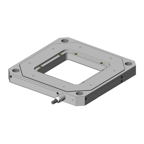
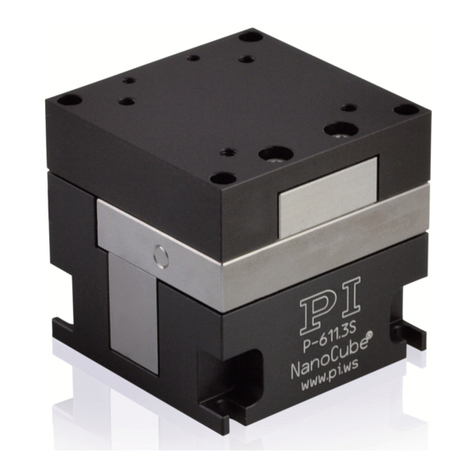
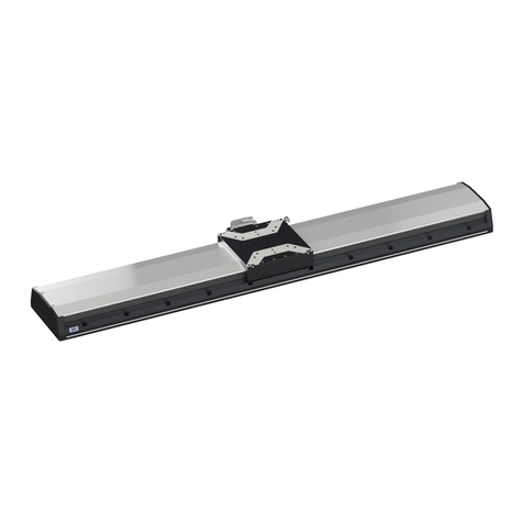
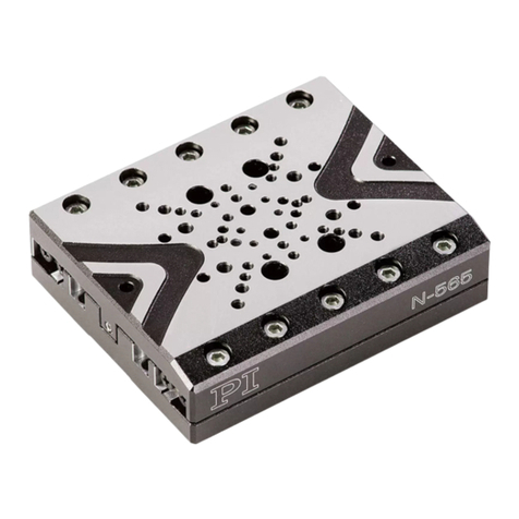
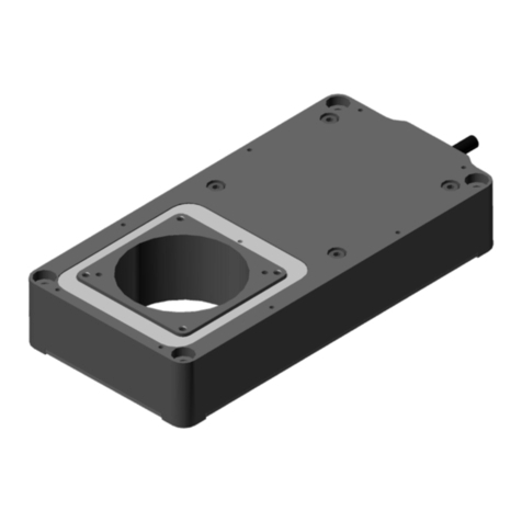
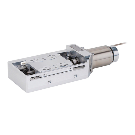
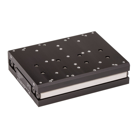
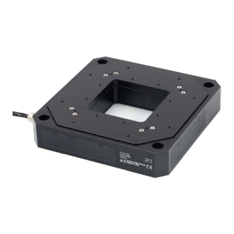
PI L-306 Series User manual

User Manual
L306T0002, applies to L-306.011100 / 011112 / 013112
MMa, 2019-AUG-20
PI miCos GmbH, Freiburger Strasse 30, 79427 Eschbach, Germany
Phone +49 7634 5057
-0, Fax +49 7634 5057-99, Email info@pimicos.ws, www.pi.ws
L-306.011100 / 011112 / 013112
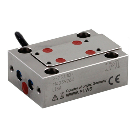
Compact Z positioner
Figure 1: Schematic product view

User Manual
L306T0002, applies to L-306.011100 / 011112 / 013112
MMa, 2019-AUG-20
PI miCos GmbH, Freiburger Strasse 30, 79427 Eschbach, Germany Page 2 / 25
Phone
+49 7634 5057-0, Fax +49 7634 5057-99, Email info@pimicos.ws, www.pi.ws
Contents
Other Applicable Documents 3
Safety 4
Intended Use................................................................................................................................................. 4
General Safety Instructions........................................................................................................................... 4
Organizational Measures .............................................................................................................................. 4
Product Description 5
Product View and Component Designations ................................................................................................ 5
Direction of Motion....................................................................................................................................... 5
Technical Features ........................................................................................................................................ 6
Position Sensors .............................................................................................................................................. 6
Limit Switches.................................................................................................................................................. 6
Reference Point Switch ...................................................................................................................................6
Unpacking / Scope of Delivery 6
Mechanical Installation 7
General Notes on Installation ....................................................................................................................... 7
Attaching the Positioner to a Surface ........................................................................................................... 8
Connecting the Positioner to the Protective Earth Conductor................................................................... 10
Affixing the Load to the Positioner ............................................................................................................. 12
Connecting the Positioner to a Controller 13
Starting and Operating the Positioner 14
Maintenance 15
General Notes on Maintenance.................................................................................................................. 15
Performing a Maintenance Run.................................................................................................................. 15
Lubrication .................................................................................................................................................. 15
Manually Moving the Platform ................................................................................................................... 16
Cleaning the L-306 ...................................................................................................................................... 17
Customer Service ........................................................................................................................................ 17
Disposal 18

User Manual
L306T0002, applies to L-306.011100 / 011112 / 013112
MMa, 2019-AUG-20
PI miCos GmbH, Freiburger Strasse 30, 79427 Eschbach, Germany Page 3 / 25
Phone
+49 7634 5057-0, Fax +49 7634 5057-99, Email info@pimicos.ws, www.pi.ws
Specifications 19
Technical Data............................................................................................................................................. 19
Maximum Ratings ....................................................................................................................................... 20
Ambient Conditions and Classifications...................................................................................................... 21
Dimensions.................................................................................................................................................. 22
Pin Assignment HD D-Sub 26 (Male)........................................................................................................... 24
Legal Information 25
CE Compliance............................................................................................................................................. 25
Figures, Commitment, Actuality ................................................................................................................. 25
Copyright..................................................................................................................................................... 25
Contact Person, Feedback........................................................................................................................... 25
Other Applicable Documents
Product Document
L-xxx positioners Short Instructions MP146EK
C-863.12* User Manual MS249
C-663.12* User Manual MS241
Technical Note C663T0005
C-885* User Manual C885T0002
C663.12C885* User Manual C663T0004
C863.20C885* User Manual C863T0005
SMC Hydra* Technical Manual SMC Hydra (SMC-Hydra CM
TT.doc)
* Depending on the ordered controller. Further documents included in the data carrier(s)
provided with the controller.
Further devices and software tools from PI that are mentioned in this documentation are, if
applicable, described in separate manuals.
You can download current versions of user documentation and data sheets for standard
products from our web site www.pi.ws.

User Manual
L306T0002, applies to L-306.011100 / 011112 / 013112
MMa, 2019-AUG-20
PI miCos GmbH, Freiburger Strasse 30, 79427 Eschbach, Germany Page 4 / 25
Phone
+49 7634 5057-0, Fax +49 7634 5057-99, Email info@pimicos.ws, www.pi.ws
Safety
Intended Use
The product is a laboratory device as defined by DIN EN 61010. It is intended for indoor use and
use in an environment which is free of dirt, oil, and lubricants.
In accordance with its design, the product is intended for single-axis positioning, adjusting and
shifting of loads at different velocities. The product is not intended for applications in areas, in
which a failure would present severe risks to human beings or the environment.
The product is intended for horizontal mounting.
The intended use of the product is only possible when completely mounted and connected.
The product must be operated with a suitable controller. The controller is not included in the
scope of delivery of the positioner.
General Safety Instructions
The product is built according to state-of-the-art technology and recognized safety standards.
Improper use of the product may result in personal injury and/or damage to the positioner.
Only use the product for its intended purpose, and only if it is in perfect condition.
Read the user manual.
Immediately eliminate any faults and malfunctions that are likely to affect safety.
The operator is responsible for correct installation and operation of the positioner.
Organizational Measures
User manual
Always keep this user manual available when using the positioner.
The latest versions of the user manuals are available on our website www.pi.ws for
download.
Add all information from the manufacturer such as supplements or technical notes to
the user manual.
If you give the product to other users, also include this user manual as well as all other
relevant information provided by the manufacturer.
Only use the device on the basis of the complete user manual. Missing information due
to an incomplete user manual can result in minor injury and damage to equipment.
Only install and operate the product after you have read and understood this user
manual.
Personnel qualification
The product may only be installed, started up, operated, maintained, and cleaned by authorized
and appropriately qualified personnel.

User Manual
L306T0002, applies to L-306.011100 / 011112 / 013112
MMa, 2019-AUG-20
PI miCos GmbH, Freiburger Strasse 30, 79427 Eschbach, Germany Page 5 / 25
Phone
+49 7634 5057-0, Fax +49 7634 5057-99, Email info@pimicos.ws, www.pi.ws
Product Description
Product View and Component Designations
Figure 1: Parts of the positioner (schematic view)
1Platform incl. mounting interface for payload
2Base body
3ESD warning sign
4Product label, incl. detailed model designation and serial no.
5Connector (HD D-Sub 26, male, protection cap removed)
6Protective earth (PE) connector
7Mounting hole for surface mounting
8Product line label
Direction of Motion
Figure 2: Direction of motion of the platform
Z (arrow direction:) Direction of motion on positive command

User Manual
L306T0002, applies to L-306.011100 / 011112 / 013112
MMa, 2019-AUG-20
PI miCos GmbH, Freiburger Strasse 30, 79427 Eschbach, Germany Page 6 / 25
Phone
+49 7634 5057-0, Fax +49 7634 5057-99, Email info@pimicos.ws, www.pi.ws
Technical Features
All types of this product line are Z positioners with crossed roller bearings including an anti-
creep system.
Position Sensors
Models L-306.011112 and L-306.013112 include a linear incremental encoder. For
specifications, see the “Technical Data” section (p. 19).
Limit Switches
The product provides optical limit switches.
Each limit switch closes a contact on a dedicated line to the controller. If reached, the controller
stops the motion. If the controller does not stop the motion in time, the positioner runs into a
hard stop.
Reference Point Switch
The positioner is equipped with one direction-sensing reference point switch that is located at
about the midpoint of the travel range. This sensor provides a TTL signal indicating whether the
positioner is on the positive or negative side of the reference point switch.
The commands that use the reference signal are described in the user manual for the controller
and/or in the corresponding software manuals.
Unpacking / Scope of Delivery
1. Before opening the packaging, check the packaging for signs of damage. If there is any
sign of damage, contact PI immediately (sevice@pi.de).
2. Compare the delivered items with the items listed in the contract and the list below.
Component
L-306-type precision Z positioner, model according to the order
Adapter/extension cable for the ordered controller (length: 3 m)
Mounting accessory, incl.
-4 screws ISO 4762 M6x20
-2 alignment pins ISO 8734 4m6x12
Short instructions for positioners with electric motors
Packaging material
3. Remove the positioner from the packaging. Keep the packaging material for potential
subsequent transport, storage or return of the positioner.

User Manual
L306T0002, applies to L-306.011100 / 011112 / 013112
MMa, 2019-AUG-20
PI miCos GmbH, Freiburger Strasse 30, 79427 Eschbach, Germany Page 7 / 25
Phone
+49 7634 5057-0, Fax +49 7634 5057-99, Email info@pimicos.ws, www.pi.ws
Mechanical Installation
General Notes on Installation
NOTICE
Electrostatic hazard
Touching the pins in the connections of the positioner can damage electrostatic sensitive
devices (ESD) of the positioner. Also for this reason, the positioner is supplied with a
protection cap on the connector.
Do not remove the protection cap from the connector until you connect the positioner
to the controller.
NOTICE
Cable break!
A cable break leads to failure of the positioner.
Install the positioner so that the cable is not bent too strongly or crushed.
NOTICE
Heating of the positioner during operation!
The heat produced during operation of the positioner can affect your application.
Install the positioners that the application is not impaired by the dissipated heat.
Avoid excess of the allowed max. velocity (5 mm/s). Operation within the allowed
velocity range is automatically ensured by correct selection/detection of the product
model in the motion control software.
INFORMATION
For optimal repeatability, all components must be connected firmly together.
INFORMATION
The use of locating pins during mounting reduces deviations from the ideal alignment of the
positioner.
If possible, simulate the positioner motion with a mounted load or make suitable
calculations to detect collisions or unfavorable center of gravity constellations.
If necessary, take suitable constructive measures to avoid collisions and instability in
the overall system.

User Manual
L306T0002, applies to L-306.011100 / 011112 / 013112
MMa, 2019-AUG-20
PI miCos GmbH, Freiburger Strasse 30, 79427 Eschbach, Germany Page 8 / 25
Phone
+49 7634 5057-0, Fax +49 7634 5057-99, Email info@pimicos.ws, www.pi.ws
Avoid or mark danger zones that result from the installation of the positioner and the
application, in accordance with the legal regulations.
Attaching the Positioner to a Surface
INFORMATION
For mounting onto a surface, the positioner provides 4 mounting holes matching M6 screws in
its base body and 2 holes Ø 4 mm for alignment pins in the bottom side.
Mounting screws and locating pins are provided with the positioner.
Figure 3: Hole positions and hole pattern (bottom view)
1Hole for mounting screw (1 of 4 total)
2Hole for alignment pin (1 of 2 total)

User Manual
L306T0002, applies to L-306.011100 / 011112 / 013112
MMa, 2019-AUG-20
PI miCos GmbH, Freiburger Strasse 30, 79427 Eschbach, Germany Page 9 / 25
Phone
+49 7634 5057-0, Fax +49 7634 5057-99, Email info@pimicos.ws, www.pi.ws
Requirements
You have read and understood the general notes on installation (p. 7).
You have provided a suitable surface (for the required position and depth of the holes
for accommodating the screws and locating pins, see illustration above).
−Four M6 threaded holes are present.
−If you use locating pins to align the positioner: Two Ø 4 mm locating holes are
present.
−The flatness of the surface is ≤10 µm.
−For applications with large temperature changes: The surface should have the same
or similar thermal expansion properties as the positioner (e.g., surface made of
aluminum).
You have accounted for the space required to route cables without bending and
according to regulations.
Tools and accessories
Mounting accessories; in the scope of delivery.
−4 socket head screws, ISO 4762 M6x20
−2 dowel pins, ISO 8734 - 4 m6 × 12, for use as locating pins
Hex key AF 5 (not included in the scope of delivery)
Mounting the positioner onto a surface
1. If you use locating pins to align the positioner:
a. Insert the locating pins into the respective holes in the surface.
b. Place the positioner on the surface so that the locating pins are inserted into the
corresponding locating holes on the other side.
2. Otherwise: Align the positioner on the surface so that the corresponding mounting
holes in the positioner and the surface overlap.
3. Insert the screws into all mounting holes and tighten.
4. Check that the positioner is affixed firmly to the surface.

User Manual
L306T0002, applies to L-306.011100 / 011112 / 013112
MMa, 2019-AUG-20
PI miCos GmbH, Freiburger Strasse 30, 79427 Eschbach, Germany Page 10 / 25
Phone
+49 7634 5057-0, Fax +49 7634 5057-99, Email info@pimicos.ws, www.pi.ws
Connecting the Positioner to the Protective Earth Conductor
INFORMATION
It is only necessary to connect the positioner to the protective earth conductor when both of
the following conditions are met:
The load on the platform of the positioner must be connected to the protective earth
conductor, but it is not possible to connect the protective earth conductor directly to the
load.
The load and the platform are connected conductively to each other.
INFORMATION
Observe the applicable standards for connecting the protective earth conductor.
An M4 hole for the protective earth conductor connection is marked on the corresponding side
of the positioner.
Figure 4: Components / mounting of the protective earth connector
1
Base body of the positioner
2Flat washer
3Safety washer
4Screw
5Cable lug
6Protective earth conductor
Requirements
You have read and understood the general notes on installation (p. 7).

User Manual
L306T0002, applies to L-306.011100 / 011112 / 013112
MMa, 2019-AUG-20
PI miCos GmbH, Freiburger Strasse 30, 79427 Eschbach, Germany Page 11 / 25
Phone
+49 7634 5057-0, Fax +49 7634 5057-99, Email info@pimicos.ws, www.pi.ws
Tools and accessories
Suitable protective earth conductor: Cross-sectional area of the cable core ≥ 0.75 mm2
Philipps head screwdriver or compliant tool
Connecting the positioner to the protective earth conductor
1. If necessary, attach a suitable cable lug to the protective earth conductor.
2. Loosen the screw and remove the mounted components of the PE connection (see
illustration above).
3. Affix the cable lug of the protective earth conductor on the protective earth connection
using the M4 screw and further components, according to the sequence shown in the
profile view above.
4. Tighten the M4 screw with a torque of 1.2 Nm to 1.5 Nm.
5. Make sure that the contact resistance at all connection points relevant for attaching the
protective earth conductor is <0.1 Ω at 25 A.

User Manual
L306T0002, applies to L-306.011100 / 011112 / 013112
MMa, 2019-AUG-20
PI miCos GmbH, Freiburger Strasse 30, 79427 Eschbach, Germany Page 12 / 25
Phone
+49 7634 5057-0, Fax +49 7634 5057-99, Email info@pimicos.ws, www.pi.ws
Affixing the Load to the Positioner
NOTICE
Impermissibly high load on the positioner!
An impermissible high load impairs the motion of the platform and can damage the
positioner.
When considering the mass and mounting method of the load, pay attention to the
specified maximum permissible forces that may act on the platform (p. 19).
NOTICE
Excessively long screws!
Screws and locating pins that are inserted too deeply can damage the positioner.
Pay attention to the depth of the mounting holes in the platform.
Only use screws and locating pins of the suiting length for the respective mounting
holes.
Figure 5: Position of the holes for mounting the payload
Requirements
You have read and understood the general notes on installation (p. 7).
You have mounted the positioner properly onto a surface.
The positioner is not connected to the controller.
You have prepared the load so that it can be affixed to the mounting holes on the
platform:
−The distance between the center of gravity of the load and the center of the
platform is as small as possible in all directions.
−At least two points are provided for mounting the load on the platform (ideally:
three or four mounting points).
−If you use locating pins for aligning the load: You have made two locating holes of
Ø 4 mm H7 in the load for accommodating locating pins.

User Manual
L306T0002, applies to L-306.011100 / 011112 / 013112
MMa, 2019-AUG-20
PI miCos GmbH, Freiburger Strasse 30, 79427 Eschbach, Germany Page 13 / 25
Phone
+49 7634 5057-0, Fax +49 7634 5057-99, Email info@pimicos.ws, www.pi.ws
Tools and accessories
At least 2 screws of suitable length. Options:
−M4 screws
−M6 screws
Suitable tool for tightening the screws
Optional: 2 dowel pins, ISO 8734 - 4 m6 of suitable length for aligning the load on the
positioner.
Affixing the load
1. Align the load so that the selected mounting holes in the platform can be used to affix
it.
2. If you use locating pins to align the load:
a. Insert the locating pins into the locating holes in the platform.
b. Place the load on the platform so that the locating pins are inserted into the
corresponding locating holes on the other side.
3. Use the screws to affix the load on the selected mounting holes in the platform.
4. Check that the load is affixed firmly to the platform of the positioner.
Connecting the Positioner to a Controller
NOTICE
Damage if an incorrect controller or cable is applied!
Connecting a positioner to an unsuitable controller or using an unsuitable motor
cable can cause damage to the positioner or controller.
Only connect the positioner to a suitable controller (see “Data Table”, p.19)
If an adapter cable is applied: Use the cable included in the delivery.
Requirements
You have read and understood the general notes on installation (p.7).
You have installed the controller.
You have read and understood the user manual of the controller.
The controller is switched off.
Connecting the positioner to a controller
1. Remove the protection cap from the connector.
2. Connect the positioner to the controller (if applicable, using the adapter cable for your
controller included in the delivery).
3. Use the integrated screws to secure the connections against accidental disconnection.

User Manual
L306T0002, applies to L-306.011100 / 011112 / 013112
MMa, 2019-AUG-20
PI miCos GmbH, Freiburger Strasse 30, 79427 Eschbach, Germany Page 14 / 25
Phone
+49 7634 5057-0, Fax +49 7634 5057-99, Email info@pimicos.ws, www.pi.ws
Starting and Operating the Positioner
Requirements
You have read and understood the user manual for the controller used.
You have read and understood the manual for the PC software used.
The controller and the required PC software have been installed. All connections on the
controller have been set up (see "Connecting the Positioner to a Controller" (p.13) and
the user manual for the controller).
Starting and operating the positioner
1. Start and operate the controller (see user manual for the controller).
Configure the controller during startup using the PC software for the positioner used
(see user manual for the controller and the PC software): Select the entry in the
positioner database that exactly matches the positioner model used.
2. Start a few motion cycles for testing purposes (see user manual for the controller).

User Manual
L306T0002, applies to L-306.011100 / 011112 / 013112
MMa, 2019-AUG-20
PI miCos GmbH, Freiburger Strasse 30, 79427 Eschbach, Germany Page 15 / 25
Phone
+49 7634 5057-0, Fax +49 7634 5057-99, Email info@pimicos.ws, www.pi.ws
Maintenance
General Notes on Maintenance
NOTICE
Damage due to improper maintenance!
Improper maintenance can result in misalignment and failure of the L-306.
Only loosen screws according to the instructions in this manual.
Performing a Maintenance Run
Depending on the operating conditions and the period of use of the L-306, the following
maintenance measures are required:
Maintenance run
The maintenance run serves to distribute the existing lubricant.
After 500 operating hours or at least after 1 year, perform a maintenance run over the
entire travel range, in order for the existing lubricant to be distributed evenly.
If you operate your positioner continuously over only a short travel range (<20%of the
entire travel range), perform a run across the entire travel range approximately every
2000 motion cycles.
Lubrication
Under laboratory conditions, the positioner needs extra lubrication in exceptional cases only.
For continuous industrial use, the lubrication intervals must be defined individually.
Do not relubricate the L-306 without consulting our customer service department.
(p. 17).

User Manual
L306T0002, applies to L-306.011100 / 011112 / 013112
MMa, 2019-AUG-20
PI miCos GmbH, Freiburger Strasse 30, 79427 Eschbach, Germany Page 16 / 25
Phone
+49 7634 5057-0, Fax +49 7634 5057-99, Email info@pimicos.ws, www.pi.ws
Manually Moving the Platform
INFORMATION
It is necessary to repeat the reference move after moving manually and connecting to the
controller.
In some cases it may be helpful or necessary to move the platform by hand. E.g. this can be
necessary when the platform is stuck at the beginning or the end of the travel range (has
reached the hard stop).
Requirements
The positioner is not connected to the controller.
Tools and accessories
Hex key AF 1.5 mm or compliant tool
Procedure
1. Insert the hex key in the corresponding hole of the platform shown below.
2. If lifting of the platform is required: Turn the hex key clockwise until the inteded
platform position is reaced.
For moving down, turn the hex key counter-clockwise correspondingly.the nsert the hex
key in the corresponding hole of the platform shown below.

User Manual
L306T0002, applies to L-306.011100 / 011112 / 013112
MMa, 2019-AUG-20
PI miCos GmbH, Freiburger Strasse 30, 79427 Eschbach, Germany Page 17 / 25
Phone
+49 7634 5057-0, Fax +49 7634 5057-99, Email info@pimicos.ws, www.pi.ws
Cleaning the L-306
Requirements
You have disconnected the positioner from the controller.
Cleaning the positioner
If necessary, clean the surface of the positioner with a cloth that has been dampened
with isopropyl alcohol or a mild cleanser/disinfectant.
Customer Service
For inquiries and orders, contact your PI sales engineer or send us an email (service@pi.de).
If you have questions concerning your system, have the following information ready:
−Product and serial numbers of all products in the system
−Firmware version of the controller (if present)
−Version of the driver or the software (if present)
−Operating system on the PC (if present)
If possible: Take photographs or make videos of your system that can be sent to our
customer service department if requested.

User Manual
L306T0002, applies to L-306.011100 / 011112 / 013112
MMa, 2019-AUG-20
PI miCos GmbH, Freiburger Strasse 30, 79427 Eschbach, Germany Page 18 / 25
Phone
+49 7634 5057-0, Fax +49 7634 5057-99, Email info@pimicos.ws, www.pi.ws
Disposal
In accordance with EU law, electrical and electronic equipment may not be disposed of in EU
member states via the municipal residual waste.
Dispose of your old equipment according to international, national, and local rules and
regulations.
In order to fulfil the responsibility as the product manufacturer, PI undertakes environmentally
correct disposal of all old PI equipment made available on the market after 13 August 2005
without charge.
Any old PI equipment can be sent free of charge to the following address:
Physik Instrumente (PI) GmbH & Co. KG
Auf der Roemerstrasse 1
76228 Karlsruhe, Germany

User Manual
L306T0002, applies to L-306.011100 / 011112 / 013112
MMa, 2019-AUG-20
PI miCos GmbH, Freiburger Strasse 30, 79427 Eschbach, Germany Page 19 / 25
Phone
+49 7634 5057-0, Fax +49 7634 5057-99, Email info@pimicos.ws, www.pi.ws
Specifications
Technical Data
L-306.011100 L-306.011112 L-306.013112 Unit Tolerance
Motion and positioning
Travel range 13 mm
Sensor resolution - 5 50 nm
Design resolution 2.5 0.005 0.05 nm
Minimum incremental motion 0.5 0.1 0.1 µm typ.
Unidirectional repeatability 0.2 0.1 0.1 µm typ.
Bidirectional repeatability ±2 ±0.5 ±0.5 µm typ.
Pitch ±175 µrad typ.
Yaw ±150 µrad typ.
Straightness / flatness ±3 µm typ.
Velocity 5 mm/s max.
Reference and limit switches Optical
Mechanical properties
Guide type Crossed roller guide, anti-creep system
Drive screw type Ball screw
Drive screw pitch 0.5 mm
Push / pull force 20 N max.
Holding force, power off 20 N typ.
Permissible lateral force 10 N max.
Load capacity 20 N max.
Permissible torque in θX, θY1 Nm max.
Permissible torque in θZ2 Nm max.
Drive properties
Motor type 2-phase stepper motor DC motor
Operating voltage 48 V max.
Power consumption 5 7 W max.

User Manual
L306T0002, applies to L-306.011100 / 011112 / 013112
MMa, 2019-AUG-20
PI miCos GmbH, Freiburger Strasse 30, 79427 Eschbach, Germany Page 20 / 25
Phone
+49 7634 5057-0, Fax +49 7634 5057-99, Email info@pimicos.ws, www.pi.ws
L-306.011100 L-306.011112 L-306.013112 Unit Tolerance
Miscellaneous
Operating temperature range 5 … 40 °C
Humidity 20% … 80% rel., not condensing
Material Anodized aluminum, steel
Mass 0.6 kg ±5 %
Moved mass 0.25 kg ±5 %
Connection HD D-Sub 26 (male)
Cable length (mounted cable) 0.5 m
Recommended controllers C-663.12
SMC Hydra
C-885 with C-663.12C885
ACS modular controller
C-863
C-884
C-885 with
C-863.20C885
ACS modular
controller
Maximum Ratings
Model Maximum operating
voltage
Operating frequency Maximum power
consumption
L-306.011100 48 V 0 Hz 5 W
L-306.011112 48 V 0 Hz 5 W
L-306.013112 48 V 0 Hz 7 W
This manual suits for next models
3
Table of contents
Other PI Valve Positioner manuals
Popular Valve Positioner manuals by other brands

Samson
Samson 3731-5 Mounting and operating instructions

Micronix
Micronix PPS-28 series Reference manual

Siemens
Siemens SIPART PS2 6DR5xx0 series Compact operating instructions

Badger Meter
Badger Meter RCV SRI990 quick start guide

GEM
GEM 1434 mPos Installation, operating and maintenance instructions

Burkert
Burkert SideControl BASIC quick start